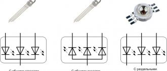
Diagnostic methods
The simplest method, which is most often used by radio amateurs, is to check light-emitting diodes with a multimeter for performance using probes. The method is convenient for all types of light-emitting diodes, regardless of their design and number of pins. By setting the switch to the “continuity check, open circuit check” position, touch the leads with the probes and observe the readings. By connecting the red probe to the anode and the black probe to the cathode, the working LED should light up. When changing the polarity of the probes, the number 1 should remain on the tester screen.
To accurately test multi-color LEDs with multiple leads, you need to know their pinout. Otherwise, you will have to randomly sort through the terminals in search of a common anode or cathode. Don't be afraid to test high-power LEDs with a metal substrate. The multimeter is not capable of disabling them by measuring in dial mode.
Testing an LED with a multimeter can be done without probes, using sockets for testing transistors. Typically, these are eight holes located at the bottom of the device: four on the left for PNP transistors and four on the right for NPN transistors. The PNP transistor is opened by applying a positive potential to the emitter “E”. Therefore, the anode must be inserted into the socket labeled “E”, and the cathode into the socket labeled “C”. A working LED should light up. To test in the holes for NPN transistors, you need to change the polarity: anode - “C”, cathode - “E”. This method is convenient for checking LEDs with long and solder-free contacts.
It does not matter in what position the tester switch is located. Checking the infrared LED is the same, but has its own nuances due to invisible radiation
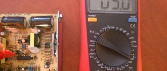
At the moment the probes touch the terminals of the working IR LED (anode - plus, cathode - minus), a number of about 1000 units should appear on the device screen. When changing polarity, there should be a unit on the screen.
To check the IR diode in the transistor testing sockets, you will additionally have to use a digital camera (smartphone, telephone, etc.). The infrared diode is inserted into the corresponding holes of the multimeter and the camera is pointed at it from above. If it is in good condition, then IR radiation will be displayed on the gadget’s screen in the form of a glowing blurry spot.
Testing high-power SMD LEDs and LED matrices for functionality requires, in addition to a multimeter, a current driver. The multimeter is connected in series to the electrical circuit for several minutes and the change in current in the load is monitored. If the LED is of poor quality (or partially faulty), then the current will gradually increase, increasing the temperature of the crystal. The tester is then connected in parallel with the load and the forward voltage drop is measured. By comparing the measured and passport data from the current-voltage characteristics, we can conclude that the LED is suitable for use.
In modern lighting technology, light-emitting diodes (LED) are often used. As you know, they are much more reliable than ordinary light bulbs, but they can still sometimes fail. In order to check the LED's performance, several methods are used. Let's take a closer look at each of them.
Test sequence
To operate the LED, a low voltage constant current is required. To obtain it, various devices are used, which are miniature power supplies that are elements of the design of lighting devices.
It is not always possible to carry out verification by actually connecting to such blocks. In this case, you need to use a multimeter.
Considering the features of the device, you can easily understand how to check the LED with a multimeter. Since it has a semiconductor junction in its structure, then, by analogy with a conventional diode, it must pass current in a certain direction. If the current is sufficient, the LED will emit light.
To check the LED with a multimeter, you need to switch the device to the diode ringing mode, then:
- the red (positive) probe of the multimeter is connected to the anode, that is, the positive electrode;
- the black (negative) probe of the multimeter is connected to the cathode - negative electrode;
- the display will show the voltage drop across the pn junction;
- If you change the polarity of the multimeter connection, there should be no voltage drop (no current flows). In this case, the LED can be considered serviceable.
Similarly, you can check an LED with a simple tester, which is an open circuit consisting of a piece of conductor, a DC source and a test lamp.
A situation is possible when, in the process of checking a powerful lighting LED in the manner described above, the voltage is reflected on the display, the element lights up, but when connected to the circuit, the brightness is not strong enough. This is determined by the naked eye without any measurements. In this case, most likely there is a crystal defect. This LED needs to be replaced.
Currently, special devices - LED TESTER - are being produced and sold. Each such device is an LED tester, made in the form of a device with a built-in power supply and a set of connectors for testing devices of various types.
Features of diodes
A standard diode is a component of the electrical network and acts as a pn junction semiconductor. Its structure allows current to pass through the circuit in only one direction - from the anode to the cathode (different ends of the part). To do this, you need to apply “+” to the anode and “-” to the cathode. Due to this feature of the product, if you suspect a breakdown, it can be checked with a tester or multimeter.
Various types of diodes.
Today in radio electronics there are several types of diodes: Types of diodes:
- Light-emitting diode. When an electric current passes through such an element, it begins to glow as a result of the transformation of energy into a visible glow;
- protective or regular diode. Such elements in the electrical network act as a suppressor or voltage limiter. One of the varieties of this element is the Schottky diode. It is also called a Schottky barrier diode. Such an element, when connected directly, gives a low voltage drop. In Schottky, instead of a pn junction, a metal-semiconductor junction is used.
It will be interesting Ways to check transistors for performance
Here is a small selection made up of specific diodes and their corresponding Vf values, which were obtained when testing them with a multimeter. All diodes were previously checked for serviceability.
If ordinary parts and LEDs are used in the vast majority of electrical appliances, then Schottky ones are used mainly in high-quality power supplies (for example, for devices such as computers). It is worth noting that testing a conventional diode and a Schottky diode is practically no different, since it is carried out according to the same principle. Therefore, there is no need to worry about this issue, because the operating principle of both Schottky and conventional diodes is identical.
Schottky diode
Being a component of an electronic circuit, such semiconductor elements often fail. The most common reasons for their failure are:
- exceeding the maximum permissible direct current level;
- excess reverse voltage;
- poor quality part;
- violation of the device operating rules established by the manufacturer.
Moreover, regardless of the cause of loss of performance, failure can be directly caused by either a “breakdown” or a short circuit. In any case, if there is an assumption that the electrical network has failed in the semiconductor area, it is necessary to diagnose it using a special device - a multimeter. Only to carry out such manipulations you need to know how to check the diode using it correctly.
What is a multimeter
A multimeter is a universal device that performs a number of functions:
- measures voltage;
- determines resistance;
- checks wires for breaks.
It will be interesting How to make a power regulator on a triac with your own hands
Using this device you can even determine the suitability of the battery.
Checking the LEDs in the lamp.
How to test a diode
After we have figured out the semiconductors of the electrical circuit and the purpose of the device, we can answer the question “how to check the diode for serviceability?” The whole point of checking diodes with a multimeter is their one-way electrical current carrying capacity. If this rule is observed, the electrical circuit element is considered to function correctly and without failures. Conventional diodes and Schottky diodes can be easily tested using this device. To check this semiconductor element with a multimeter, you need to do the following manipulations:
- you need to make sure that your multimeter has a diode test function;
- If such a function is available, we connect the probes of the device to the side of the semiconductor from which the “ringing” will be carried out. If this function is missing, then use the switch to switch the device to 1 kOhm. You should also select the mode for measuring resistance;
- the red wire of the measuring device must be connected to the anode end, and the black wire to the cathode end;
- after this, you need to observe changes in the forward resistance of the semiconductor;
- we draw conclusions about the presence or absence of voltage
The unit can then be switched to check for leaks or high circuits. To do this, you need to change the location of the diode output. In this state, it is also necessary to evaluate the obtained values of the device.
Checking the power supply
Checking is greatly facilitated if there is a source of appropriate voltage nearby.
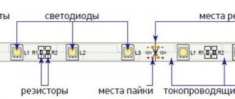
To understand whether the LED strip is working or not, it is enough to apply the required 12-24-36V to it. You don't even need to solder the wires.
Connect two conductors to the output terminals of the block, and simply touch their tips to the outer copper pads at the beginning of the tape. If the glow is uniform and not dim, then everything is fine.
But when nothing lights up, you need to look for the reason. The most important assistant in this is a multimeter.
First of all, check whether the required voltage is coming out of the power supply? Maybe it's all about him.
You need to check between contacts “+V” and “-V”.
Or “+V” and “COM”.
If the voltage is normal (+ - 10%), then look further along the chain.
If you don’t have a multimeter, you can check using indirect signs. However, you should not rely on them:
after applying 220V voltage, the green LED on the unit should light up
if you listen, any power source in working condition should emit a faint characteristic noise
When this is not the case, then we can assume that the unit is faulty. After which, you still have to look for a device to measure the output voltage and confirm your guesses.
Main conclusions
It is not difficult to check LEDs with a multimeter if you understand the principle of their operation. The main task is to prepare the conditions, modify the probes or make special contacts. The correct polarity plays an important role, changing which will not allow even a working element to glow. The process does not take much time; preparation, dismantling or disassembling of devices takes longer. The general principle is to apply the appropriate voltage to the problem element, from which it should light up if it is in working condition. If the glow is not observed even when the polarity is changed, it means that the LED (or section of the strip) is faulty and must be replaced.
Previous
Lamps and lampsHow to make a lamp from LED strip for 12 and 220 Volts with your own hands
Next
LEDsHow to check the performance of a diode with a multimeter
Modes in a multimeter for testing LEDs
This invention has electrical characteristics that include current strength and voltage drop. Using a multimeter, these indicators are checked, which indicates the performance of the LED. The maximum operating current is indicated by the manufacturer on the product packaging.
There are standards for each group of LEDs. The voltage for white, blue and green varies from 3 to 3.6 volts, and for red, orange and yellow - from 1.8 to 2.2 volts.
In addition, there is a method different from the previous one. In this case, it is necessary to use the PNP block on a multimeter, which is designed specifically for testing LEDs. This connector allows you to run the element being tested at full power, at which it is possible to see whether it is working or not.
At the initial stage, the anode is connected to the socket marked with the letter E, and the cathode must be plugged into the socket marked with the letter C. When you turn on the multimeter, this element should light up, and there is no need to set the switch to a certain value.
This method can test more powerful elements, but the inconvenience of using it is that to check the LED it must be unsoldered from the board.
To check the suitability of an LED, the polarity must be determined. You don't need to be an expert to distinguish an anode from a cathode. In an unused new LED, one leg is shorter than the other, which is shorter is the cathode, respectively, the other is the anode.
If the LED is reused, then to determine the polarity it is necessary to check the head of the element for light transmission. Where the cup is visible, it will be the cathode. Also, for convenience, manufacturers put a mark on the cathode side in the form of a mark.
Features of the tape: advantages and disadvantages
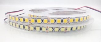
Appearance of SMD 2835 tape
LED strip 2835 is very similar in appearance to SMD 3528. But SMD 2835 has better characteristics. This applies to all products with a diode density of 60, 120 and higher, as well as with a voltage of 12 or 24V.
During the manufacture of this model, the LEDs are “pressed” to the substrate in order to reduce their heating, as well as for installation into the flexible printed circuit board strip. SMD is made on a high-quality two-layer board with a width of 10 mm, which ensures good conduction of electric current, as well as excellent heat dissipation. Some manufacturers, in order to reduce the cost of LED products of this type, often use the following two approaches:
- LEDs are strongly “clamped”;
- They put on the tape a housing from 2835 diodes with an internal chip from less powerful 3528 diodes.
In order to identify low-quality LED products, you should pay attention to the following points:
- price. The less the LED strip costs, the lower its real quality of work will be and the less it will serve you;
- thin wires;
- thin board (less than 10 mm). Low-quality products often have a width of 8 mm.
Glow of high-quality SMD 2835 tape
The luminous flux of low-quality products of this type rarely has the standard 50 Lm. Typically, real indicators are much lower and are at the level of 8-9 Lm. In this case, the power consumption will be no higher than 10 watts per meter. But this indicator depends on the density of diodes (30, 60, 120 or higher)
Note! Real power consumption is of great importance for calculating the power of the power supply for each LED strip. Here you need to take into account not only the length and voltage (12 or 24V), but also the density of LEDs (30, 60, 120 or higher)
To determine the power you need to use a tester. A high-quality LED strip SMD 2835 should have a power per meter of at least 9 watts (for a product with a diode density of 60) and 18 watts for 120. SMD 2835 has many advantages that have helped it occupy a significant niche in the lighting products market and be in great demand :
simple, easy and quick installation;
- maximum light output parameter;
- high reliability;
- low power consumption.
But we can’t talk about the advantages without touching on the disadvantages of this product. When buying SMD, remember:
- the tape must be installed on a metal plate or heat-dissipating profile;
- the need to connect a power supply, since LEDs have low voltage (12 or 24V).
As you can see, SMD 2835 has both disadvantages and advantages. But in general, it is worth noting that among the wide variety of LED products, this model has proven itself worthy.
Other verification methods
In addition to a multimeter, you can check LEDs using a battery. The best option is a CR2032 battery, which is used in the computer motherboard. Its voltage is 3 V, which is enough for most LEDs.
It is possible to use 4.5 or 9V batteries, but in such cases you will need to connect a ballast resistor, which gives a voltage drop to safe levels. For Krona you will need 750 Ohms, for 4.5V batteries - 150-200 Ohms.
The LED strip can be checked with a 12 V battery. These are found in remote controls and doorbells. By connecting the contacts of the tape to the corresponding poles of the battery, areas with burnt-out elements are determined. No less problematic elements are the connection areas of individual parts of the LED strip - connectors that oxidize and stop conducting current. Before you start dialing, you need to check their condition - perhaps the problem lies there.
https://youtube.com/watch?v=cEWDkwjRf0Y
How to ring an LED lamp
Let's look at how to check an LED light bulb with an E27 base, suitable for ordinary household lamps and chandeliers. Before you test an LED lamp with a multimeter, you will have to disassemble it. First you need to disconnect the diffuser. It is usually glued to the body, so you need to carefully insert a piece of thin plastic (plastic card, pick or other object) into the slot and, gradually moving it along the gluing line, separate the parts. If the seam is too strong and does not give in, you can warm it up with a hairdryer. Testing the open board with a multimeter is done using probes.
Alternatively, you can use a Krona battery. You need to select the desired polarity and check the status of the LEDs with short touches. You cannot maintain contact for a long time because the battery voltage is too high.
Infrared
As we acquire consumer electronic devices, each of us gradually becomes the owner of a whole battery of remote controls. As long as the equipment obediently responds to your commands, there is nothing to worry about.
But it is quite possible that desperate attempts to change the channel or turn down the brightness of the chandelier do not lead to any result. In such cases, first check the status of the infrared LED, through which the remote control transmits your requirements to the main device.
Read also: Wrought iron benches for a cemetery
There are several ways to check the IR LED in a remote control or other device. Let's start with the simplest:
If you don’t have a gadget capable of removing it, the suspected LED can be removed by replacing it with a super-bright or SMD-type LED. Just make sure that the operating voltage of both elements is the same.
If the test LED emits visible light when pressing buttons on the remote control (most likely, it will be dim), then the IR LED has already served its purpose.
A more complicated method, but it does not require a camera or soldering. You can use an infrared photodiode. When infrared radiation hits the sensor of this element, a potential difference is formed at its terminals.
If pulse curves appear on the device screen, the LED under test is in working condition. If you observe complete calm, then it’s time to buy a new IR LED.
Troubleshooting and Troubleshooting
A malfunction of the fluorescent lamp is expressed in:
- Complete lack of inclusion.
- Short-term flickering of the lamp with further switching on.
- Continuous flickering without further switching on.
- Buzzing.
- Flickers in combustion mode.
This can adversely affect a person’s vision, so you should immediately diagnose the breakdown and begin repairing the lamp. For this purpose you will need a multimeter or resistance tester.
Often the LL does not light due to poor contact between the lamp pins and the socket contacts. The holders wear out and oxidize over time. You should clean them with an alcohol-containing liquid, an eraser, fine sandpaper, and, if necessary, bend or replace the contact plates for better contact with the pins. It should be remembered that the LDS does not work at temperatures below –50 ˚С and with voltage surges of more than 7%.
Integrity of spiral electrodes
The lamp does not light up. Check with a multimeter or indicator for the presence of resistance with a mini-bulb. The switch is set to measure resistance - the minimum range, with probes touching the pins first on one side, then on the other. A faulty spiral will show zero resistance (the thread is broken). The whole thread will show a slight resistance - from 3 to 16 ohms. If even one of the spirals shows a break, the lamp must be replaced. It will not be possible to restore functionality with such a breakdown.
Faults in the electronic ballast
New generation lamps use electronic ballasts (EPG). To understand whether the ballast is working properly, replace it with one that is known to work. If the lamp turns on, it means that there was a breakdown in it. Old ballast can be repaired at home. First, you can try replacing the fuse with a similar one with the same diameter and fuse link. If the spiral filaments glow faintly, the capacitor between them is broken. It needs to be replaced with a similar one, but with an operating voltage of 2 kV. Cheap ballasts use 250–400 V capacitors, which often burn out.
Electronic ballast device
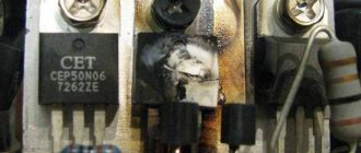
Transistors can burn out due to voltage surges. When operating a welding unit or any powerful equipment, it is advisable to turn off the LDS. Transistors can be taken from decommissioned ballasts or selected from a table. After replacing any element, you need to check the serviceability of the lamp by inserting a 40 W lamp into it.
How to check the choke of a fluorescent lamp
Signs of a throttle malfunction:
- humming of the lamp due to the rattling of the plates;
- the lamp lights up normally, then darkens around the edges and goes out;
- LDS overheating;
- after switching on, snakes run inside the flask;
- strong flicker.
Throttle check
To check the throttle for serviceability, remove the starter from the lamp and short-circuit the contacts in its socket. Take out the lamp and short-circuit the contacts in the sockets on both sides. The multimeter is set to resistance measurement mode, the probes are connected to the contacts in the lamp socket. A winding break will show infinite resistance, and an interturn short circuit will show a value (arrow) near zero.
How to check the starter
If, when turned on, the LDS flickers but does not light up, the starter is faulty. It will not be possible to ring the starter separately from the lamp with a multimeter, since without voltage its contacts are open. The test circuit for this element includes a 60 W light bulb and a starter connected in series to a 220 V network.
How to check capacitance of a capacitor with a tester
A faulty capacitor located between the power supply wires reduces the efficiency of the lamp by up to 40%. In operating condition, the efficiency is 90%, which is more economical. For LLs up to 40 W, a capacitor with a capacity of 4.5 μF is suitable. Too low a capacitance will reduce efficiency, a high capacitance will cause flickering. The serviceability of the capacitor is checked with a multimeter with the appropriate function.
Specific cases
Repairing an LED strip powered by 12 or 24 V is carried out in the most common way - by removing the problem area and connecting the working parts of the strip to each other. Sometimes another one is inserted in place of the cut section if the tape is attached to the load-bearing surface and it is too difficult to dismantle it.
However, in order to repair a tape with direct power from a 220 V network, this technique is not suitable. Such lamps have minimum sections of 0.5 or 1 m. This is done in order to collect 60 LEDs, each of which consumes approximately 3.5 V. They are connected in series, so the failure of one element means the failure of an entire meter section of the strip .
Important! It is usually not possible to cut out such a large piece; it is easier to make repairs. To do this, you will need a regular set of tools (soldering iron, scissors, etc.). It's good if the tape can be removed from the supporting structure, but you can try to repair it right on the spot.
Repairing the problematic section is possible; you just need to find the burnt-out LED and replace it. The search is carried out by alternately closing the contacts of all elements. When the burnt-out element is closed, all the others will flash brightly. All that remains is to carefully remove the defective LED and solder a normal one in its place. Care must be taken because the voltage on the LEDs is 220 V, and this is life-threatening.
Testing LEDs in dialing mode
A multimeter is a universal meter that allows you to check the serviceability of almost any electrical device or element. To check a light-emitting diode using a tester, it is necessary that the device can switch to diode testing mode, which is most often called continuity testing.
Checking the serviceability of the LED with a multimeter is carried out in the following order:
- Set the tester switch to diode test mode.
- Connect the multimeter probes to the contacts of the element being tested.
When connecting an LED, you should take into account the polarity of its terminals (the black probe of the measuring device is connected to the cathode, and the red one to the anode). However, if the exact location of the poles is unknown, then there is nothing wrong with an incorrect connection, and the LED will not fail in this case.
- The continuity current is small and is not enough for the LED to work at full capacity. Therefore, you can see the glow of the element by slightly darkening the room.
- If there is no way to dim the lighting, you need to look at the readings of the multimeter. When checking the working diode, the values on the device display will differ from one.
Visually checking the LEDs in the video:
Using this method, you can check even a powerful diode for functionality. The disadvantage of this method is that it will not be possible to diagnose the elements without removing them from the circuit. To test LEDs in a circuit, adapters must be connected to the probes.
Sometimes the serviceability of a part is checked by measuring the resistance, but this method is not widely used because to use it, you need to know the technical parameters of the diode.
Checking the diode on the board
It is often necessary to test an LED without desoldering it from the circuit. In such cases, the technique remains the same, but the technology changes. Since it is impossible to insert the LED legs into the multimeter slots, probes are used. The hole sizes of the slots for testing transistors are too small, so the probes will have to be modified. Thin contacts should be attached to the free ends, which can be used as:
- sewing needles;
- straightened paper clips;
- pieces of thin wire, etc.
Several ways to check it yourself
There are three main ways to test LEDs at home. With minimal familiarity with the branch of physics called electrical engineering, all these methods should not turn out to be something difficult and impossible to implement.
- The first and most common is checking the LEDs with a multimeter. If, of course, it is available and you know how to use it.
- You can also verify that the LED is working properly by applying voltage to it from a Krona battery or several AA batteries connected in parallel.
- The third available method is to use old mobile phone chargers as a current source to test LEDs. Here, however, as in the second case, you will have to work a little with your hands. Clean the wires by first cutting off the phone connector and touching the exposed wires to the anode and cathode. If the LED lights up, it means it is working. Don’t be afraid to confuse minus and plus – you won’t burn out the LED.
Check with multimeter No. 1
Most people rarely, if ever, use a multimeter at home. But those who are well acquainted with electricity feel like they have no hands without a tester. We won’t consider all the capabilities of this smart thing here, but it’s worth telling how to use it to determine if the LED is working properly.
Not all multimeters are the same. To perform the above task, you will need a device that has a “dialing” function, specifically designed for checking LEDs with a tester.
So: set the device to the “dialing” mode. We touch the anode with the red probe, and the cathode with the black probe. If everything is done correctly and the LED is working properly, it will light up. If there are no marks on it where the anode is and where the cathode is, nothing will happen. In this case, the probes should be swapped, and if in this case the LED does not show signs of life, it means it has burned out.
And the last secret for checking an LED with a multimeter. It is recommended to dim the general lighting, otherwise you may simply not notice that it is glowing. In any case, the indicators of the device will be different from one, if, of course, the LED is working properly.
Check with multimeter No. 2
The vast majority of modern multimeters are equipped with a PNP block, which can also be used to test the performance of LEDs. The power of the device should be sufficient to visually verify its serviceability. To do this, you only need to connect the anode into a special hole marked with the letter E, and the cathode into the hole marked with the letter C. In any mode of the multimeter, a working LED will light up.
This method is only suitable for individual LEDs, which must first be removed from the general device.
Checking LEDs without desoldering
Here you will have to slightly upgrade the multimeter probes. It is necessary to solder short pieces of steel clip to the opposite ends of the wires, having previously isolated them from each other. Insert this improvement into the corresponding holes on the PNP block, and use the probes to touch the anode and cathode of the LED being tested.
As an alternative current source, if there is no multimeter in the house, you can use the same AA batteries or “crown”. This will be even more convenient and faster, since you won’t have to upgrade the probes. On the opposite end, you can simply put on special alligator clips and simply connect them to the plus and minus on this improvised source.
Preparing for work
To repair an LED TV you will need:
- a professional soldering station that blows a thin stream of very hot air, later referred to as a hair dryer;
- flux;
- some tin for tinning the contact pads;
- depending on the chosen replacement strategy, a small amount of thin copper wire;
- scissors;
- tweezers;
- Super glue.
You will also need the main tool, a device for checking the LED lines of LED TVs. It could be a multimeter. It is convenient to operate as a tester with the ability to set the operating voltage. A laboratory transformer with thin contact probes performs well. How exactly to use these devices will be clear from the following sections.
In order not to damage the matrix elements and other complex components of the TV, it is advisable for the technician to prepare a lot of free space for himself. At least two screen sizes. This area will house a separate matrix and LED backlight unit.
Important! It is undesirable to leave fingerprints and other dirt on the lenses, reflectors, display and protective film, so you need to thoroughly wash your hands and clean the TV case. It would be a good idea to stock up on lint-free wipes, wear tightly fastened, clean overalls, work in a dust-free room, and use antistatic wristbands.
Continuity of a separate LED in the strip
Even the burnout of one LED can cause the inoperability of an entire section of the strip or the entire backlight.
For example, this often happens in LED garlands.
In it, all the LEDs are connected in series, and shorting one bulb leads to breakdown of the entire product or a separate branch.
The LEDs are checked with a multimeter in the “diode test” mode. Look for a special icon on the case.
If you touch the contact legs with the multimeter probes, observing the polarity, the working LED should light up slightly.
checking the LED with a multimeter
checking the LED with a multimeter
Even if the glow is not visible, you can check the serviceability of the element according to the readings on the display. It should display a number indicating the magnitude of the voltage drop.
In this case, you do not necessarily need to know the reference data of the tape. Just memorize the numbers and do the same measurements on neighboring LEDs.
Is it possible to test an SMD diode on sealed tapes with silicone protection IP65 without removing the insulation layer? Yes, you can. To do this, slightly upgrade the measuring probes by using ordinary needles.
How to do this is described in the article about repairing garlands.
By the way, breakdown most often occurs due to overheating. The reasons for it are different:
installation of LED strips with a power of more than 10W per meter without an aluminum profile
too dense installation, when individual areas of the backlight are located close to each other
installation in places with high temperatures (near heating appliances or directly above the stove)
If you mix up and connect the probes with reverse polarity, then the multimeter screen should show “infinity” or the unit “1” in the left corner of the display.
When, with reverse polarity, not “one” appears, but some other numbers, this also indicates the presence of a malfunction. This LED needs to be changed.
Remember, to make sure the LEDs on the strip are working, you need to check them in both directions!
When a faulty element is found, replacing it will not be easy for a non-professional. But you can do it differently.
Simply cut out the faulty section of the LED strip on both sides in special places for cutting.
And instead of it, through connectors or soldering, you connect another one of the same type.
Why LEDs fail
Long-term and correct operation of the LED under ideal conditions is ensured by a strictly regulated current, the indicators of which in no case should exceed the rating of the element itself. These parameters can only be achieved using diodes and your own voltage stabilizer, known as a driver. However, these stabilizing devices are used in conjunction with high-power lamps.
Most low-power LED lamps do not have a driver in the connection chain. To limit the current, a conventional resistor is used, which acts as a stabilizer. In practice, this function is far from being fully performed, which is the main cause of burnouts and breakdowns of LEDs. Resistor protection is provided only under ideal conditions, with correct calculations of the rated current and a stable supply voltage. However, in reality these conditions are not fully met or not met at all.
Thus, LED burnout occurs due to the low reverse voltage limit, characteristic of all elements of this type. Any electrostatic discharge or incorrect connection is enough for an LED light source to fail. After this, all that remains is to check its performance and, if necessary, replace it. It is recommended to check the LEDs before installing them on the printed circuit board. This is due to the fact that a certain proportion of products are initially defective due to the fault of the manufacturer.
How to check an LED with a multimeter?
Testing LED lamp devices, or simply LEDs, is much easier with a digital multimeter, which will give you a clear idea of how strong each LED is. The brightness of the LED when tested will also indicate its quality. If you don't have a multimeter to use, a simple coin cell battery holder with leads will let you know if your LEDs are working.
How to check an LED with a multimeter?
Get a digital multimeter that can test diodes.
Multimeters only measure volts and ohms.
To test LED indicators, you will need a multimeter with a diode setting. Check online or at your local hardware store for mid- to high-price multimeters that are more likely to have this feature versus lower-priced models. Connect the red and black test leads.
The red and black test leads should be connected to the outputs on the front panel of the multimeter.
The red wire is a positive charge. The black wire is negative and should be connected to the input labeled "COM". Turn the multimeter wheel to the diode position.
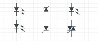
Turn the dial on the front of the multimeter clockwise to move it away from the "off" position. Keep turning it until you land on the diode setting. If not explicitly labeled, the diode setting may be represented by a diode circuit symbol.
The diode symbol visually represents both its terminals, cathode and anode
Connect the black probe to the cathode and the red probe to the anode.
Touch the black probe to the cathode end of the LED, which is usually the shorter end. Then press the red probe onto the anode, which should be long. Be sure to connect the black probe before the red probe, as the reverse may not give you an accurate reading.
- Make sure that the cathode and anode do not touch each other during this test, which can prevent current from flowing through the LED and hamper the results.
- The black and red contacts should also not touch each other during the test.
- Making the connections should cause the LED to light up.
Check the value on the multimeter's digital display.
When the multimeter's contacts touch the cathode and anode, an intact LED should display a voltage of approximately 1600 mV.
If no reading appears on the screen during the test, try again to ensure the connections are correct. If you performed the test correctly, this may be a sign that the LED indicator is not working. The method is convenient for all types of light-emitting diodes, regardless of their design and the number of pins. By connecting the reddish probe to the anode, and the dark probe to the cathode, a serviceable LED should light up. When changing the polarity of the probes, the number 1 should remain on the tester display. The glow of the emitting diode during testing will be small and on some LEDs in the brightest lighting it may not be noticeable. To clearly check multi-colored LEDs with several pins, you should know their pinout. Otherwise, you will have to randomly sort through the terminals in search of a common anode or cathode. Don't be afraid to test massive LEDs with an iron substrate. The multimeter is not capable of disabling them using the measurement method in dial mode. Testing an LED with a multimeter can be done without probes, using sockets for testing transistors. Check the brightness of the LED.
When you make the correct connections to test your LED, it should light up. After noting the readings on the digital screen, look at the LED itself. If it does not glow normally or looks dim, it is most likely a low-quality LED. If it shines brightly, it is most likely a high-quality working LED.
We hope that in this article you found all the answers to your questions.