The purpose of connecting an LED strip to a computer can be either modding the system unit or simply decorating an apartment on the eve of the New Year. Is it possible to connect an LED strip to a computer? Can. In this article we will look at how to implement this.
Before connecting, you should know 3 main problems that you may encounter:
- The supply voltage of the LED strip can be 12V, 24V, 220V. For obvious reasons, there is no point in using the last option. The computer does not have 24V voltage, so an additional converter is required. The best option is 12V.
- The computer power supply generates several voltage values. The most practical would be to use a voltage of 5V and 12V. It is these values that are generated by the most powerful part of the power supply and allow the connection of a powerful load. Based on the supply voltage of the LED strip, you need to use a 12V power supply output.
- To connect, you can use the USB port; it has a voltage of 5V with a permissible current of up to 500mA. Considering that the laptop has no other option to connect an LED strip, close attention should be paid to this option.
Let's look at how to connect an LED strip to a PC, what difficulties can be encountered in this case, and how to prevent damage to the computer when making homemade devices.
USB pinout
Everyone knows that when a phone is connected to a computer, it starts charging. This fact suggests that there is voltage present at the USB pins, which can be used to power the LED. A standard USB 2.0 connector has 4 contacts, two of which are needed for data transfer, and two for powering the connected device. Detailed USB 2.0 pinout is shown in the figure.
The standard load capacity of a USB port is 500 mA for current and 5V for voltage, which allows you to connect a whole line of low-current LEDs to the connector.
Connection diagram
The USB connector is perhaps the main part of the assembled structure. You can buy it in a collapsible case or use an unnecessary but working cord from any peripheral device. Depending on the distance of the system unit from the location where the backlight is installed, you need to calculate the length of the wire. Some keyboard models have an additional USB connector on the side, which can be used to provide backlighting.
LED
The connection diagram for one LED is shown in the figure. To implement it, you will need a USB connector, a resistor, a two-wire wire and a high-brightness LED. If the USB plug was purchased separately, it must be disassembled, freeing the internal part with solder contacts. Having decided on the LED, calculate the resistor resistance:
UPIT – supply voltage from the USB port equal to 5V; ULED is the forward voltage of the LED, which depends on the color of the glow; ILED – rated operating current of the LED.
You can read more about how to correctly select and calculate a current-limiting resistor here.
Now all that remains is to properly solder all the existing parts together and give the backlight an attractive look. First, using wire cutters, shorten the positive terminal of the LED and solder a resistor to it. Next, one wire is soldered to the free terminal of the resistor, and the second wire is soldered to the negative terminal of the LED. The leads, resistor and soldering points are hidden under a heat-shrinkable tube. To give a decent appearance, a larger diameter thermal tube is placed on both wires near the LED. On the reverse side, the connecting cord is soldered to the terminals of the disassembled USB connector. The wire coming from the resistor is connected to terminal No. 1 (+5V), and the wire coming from the minus of the LED is connected to terminal No. 4 (GND). Check that after soldering there is no short circuit with the second and third terminals and assemble the connector.
If a ready-made USB cord with a connector is used, then the free ends of the wires are stripped and the two outermost supply wires are connected using a multimeter. Then they are soldered to the LED through a resistor using the above method. Unused information wires are shortened and insulated to avoid short circuits. Now the backlight is ready for use.
LED strip
To make the backlight have a higher luminous efficiency, use LED strip. This is especially true for lighting the retractable shelf of a computer desk. The LED strip is glued to the edge under the tabletop, ensuring a uniform light flux on the surface of the keyboard. To power the tape from a USB port, you will additionally need a boost converter from 5 to 12 volts, which you will have to make yourself or purchase at an electronics store.
But it's easier to go the other way. The computer power supply produces the necessary +12V, which is present on the 4-wire molex connector inside the system unit. All that is required is to buy a mating molex connector with pins, solder a power wire of the required length to it and to the LED strip, which is routed through the back wall of the system unit. The plus of the tape is connected to the yellow molex wire, and the minus to any black one.
The load capacity of the +12V bus of a computer power supply is tens of times greater than that of USB, which makes it possible to make the keyboard backlight of the desired brightness.
Decorating computers, monitors or tables with LED strip lighting has become fashionable relatively recently. A USB backlight has appeared on sale, which connects to a 5V power source. This eliminates the need for a bulky rectifier that requires connection to a 220 V network and takes up extra space. Let's look at how to connect this tape to a computer.
Disadvantages and advantages
A traditional power supply has several disadvantages that are not obvious at first glance:
firstly, it needs to be selected correctly and the corresponding power calculated
An error can lead to the fact that it will either burn out, or the tape will shine dimly without ever reaching full brightness.
complex connection diagram
This especially applies to lighting with additional amplifiers, controllers, etc.
a bunch of wires that need to be pulled from the power supply across the room to the connection point to the tape
Plus, do not forget about the 220V wires - from the distribution box or switch, which must be used to connect the power source itself.
the need for nearby AC voltage 220V
dimensions and dimensions
If this is ceiling lighting, then a constant headache becomes the question of where to hide this not at all miniature-sized box. Often you have to make a special niche.
It is based on these shortcomings that many people think about connecting LED backlighting via batteries. The advantages of this solution immediately emerge:
This LED strip can be used to illuminate even those rooms where there is no 220V voltage (garage, barn, cottage without light)
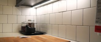
This creates convenient and safe lighting in the kitchen (especially the work surface of the countertop)
immediately eliminating the need to lay tens of meters of unnecessary wiring
Well, you no longer need to rack your brains about where to hide this big, heavy block
What is it like?
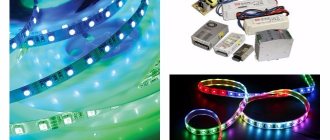
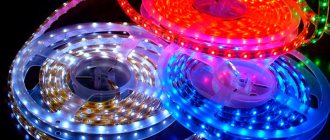
A USB LED strip is a chain of low-current LEDs designed for 5 V power supply. It is a highly specialized design, so there are few manufacturers of such lamps. Most of them are concentrated in the countries of Southeast Asia. Online stores (Aliexpress and the like) have a lot of offers for such lighting.
There are regular, single-color options, or multi-color RGB strips, for normal operation of which you will need a control device - a controller. All of them come ready to use, with a connector attached. All that remains is to plug the plug into the socket and place the tape in the planned location.
Characteristics of switching stabilizers
In video instructions, a specialist will tell you the main technical characteristics of modern switching stabilizers, circuit design and recommendations for their correct use. So that you don't burn it with your own hands during experiments.
Let's consider the optimal and modern one on LM2596. You will need to install only 4 radio elements. Analogs with similar functionality are ST1S10, L5973D, ST1S14.
There are several modifications of the microcircuit:
- fixed 12 V, LM2596-12, indicated at the end of the marking;
- adjustable version LM2596ADJ;
- the price in Russia for one is 170 rubles. In China, the entire assembled unit on LM2596 costs 35 rubles. including delivery.
| Parameter | Meaning |
| Input voltage, no more | 40V |
| Volts Output | 3-37V |
| Output current | 3A |
| Current protection tripping | 3A |
| Conversion frequency | 150 kHz |
When connecting a regular monochrome tape, you should adhere to three basic rules:
The same rules are fully applicable for multi-color RGB tape. However, there are some peculiarities here. They are connected with the use of an RGB controller in the connection diagram.
In addition, be sure to remember that full-fledged rgb backlighting can be made using SMD 5050 LEDs. They are the ones that implement the ability to change colors in one light source.
This is achieved due to the fact that the LED is assembled from three crystals. In all other types of SMD 2835, SMD 3528, one LED can shine in only one color.
Because of this, small dips in illumination may occur in the backlight, when neighboring LEDs simply will not light up and the strip of light will not look solid and continuous. Examples and disadvantages of such models can be found in the articles “Characteristics of SMD 3528 LED strips” and “Differences between SMD 2835 and SMD 3528 LED strips”.
The RGB controller is connected after the power supply. With its help, you can change not only colors, but also the brightness of lighting, different operating modes, the intensity of color changes, etc.
For the light-music mode, when colors run in different directions and replace each other, special controllers will be required. They are called DMX.
A certain length of LED strip can be connected directly through the controller. The maximum is 5 meters or 10 meters when connecting two sections of five in parallel.
What to do if you have multi-colored lighting more than 10 meters away? For the monochrome version, everything is solved by parallel connection of individual pieces. For example, you connect 3 sections of 5m each and have full illumination 15m long.
For RGB strips, it is possible to solder and connect 5-meter sections in parallel, but there are some nuances with direct connection to one controller.
Expert opinion
It-Technology, Electrical power and electronics specialist
Ask questions to the “Specialist for modernization of energy generation systems”
Power and driver in one module Ambilight is an ambient lighting technology invented and patented by Philips that provides background adaptive lighting on the company's television panels. Ask, I'm in touch!
Use Cases
The purpose of such LED lighting is purely decorative. Sometimes there are statements that installing LED backlighting on the back of the monitor is good for the eyes and reduces fatigue, but in this case the main purpose is the usual decoration, the lighting design of the device. Users install the LED strip in different areas:
- finishing the internal or external surface of the computer system unit;
- decoration of a retractable table for keyboard and mouse;
- monitor design;
- installation on the edges of a table or wall shelves;
- decorating other items located near a computer or laptop;
- creation of floor lamps, table lamps and other lighting devices.
If desired, you can come up with a lot of options for using such LED lighting. All of them do not require labor-intensive installation, do not load the computer’s power supply and allow you to obtain an attractive lighting effect. Another advantage can be considered the soft, non-dazzling glow of the LED strip. It does not create excessive brightness and does not disturb other family members at night.
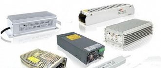
12V power supplies
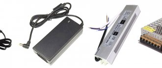
12V power supplies from electronics typically range from 6 to 36 watts. 10 watts is enough to illuminate the work surface with an LED strip in the kitchen. Such blocks are divided into 2 main types:
A voltage of 19V is widely used in desktop computer equipment, most often in laptops, monoblocks, monitors, and scanners. This category includes power supplies from printers; they are powerful, available in 16V, 20V, 24V, 32V.
The stabilizer on a chip like KREN 7812 (lm317), looks almost like a transistor, and when installed on a cooling radiator, can withstand a current of 1 Ampere. This option is outdated and cumbersome. To use the full power of a laptop PSU, you will need 5-6 of these (or 1 large one) and a large aluminum radiator for cooling.
A modern pulse stabilizer, miniature, does not heat up, and is as simple as 3 rubles. In Russian stores they ask for 600-900 rubles, the price is greatly inflated. The Chinese sell 3 amps for 50 rubles, 5-7A sells for 100-150 rubles, so I recommend ordering a couple of pieces on Aliexpress.
I recommend using a pulsed one, its efficiency is higher than 80-90%, it’s simpler and cheaper. Just don't buy a current source for the LM2596, you need a voltage source. To find in a Chinese online store, use the following queries:
| Parameter | Meaning |
| Input voltage, no more | 40V |
| Volts Output | 3-37V |
| Output current | 3A |
| Current protection tripping | 3A |
| Conversion frequency | 150 kHz |
Expert opinion
It-Technology, Electrical power and electronics specialist
Ask questions to the “Specialist for modernization of energy generation systems”
A connection to a 220 V network will be required if you want to change the color of the backlight; without it, all the diodes present on the tape will light up; Ask, I'm in touch!
Materials and tools required for work
To create and connect a USB LED strip you may need:
- the tape itself;
- wire or separate USB plug for soldering (best option);
- soldering iron and solder, ideally a soldering station with adjustable temperature and smoke extraction;
- scissors, knife or other tool for removing insulation;
- tester or multimeter;
- connecting wires;
- current-limiting resistor (the value is calculated based on the operating voltage of the LED);
- screwdriver, pliers (just in case).
Materials for fastening the tape are deliberately not included in this list, since different installation methods are used for each case.
USB pinout
Modern computers most often use USB version 2.0. They use 4 wires, two of which carry data and the other pair carry the plus and minus 5V power supply. In standard units, the plus wire is red and the minus wire is black. The contacts in a regular, flat socket (USB type A) are arranged in such a way that the data wires run in the center, and the power supply runs along the edges.
Important! For mini USB sockets of both types, the placement will be the same, and for USB type B, which are used to connect printers or other peripherals, the power is located on pins 1 and 4, located on the right, one above the other (if the beveled edges are on top). A continuity test using a tester will help you determine more accurately where the plus and minus are. When connecting, it is necessary to take into account the location of the contacts, since you will have to solder the plug, where everything is located in a mirror order.
Connection diagram
The schematic diagram of connecting an LED strip to a USB socket is simple - a current-limiting resistor is connected to the plus, to which the corresponding contact of the strip is soldered. The negative wire is connected to the negative terminal of the socket. It is important not to confuse the polarity. It must be remembered that when soldering the plug, the contacts will be mirrored relative to the socket.
First of all, it is necessary to calculate the value of the current-limiting resistor. The formula looks like this:
Where Upit is the supply voltage equal to 5 V;
U LED is the voltage drop across the LED, which depends on the length of the emitted wave;
I LED - current strength of the LED in operating mode.
The voltage drop across different LEDs can be clearly seen in the table:
| LED element color | Voltage drop |
| White | 3-3.7 V |
| Red | 1.6-2.3 V |
| Blue | 2.5-3.7 V |
| Yellow | 2.1-2.2 V |
| Green | 2.2-3.5 V |
| Orange | 2-2.1 V |
If the calculation seems too complicated, or its result is in doubt, you can use an online calculator. There are a lot of them on the network; to be safe, you should duplicate the result on two or three resources.
Once the rating has been calculated, you can prepare the wire or solder connector for use. If you use a ready-made USB cable, you need to leave one end intact (it will connect to the socket of a computer or laptop), and cut the second to length and strip the two outer contacts (these are the red and black wires, “+” and “–”, respectively). The other two wires carrying data should be shortened and insulated to prevent a short circuit.
If you plan to use a solder plug, it must be disassembled and soldered to the outermost contacts of the wire. You can do it simpler - immediately solder a resistor to the positive contact of the plug, and the corresponding electrode of the connecting cord to the negative one. Plus is soldered to the free contact of the resistor after assembling the plug. It is imperative to check whether the contacts are shorting with each other. They are located very close to each other, during soldering you can accidentally connect adjacent pins.
Installing RGB strip
In order to ensure the connection of the colored tape, it is necessary to solder the wires to the contact pads (there are only 4 of them). We suggest using a white wire for 12V, and connect the rest by color.
What kind of lighting do you prefer?
Built-in Chandelier
RGB tape diagram
It is necessary, as in the previous paragraphs, to strip the wires, remove any remaining adhesive tape and glue, and tin the contacts. Then we take a flexible cable (multi-core) and solder it to the pads of the LED strip. After this, we attach a heat-shrinkable tube to the wires and treat them with silicone.
Now let's move on to the most important part: connecting the colored tape to the controller. Installation can be done using bipolar transistors or mosfets. The connection is made accordingly, 1 wire to pin 1, the second to 2, and the third to 3.
If bipolar transistors are used, then we connect them in this order: the base connects to the controller pin 1, the collector to 2, and the emitter to 3. An important point: you need to install a resistor of up to 220 Ohms between the bases.
Main conclusions
An LED strip powered by a USB computer is a special type of LED lamps designed for decorative LED lighting of the computer itself or objects located near it. Various connection options are possible:
- separate LED;
- a whole 5V strip connected to the USB socket;
- standard 12 V LED strip connected to the molex connector of the computer power supply.
No special devices are required for connection except a current-limiting resistor and a plug. You will need a soldering iron and connecting wires. If you have your own options for connecting an LED strip to USB, post them in the comments.
At the moment, the market offers many options for organizing lighting for the place at the computer or the work area near it. One of the most optimal ones are LED strips, powered by a USB connector. In this article we will look at which LED strips can be connected to a USB port, connection diagrams, some nuances and features. We will also consider the technology of powering the LED strip directly from the computer power supply.
How to connect everything
In the box with the device you will find: clear instructions in English with pictures, a roll of RGB diode strip selected when ordering, the backlight control unit itself, an external power supply and cables for connection.
1. To begin, apply the tape to the back cover of the TV as close to the edge as possible around the entire perimeter.
2. Pay special attention to the corners; you can cut the tape and solder it at the joints or simply bend it carefully.
3. After this, connect the tape to the power supply according to the diagram.
4. Connect the logical cable to the control unit.
5. Connect the control unit to a free USB port on your set-top box.
7. We launch the application and can immediately check the operation of the tape by turning on the glow mode with one color or a random effect.
8. After this, we go to the application parameters, in parallel we count the number of diodes in the vertical and horizontal sections of our backlight.
9. We configure the corresponding parameters in the settings: set the number of diodes vertically and horizontally, the direction of the tape (clockwise or counterclockwise),
10. The LEDs Bottom Gap setting allows you to set an inactive area under the TV stand, and the First LED Offset parameter allows you to select the location of the first diode for different options for gluing the tape.
11. Below you can configure the screen refresh rate, the color capture area and the quality of the reproduced effects (the frequency of tape color changes).
After entering all the parameters, you can check the correct operation of the backlight in Screen Capture Mode .
▣ For correct operation of the backlight in different applications, we recommend using a third-party player – Vimu Media Player. In its settings, you need to activate the Output video to texture .
▣ To work when watching IPTV, use OTTPlayer with the Decoder media player .
Why connect an LED strip to a computer?
In areas where computer equipment is located, it is often necessary to install additional lighting. For example, not to use the main lighting of the room. It may interfere with other family members when using the computer at night. Or switch off to save money. The light from the monitor may not be enough. Also, the presence of backlighting eases the strain on your eyes when working on a PC.
Powering the LED strip from a PC allows you to solve these problems. Installation of the tape is possible in any necessary place and to perform various functions:
- monitor backlight;
- keyboard backlight;
- additional lighting of the work area.
- decorative design of a table or room interior.
The tape can be powered via a USB output or directly from the computer's power supply. The use of such power sources eliminates the need for:
- stretch additional wires, of which there are always plenty near the computer and often get tangled;
- take up space in the outlet, which is also sometimes not enough, especially if you have additional office equipment.
Using a USB LED strip allows you to save power consumption, since the strip uses little - up to 5 W.
Which LED strips can be connected to a PC via USB
At the output of the computer's USB port, the voltage level is not high (up to 5 volts). There are basically two options for connection:
- Connecting a ready-made LED strip model with a built-in converter and USB plug. This factory-made tape implies an input voltage of 5 V; for operation you just need to connect it to a USB port.
- The second option is to assemble a circuit using a 12 V LED strip and a voltage level converter from 5 V to 12 V.
Criterias of choice
The main selection criterion is the type of built-in LEDs:
- SMD chips are equipped with single-color crystals and, accordingly, can glow in only one color, depending on the shade chosen when purchasing;
- RGB has 3 types of crystals corresponding to the primary colors, mixing which with the help of a controller you can get lighting of all the colors of the rainbow.
When choosing between these two main types, you need to understand that the first option is three times cheaper than the power supply:
- When purchasing it, as a rule, they are guided, first of all, by the voltage required to power the light source, which is usually indicated on its packaging. Based on this parameter, choose between a 12 and 24 V energy source.
- An equally important selection criterion is the power it produces, which should have a margin relative to the power of the lighting element of about 25%. The power consumed by the strip depends on its length, as well as on the strength of the LEDs themselves. For example, a 60-watt unit, taking into account the reserve, can power no more than two pieces of tape of 24 watts each. To find out the power consumed by a specific piece of a strip of any length, you need to multiply the power per linear meter of the device indicated on the packaging by this length.
It is very important to choose the right transformer unit, since a device that does not meet the minimum power requirements will not allow the lighting to turn on, and one that does not have a reserve will overheat and sooner or later fail. A device with too much power and voltage surplus will shorten the service life of the diodes themselves in the backlight.
Connection features
Connecting the LED strip via a USB port is carried out if it is impossible or unwilling to get inside the computer, as well as when using a laptop. When assembling the circuit, it is necessary to take into account that to power the tape, a voltage level of 12 V is required. To do this, you need to make or buy a ready-made voltage converter from 5 to 12 V in a radio parts store.
It is worth considering that the USB port produces no more than 500 mA. When introduced into the converter circuit, the current is reduced to 200 mA. Therefore, you should use an LED strip with the same or lower current parameters.
To assemble the converter, you can use a factory PWM controller, for example LM2577, this will reduce the number of parts of the converter. The following parts are also required according to the diagram: USB plug, connecting cord.
This circuit is considered universal and makes it possible to obtain the desired output voltage. Its parameters depend on resistors R1 and R2. The result is a pulse-width converter. The capacitance of the capacitors at the input and output of the power supply must be in the range indicated in the diagram. These capacitors are designed to smooth out DC voltage ripples.
The resistor and capacitor at pin 1 are the frequency-setting circuit. Their parameters must be strictly observed according to the scheme. The inductance of the coil between points 4 and 5 should be clearly 100 μH. The diode must meet special conditions. It must have high performance, and also a slight reduction in voltage at the junction. The ideal option is a high-frequency Schottky diode. The brand of diode is not very important, since this circuit has an insignificant level of voltage and current.
Next you need to connect the wires and the USB connector. To do this, it is convenient to use a detachable USB plug. It has 4 contacts. To connect, you only need two on the edges, which provide power. Their polarity can be determined with any voltage measuring device by connecting the plug to the socket.
The circuit is mounted on a printed circuit board made of foil fiberglass, and as a result the device has approximately this appearance:
If you have certain skills and knowledge, it is not difficult to assemble such a circuit. The most important thing is to strictly follow it and observe the location of the parts.
Set contents
When purchasing an LED strip, you may want to pay attention to ready-to-use lamps. This is an easier way to illuminate areas in your home.
With some diligence, you can now find lighting fixtures to suit every taste and budget. In addition, sometimes assembly from separately purchased elements can be much more expensive than ready-made products. The tape itself cannot provide lighting without additional devices. For it you should also purchase a power supply, an adapter, an adapter and a certain amount of wire with which it all is connected. For a professional this will not be difficult. But an amateur will have to write down all the required characteristics, draw a connection plan, put all the parts together, try not to mix up the wires and thus not destroy all the purchased materials. And the result may be far from the plan.
At the same time, the master, when assembling the lighting, is able to control the quality of the material used, the work on the installation of the structure and placement. If you want to become a real master and decorate and ennoble your home as much as possible, you need to start small and simple, gradually moving on to more complex elements.
In conclusion, it should be recalled that when assembling more economical lighting, you should not purchase cheap materials. As they say, the miser pays twice, or even more. There are many offers from Chinese craftsmen on the Internet. It’s just that the lack of any guarantees, and sometimes even markings, makes you wonder whether their use will lead to a sharp reduction in service life or to more irreparable problems in the form of an accidental fire or harm to health. It is worth paying attention to the choice of not only the material itself, but also the manufacturer.
Connecting an LED strip from a PC power supply
The technology for connecting from a PC power supply is a little simpler than the previous method. With this connection, there is no need to break the warranty seal on the power supply and disassemble it. Almost every power supply is equipped with additional connectors. The wires can be like this:
Connectors of types 1 and 2 are suitable for connecting the LED strip. The first one is used to connect a practically unused “flop” for floppy disks. Number 2 for connecting a hard drive and CD/DVD-ROM. Both jacks have 12 volt output and are available for use. To connect, you need black and yellow wires. Black is a minus.
The connection technique is extremely simple; the necessary wires are disconnected or simply bitten off from the selected connector and soldered to the LED strip, observing polarity. But in the future, nothing can be connected to this connector.
If you plan to use the connector or simply don’t want to break the circuit, you can buy an adapter and cut the wires on it.
The power supplies of modern computers are quite powerful and you can connect LED strips up to several meters long to them. Data on power and current are indicated on the power supply itself. In most cases, there is always a power reserve that can be used to connect an LED strip.
When calculating the length of the tape, the following table will help, since the tapes do not always contain information about the consumed load.
Approximate calculation of the length of the tape. If the power supply has a current reserve of 4 or more amperes, then you can safely connect an SMD 3528 tape with a density of 120 diodes per meter, 4 meters long, or a 3-meter SMD 5050 with a density of 60 diodes.
The length and type of tape are calculated similarly when connected from a USB port.
How to make a backlight for a PC with your own hands?
They operate in the following order:
- Based on special marks, a fragment of a given length is cut from the tape,
- Treat the contact pads (lamellas) on it with alcohol.
- Using a puller or a utility knife, remove the ends of the wires from the insulation to a length of 5 mm.
- The exposed area is twisted into a tourniquet.
- Dip the stripped ends of the wires into rosin.
- Flux is applied to the contact pads of the LED strip using a toothpick.
- Take a small dose of solder with a heated soldering iron tip and transfer it to the lamella. To avoid burning it out, the contact time should be limited to 1 second.
- Solder tubercles are formed similarly on other contact pads of the connected tape.
- Brown deposits from the flux are removed with a napkin. If it has time to harden, this will require alcohol.
- Use wire cutters to shorten the bare ends of the wires so that they are equal in length to the lamellas. Otherwise, a short circuit may occur when the wires are bent.
- The core is placed on a tubercle of solder and pressed into it with a heated soldering iron. Contact duration is limited to 1 second.
- Before the solder hardens, ensure that the connection remains motionless. This takes a few seconds.
- Having soldered all the wires, clean the contact points from flux with a cloth soaked in alcohol.
- Place a heat shrink tube over the assembly and heat it.
- Cut off the SATA connector from the adapter.
- Strip the ends of the yellow and one black wires. The rest are trimmed and isolated.
- Heat shrink tubes are put on.
- Twist the wires from the LED strip and the connector in compliance with the polarity. Then the connection is soldered.
- Slide heat-shrinkable tubes over the contact points and heat them with a hair dryer, match or gas lighter.
- Insert the adapter plug into the Molex connector.
The RGB strip is connected in the same way. To avoid confusion, it is recommended to solder wires in insulation of different colors to the “cons”. Next, connect the cores from the Molex-SATA adapter to the RGB controller. On the other hand, wires from the LED module are connected to it.
The backlight assembled in this way lights up simultaneously with the computer startup. To be able to extinguish it during the day, a microswitch with a remote control function, for example, from a smartphone, is soldered into the gap of one of the wires.
The installation process is simplified if you purchase a piece of tape with wires already connected.
Ready solutions
For those who do not want or are simply unfamiliar with the world of electronics, the modern market offers many ready-made options for LED strips connected to a USB port. They may differ in appearance, but in general they work on the same principle. Examples of ready-made solutions:
The first option is an RGB strip with a connected RGB converter. The set includes a control panel that allows you to adjust the brightness of colors and their shades. The second option is a 30 cm long monochrome LED strip. Both options simply connect to a USB port and do not require additional devices.
An LED strip connected to a USB port is a good option for organizing lighting near a computer. Its use allows you to save on energy consumption; it does not take up much space, like a table lamp. The technology for connecting an LED strip to a computer is generally simple and does not require serious financial investments. In addition, there are many already assembled models that can simply be connected to a USB port.
Features of installation of monochrome light strips
Monochrome LED strips can have different shades, but the most common are those with a white glow, which, in turn, are divided by temperature conditions. For example, stripes with warm white light, closer in shade to incandescent lamps. This pleasant soft glow of a slightly yellowish tint is used for bedrooms, living rooms and children's rooms. If we talk about cold light, then this is most suitable for office premises.
PHOTO: designmyhome.ru Monochrome white tape in the interior looks pretty good
To connect a monochrome LED strip, only 2 contacts are required: plus and minus. Their installation is much simpler than RGB, however, the effect created by the operation of such a strip cannot be called unusual. Let's try to take a closer look at how a monochrome LED strip is connected.
Instructions for connecting a monochrome light strip
To make the step-by-step installation instructions easier for the reader to understand, we will illustrate all the steps performed with photo examples.
PHOTO: yastroyu.ru Low-power tape can be used as a backlight
Let's consider the simplest option, when all equipment is purchased simultaneously as a set. In this case, you will not need a soldering iron or additional connectors. All necessary plugs are already installed on the equipment.
First, let's look at what the kit is. This:
- LED strip 5 m long;
- dimmer with remote control for monochrome tape;
- power supply (in our case, its power is 6 W).
PHOTO: youtube.comKit for arranging lighting: tape, dimmer, power supply
After unpacking, you need to connect the LED strip to the dimmer, and then to the power supply. This is extremely easy to do; you just need to insert the plugs into the appropriate sockets.
PHOTO: youtube.com Connecting all elements of the circuit - now you can connect the power supply to the network
The LED backlight is turned on and off using the remote control. To do this, it has On and Off buttons.
PHOTO: youtube.comButtons for turning the LED strip on and off
Additional buttons, in our case orange-brown, adjust the intensity of blinking of the strip LEDs from the slowest (top) to the fastest (bottom). This option can create the necessary atmosphere during any celebration or dance.
PHOTO: youtube.comButtons for adjusting the intensity of the strobe mode
Also on the remote control you can find buttons to enable other modes, such as cyclic slow or accelerated fading. If you need to manually dim the lighting intensity a little, then there are keys at the top for these purposes. This, in fact, is the dimmer itself.
PHOTO: youtube.comManual dimming buttons on the remote control
Connecting two or more monochrome tapes
There is no particular difference in connecting additional tapes. However, there are a couple of nuances that should not be ignored. Firstly, LED strips cannot be connected in series, making strips of them more than five meters long. Such actions will lead to overheating and burnout of the tracks located closer to the power supply due to the increased load on them. Therefore, only parallel connection is suitable here.
PHOTO: carnovato.ru Monochrome tape switching diagram
Secondly, the power supply must have an output power corresponding to all LED strips connected to it. Ideally, the output power of the rectifier should exceed the consumed power by 30%. Otherwise, the power supply will overheat and eventually fail.