The 12V power supply for the LED strip provides the need for reduced voltage when using LEDs for lighting residential premises or streets. These devices can be of any length, but their energy consumption will be minimal. The devices have increased light output and efficiency.
Operating principle of the lighting device
The LED strip connection diagram is easy to use. The device is powered by 12v power sources. To convert the mains voltage to 220V, you need a power source with a current stabilizer, that is, a driver, which is an adapter. These devices, which have differences, are characterized by different ways of functioning.
Many types of LEDs require a voltage of about 2-3 V, and LED devices are powered by 12v sources.
Single LEDs are connected in series, and the power supply circuit itself operates in the presence of a limiting resistor. It is current that is required to power the LED. When it drops in the circuit, current flows through all the elements, that is, these same 2–3 V are needed for the operation of the device.
LEDs are devices that are sensitive to the amount of current that needs to be stabilized. Otherwise, exceeding it will negatively affect the service life of the device. Having figured out what kind of power supply is needed for LED lighting, you can ensure stabilization of the voltage of the current source.
All semiconductors are characterized by an increased level of temperature dependence. Tape is the basis of electronic temperature meters. If the temperature of the external environment changes, then at the same time there is a change in the current flowing through the lighting device, provided that the input supply voltage of the LED strip is constant.
The use of stabilizers is due to the fact that LED lighting is often necessary where the range of temperature fluctuations is not too high. Another advantage of using stabilizers is the parallel connection of lighting fixtures. When the voltage drops in such a circuit, the current begins to increase. Drivers are usually used for outdoor lighting because temperature fluctuations are large.
Power supply power
The power of power supplies for LED lamps is determined by a similar indicator of the total load of all devices connected to the circuit. The permissible power level limit may be violated, which causes unstable operation of the device or overheating. A power source whose power level is below the maximum permissible can be connected to the tape.
The power reserve of the power supply for the LED strip is large, so its cost increases. The principle of current stabilization means that its value remains unchanged for different output voltage options. For example, according to Ohm's Law, a 12v lamp with a power of 1W consumes a current of 0.83 A.
An equal amount of current is provided by the driver, connecting to which the LED lamp at the output of the power source will be 12v. If 2 devices are connected to it, which are connected in series, then the current at the output of the circuit is 24V, if 3 lamps - 36V.
They can be connected further until the output voltage is limited, after which the current also drops.
You cannot connect several LED lamps to the driver at once, since the output current must be divided proportionally between the devices. The use of drivers is limited by the complex design of the lighting system, which excludes the possibility of changing the number of connected lighting fixtures.
Types of Humidifiers
It's time to launch! Diagnostics Possible causes of breakdowns must be excluded by performing simple tests with the disassembled device: Plug in the power plug and check whether the fan or cooler is working.
Also, a decorative grille for the fan wouldn’t hurt: it’s both beautiful and safe. After sending, the data is displayed on indicators based on the principle of dynamic control. Caring for an air humidifier The season for using an air humidifier is autumn-winter, but in some areas this unit has to be used almost every day.
It turns out that all pediatricians will confirm that moist, cool air is the safest for the spread of winter colds - the mucous membranes do not dry out and a barrier from bacteria is maintained. In this situation, you need to replace the fuse in the plug. We screwed on the fan and installed the handset.
Therefore, during operation, humidifiers become clogged and clogged, and using a contaminated humidifier greatly reduces its useful life and can cause undesirable results. Otherwise, it is recommended to wash it with soapy water, let it dry and put it back in place. The method used by fireplaces that imitate orange flames is considered advanced.
See also: Laying cables in the ground document
Repair of backlight and charging in T72H3G and TEXET tablets
Power supply B - 12V 3A. When it does not rotate, replace the motor. It is necessary to check the condition of the feed motor and ultrasonic type pressure conversion membrane. Unpleasant odor If you notice an unpleasant odor when the humidifier is operating, the membrane is dirty.
RUZIK40 Just a heap - a flaw in the circuits of air humidifiers on a piezo element: Only for registered Only for registered By typing into Google, in the image search - “Humidifier schema” or “air o swiss schema”, you can find more similar circuits. An inflamed mucous membrane, a dry nasopharynx, and sometimes even a cough are all possible reactions of the human body to too dry air. Checking the operation of the indication after wiring the MAX The use of the MAX microcircuit and seven-segment indicators in my case is justified, first of all, by their presence and secondly by the size of the indicators. Deep cleaning Deeper cleaning is required every three days.
The gold and silver stripes are units and tenths of an ohm, respectively, but their position on the resistor is unclear, in short, post a readable photo next to the ruler, so that you can judge its size, then I can give you a more accurate advice. When a control signal is applied to it, vibration begins, and the water literally whips into fog.
At the same time, fungi and microbes are killed inside. The reservoir must be Daily cleaning To clean the humidifier, you need to turn it off and empty the reservoir of any remaining water. Humidifier repair.
Purpose of the power supply
When choosing a LED strip kit for interior decoration, you should take into account its features. The device cannot be connected directly to an outlet, like a simple light bulb, since the voltage of the strip is not 220V, and when it is plugged into a regular outlet, it will stop working.
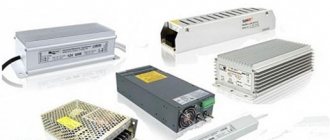
If an incandescent lamp is powered from a 220V network, then to reduce the voltage in a standard network to 12 or 24 volts, a power supply for the LED lamp is required. There are several types of such devices.
Power supply for LED lamps. The advantage of the device is its minimal size, but the disadvantages include:
- high price;
- difficult heat exchange;
- power limitation (there are no devices for lighting 12V 100W or more).
An expensive model of the LED lamp power supply has an aluminum housing. Among the advantages of this transformer are:
- reliability;
- tightness;
- strength.
The scope of use of this device is related to outdoor illuminated advertising. Thanks to the presence of an aluminum housing, normal heat exchange is ensured. The power source is resistant to the negative effects of various factors:
- moisture;
- sudden temperature changes;
- direct sunlight.
An open type power supply is a budget option that is especially popular. Often used when installing home lighting using LED strips. The downside is the size of the device, which can be 2 times larger than previous options.
The device has an unaesthetic appearance and lacks protection from moisture and dirt.
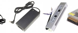
The network compact power supply for LED lamps is a miniature device with a power of no more than 60W, the inclusion of which does not require installation. The devices are easy to use because the tapes are connected to a power supply and then plugged into an outlet.
Recommended Posts
What is sold everywhere can be roughly divided into four categories: board balancers that provide charging, yes, they are also considered BMS devices, certain combinations of the above options, up to combining everything into one device. The more functional and extensive the protection, the longer the operating life of your device. battery Charging and balancing I left the original charger from the screwdriver, it just produces about 17 volts at idle. You cannot close terminals with different polarities both on the batteries themselves and on the electrodes; it is recommended to tin them or solder them before installing the structure. By the way, these legs are very good and, oddly enough, the quality of the legs is that they are elastic and do not slip at all.
I measured with resistors, they added a couple of amperes, but the stand was already disassembled.
Lithium-based batteries charge in two stages.
The advantage is that there is no need to use external power. The implementation of this algorithm is also possible using conventional laboratory power supplies.
The assembly of a LiFePO4 battery consists of a series-parallel connection of the cells of the device.
A parallel connection does not require balancing of cells across parallels, it involves the summation of capacitance, and the voltage parameter is unchanged. I also left vertical cutouts for the wires, which should extend from the inter-can connections beyond the lid.
Among the accidents that have occurred with batteries, for example, electronic cigarettes, only a small percentage is due to manufacturing defects; most often, malfunctions arise as a result of improper operation. How to connect a BMS (PCM) board and assemble a 12V lifepo4 battery with your own hands
Power supplies for lighting devices
The variety of lighting devices, including floor lamps, chandeliers, table lamps, etc., amazes even those people who have a rich imagination. The emergence of the latest technological developments not only provides high-quality lighting, but also saves energy resources to the maximum extent.
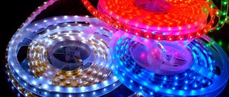
Alternative products are LED strips, which are energy-saving lighting devices. The choice of lamps, the production of which is based on progressive LED technology, is quite wide. These devices have a good design and high-quality technical characteristics.
The use of LED lighting is widespread in advertising, landscape and interior design, car interiors, equipping household appliances, etc. A large assortment of such lamps allows you to choose the appropriate option, be it 40w by 300w or 24w by 250w.
Any selected lighting device requires connection.
For many it may raise a lot of questions. The power supply is the main component of the LED system, which is a compact transformer capable of providing power to the LED strip. Miniature dimensions ensure discreet placement of this device in various suitable places.
DIY power supply
Only a professional can assemble a switching power supply for an LED panel with his own hands. It is easier to make a circuit using a transformer, since you cannot connect an LED strip without a power supply. This device usually reduces the mains voltage from 220 volts to the required value.
The simplest situations can be associated with the use of a conventional resistor, the resistance of which should be high.
This will ensure stable operation of the LED strips.
Creating such a circuit is not easy, since it will be necessary to take into account the loss of part of the electrical power. To compensate for losses, LEDs are connected to low-voltage sources that stabilize the output current.
LED lamps are produced with a power supply built into the design itself. When creating them, the power of the transformer that reduces the alternating voltage must be taken into account. At its output it is 12–20V. The power supply for the LED strip 24V or 12V is selected depending on the type of device. The LED strip kit has a transformer in the form of a stand-alone module.
When creating a power supply for a 12V 250W or 12V 220 volt LED strip, you will need to prepare a full-wave rectifier with a filter capacitance. The device's stabilizer has a simple 7812 microcircuit that provides an output current of no more than 1.5 A.
To increase the power supply circuit, it should be supplemented with an external transistor.
After connecting the LED strip to the power supply, high-quality insulation of all contacts that need to be hidden under it is ensured. Reliable protection against accidental touches is provided by a small piece of cable duct of the required thickness. If insulation is performed with ordinary electrical tape, the device will have an unattractive appearance. The kit includes protective covers for the power supply for the 24v or 12v LED strip; they will ensure the required level of electrical safety.
S-180-12 180W 12V / 15A power supply in an unusual form factor
In the last review of the power supply, I mentioned that I ordered two units for review, today I will talk about the second test subject. In its own way it is interesting and well made, but not without its shortcomings. All more detailed information, as always, is under the cut. I already had a review of a power supply with the same power and the same voltage, but in this case these power supplies are radically different, which prompted me to take it for a test. The review will be in the same format as always, but the comments and conclusions will be completely different.
I’ll start today in an unusual way, with packaging :))) The power supply, like last time, had its own cardboard “house”. But this time there was a marking on the package - Led power supply, although it has nothing to do with powering the LEDs since it works as a source of voltage, not current, but in this case it does not matter much. There is also a power marking on the side, and I immediately noticed that at first it was highlighted - 150 Watts, then crossed out and marked - 180 Watts, but we will return to this later.
The first distinguishing feature of this power supply is its form factor. The power supply is made on the basis of a U-shaped aluminum chassis that acts as a radiator; usually power supplies are made in the form of an L-shaped chassis with a perforated casing. This design should improve cooling of power elements and reduce the size of the block, but the heating test will come later.
The dimensions of the power supply are very modest, length 200mm, width 59mm, height 36mm.
At the ends of the block there are connectors for connecting 220 Volt power + grounding and 12 Volt output. The output terminals are made double, with two contacts for each polarity. This is caused by a rather large output current, up to 15 Amps; in this option it is more convenient to connect the load.
Each terminal block has a protective cover. In a previous review of the 180 Watt power supply, I was asked if the lid opened all the way, as a person had problems with it. The lid, although it has rather tight latches, opens at 90 degrees.
The manufacturer claims the following characteristics: Input voltage - 110/220 Volts ± 15% (which is strange since the power supply does not have a voltage switch) Output voltage - 12 Volts Output current - 15 Amps.
Since there was nothing else interesting outside, I climbed inside. The unit is extremely easy to disassemble; there are four screws on the sides, unscrewing which you can easily remove the top cover. The first thing that caught my eye was that the power supply was assembled using single-cycle circuitry. In my personal opinion, a power supply with a power of 180 Watts assembled according to this scheme is already on the border of good and evil. The fact is that at low powers such a circuit works perfectly, but at high powers push-pull, bridge or half-bridge ones already “rule the roost” (this circuitry is used in most computer power supplies). This BP is located approximately on the border of the division of “spheres of influence”.
The power supply survived the first turn-on quite normally, which in itself is pleasant. It was initially set to 12.21 Volts (only later did I understand why). The adjustment range is not very large, minimum 11.75, maximum 12.63. After checking the adjustment range, I set the power supply to the stated 12 Volts.
Several photos of the main components of the power supply. 1. Surge filter, this time there is a thermistor that protects against current surge when the power supply is turned on, there is a place for a protective varistor, but they “forgot” to solder it. 2. The input capacitor has a capacity of 150 μF, looks more like a proprietary one, and is designed for a maximum temperature of 105 degrees. If it weren’t for the reduced capacity, then I would say that it’s excellent, but otherwise it’s good. 3. The high-voltage transistor is pressed using an L-shaped plate. there is a paste, and it looks like silicone. 4. Two diode assemblies are installed at the output, also pressed with a metal plate through the paste, but to the other wall of the housing.
Let's look further. The board is screwed onto one mounting screw, inserted into the slots of the housing itself, and can only be inserted and removed together with a dielectric insert. You can see that the board is almost empty; only large elements are installed on top of it. This is how branded power supplies are usually made (at least that’s what I remember).
Printed circuit board.
A couple of more detailed photos of the printed circuit board. The secondary side, precise resistors are used, this is good, the wiring of the feedback circuit is also interesting, it is clear that they still thought about the routing. By the way, the power supply is made by the same manufacturer as the previous one for 24 Volts.
Primary side.
An unknown to me LD7575 was used as a PWM controller. But I noticed that the manufacturer placed a ceramic capacitor parallel to the electrolyte in the power circuit of this microcircuit. This happens quite rarely, but in vain. The current measuring shunt is made in the form of six resistors connected in parallel.
The circuit diagram is slightly different from the previous power supply. In the diagram, some positions have a designation of the form - 22 (11) and a serial number of the element consisting of several numbers. This means that several parallel elements are installed; the total value is given in brackets.
Selected photographs of the main components of the power supply. 1. Input power filter elements, noise suppression capacitor and inductor. 2. A thermistor to limit the starting current and a KBL406 diode bridge, this time a 4 Ampere 600 Volt diode bridge. 3. Additional noise suppression capacitors, correct Y type. 4. High voltage transistor svd12n65f. The transistor is in an insulated housing, designed for current up to 12 Amperes and voltage up to 650 Volts. In my opinion, it could have been installed more powerfully, but the test showed that everything was in order with it.
1. The interwinding capacitor is also of the correct Y type, which is rare these days. Next to it there is an empty space for installing the same capacitor, connecting the minus of the output circuit to the power supply housing, but it was also “forgotten”. I won’t say that it is very important, but it would not be superfluous. 2. Output diode assemblies MBR20100CT, no questions, the parameters correspond to the output current and voltage of the power supply. A few words about the transformer. Made correctly, it is clear that the primary winding is made of two wires and is divided into two parts (this is desirable to improve the connection between the windings). The output winding is made of four wires, although at such currents a Litz winding looks better.
The output capacitors are made up of five pieces. Before the choke, three pieces of 1000 μF for 25 Volts are installed, after which there are two pieces of 1000 μF for 16 Volts. I think it was worth installing all capacitors at 25 Volts at least. And ideally, before the choke, 35 Volts, after - 25 Volts, but this is rarely found even in branded power supplies. The output choke has been detuned; the location allows you to install a choke with a higher inductance and designed for a higher current. I would recommend replacing it with a more suitable one. A small measurement of the capacitance of the capacitors showed that the indicated and actual capacitance corresponded.
Well, actually, we’re done with the review of the design and elemental base, now we can safely move on to testing. For this purpose, the same “stand” was assembled as in the previous review. It included: Experimental power supply. Electronic load Oscilloscope Multimeter Non-contact thermometer
The testing methodology is almost standard. Switch on, load, warm up for 20 minutes, increase load current, warm up for 20 minutes, etc. until we hit the maximum current, or until the power supply makes its last squeak. The oscilloscope probe divider was in the 1:1 position, the oscilloscope division value was set to 0.1 Volt. 1. First check at idle speed, output voltage is 11.98 Volts. 2. Increasing the load current to 3 Amps, the voltage dropped sharply to 11.65 Volts.
After I saw that the output voltage dropped sharply under a relatively light load, I immediately remembered that it was originally set to 12.21 Volts. Apparently the load resistors located at the output of the block do not quite cope with their function and the output voltage rises at idle. I had to adjust the output voltage to 11.99 Volts at a current of 3 Amps. I didn't touch the regulator anymore.
1. Load current 6 Amperes, voltage 12 Volts, ripples occur with a voltage of about 0.4 Volts 2. Load current 9 Amps, voltage 11.92 Volts, the range of ripples has hardly changed, but they have become more frequent.
1. Load current is 12 Amps, voltage is 11.84 Volts, ripple voltage is about 0.5 Volts 2. Load current is about 14 Amps (the load no longer provides), the voltage dropped to 11.8 Volts, but the ripples have already increased quite significantly and amounted to 0.65 Volts.
As I wrote above, data on the temperature of the components was taken every 20 minutes. The first value is idle after about 20-30 seconds of running under a current of 10 Amps (this is how it happened), the next ones were taken before the next increase in current. The last value is an additional 20-minute warm-up to assess the dynamics of temperature growth. The total test time was 2 hours. Temperatures were measured: High-voltage transistor, transformer, output diodes, output capacitors. The temperature of the output diode was taken to be the value with the higher temperature (one assembly had a temperature several degrees higher).
At almost the maximum load current, the power supply noticeably overheats, so during operation you should not count on a current of more than 12 Amps.
At the end of the experiment, I took a picture of the heating of the entire power supply as a whole; unfortunately, I don’t have a thermal imager yet, so that’s the only way.
Summary. pros
Nice and well thought out design. Having a power filter with the correct types of capacitors. Most of the components are selected correctly and according to the power of the power supply.
Minuses
High ripple level can be improved by replacing the output choke. Large heating at maximum current, unfortunately, cannot be corrected by simple modifications.
My opinion. At the very beginning, I wrote that I would return to talk about the power of the power supply, which was originally indicated on the packaging. I believe that the initially indicated 150 Watt is the power at which this power supply can operate quite safely. I was pleased with the good design, the presence of a full-fledged power filter, and the correct capacitors (affects safety). But the high temperature upset me, and while it is common for semiconductors, it is dangerous for the transformer and output capacitors. The capacity of the capacitors, in my opinion, is somewhat underestimated and is also more suitable for a power of 150 Watts, rather than 180. The result is a completely normal, well-made power supply with a power of 144 Watts, or, in other words, 12 Volts 12 Amps.
I hope that the review was useful and will allow you to make the right choice.
The product was provided for writing a review by the store. The review was published in accordance with clause 18 of the Site Rules.
Using additional adapters
The lighting will be complete only if the appropriate connection diagram is followed. Before connecting the LED strip to the power supply, you should take care of a device that allows you to change the intensity of the lighting device. If any of the circuit elements are connected incorrectly, the operation of the backlight will be disrupted.
A dimmer, or an additional adapter for a 12-volt LED strip, is a device that allows you to control the brightness of the light. The use of this device is the main reason for the popularity of LED strips.
The power supply for the LED strip is connected with a dimmer, which eliminates the difficulties of using it.
The use of this circuit allows you to control the flow of light. The dimmable LED strip is connected simultaneously with the main and additional adapters, that is, a dimmable power supply is needed.
Before calculating the connection diagram, it should be taken into account that 12-volt tapes have different power ratings. Since choosing a power supply for a chandelier differs from choosing a transformer for an LED strip, two indicators should be taken into account:
- power;
- voltage.
The first parameter is determined by the length of the led or rgb strip, and the second is about 12 or 24V. To dim the tape, you will need to correctly connect not only the transformer to it. The circuit must include a dimmable power supply, the power of which is 12 or 24V.
This involves using a certain type of dimmer.
For example, for an RGB tape that has 3 colors, a special adapter is required that allows you to mix colors and turn them on separately. If the dimmable power supply is selected correctly, the backlight adjustment functions.
Connecting LED strip
The LED strip turned on in laboratory conditions looks like this:
2 pieces of diode strip - power is applied. +/- polarity matters.
When connecting power to an LED strip, power polarity , as in the entire semiconductor world. Unlike incandescent lamps and heating elements, where polarity does not matter. However, if you turn on the LED strip in the wrong polarity, nothing bad will happen - it simply won’t light up. You can safely check the correct connection by swapping the power wires.
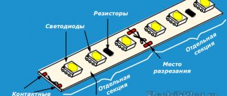
If you need to cut a piece of tape from a whole piece, you have to solder , that is, solder the power wires to the contact pads that are located at the ends of each elementary piece. There are also scissors drawn there. The wire for connecting the LED strip should be used thin, with a cross-section of no more than 0.5 mm2, as shown in the first photo of the article. Before soldering, clean and tin the contact pads. Use a soldering iron with a power of no more than 40 W, preferably 25 W.
And remember, the soldering point is the most unreliable place in the entire structure; it must be protected from mechanical overloads!
For some types of tapes, there are special connectors on sale that fit onto the tape, without the need to use soldering.
The photo below shows an example of how to connect an LED strip through a connector:
Connectors for connecting Jazzway LED strip
LED strip connected via connector
LED control
Before connecting the LED strip by placing it on the surface, you need to prepare the power supply for connection. For example, it is enough to use an open type transformer. Its body is a perforated metal box. Air circulates through its holes, cooling the radio components.
There are models with a fan (cooler) located inside the case.
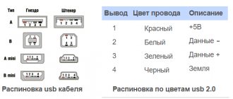
Before choosing a power supply, it is important to consider its labeling. Along with it, the purpose of this device is indicated. The block diagram assumes that the wires are connected correctly:
- L—phase;
- N - zero - bp input. Terminals for operating the device from a 220V network;
- G - ground wire. The terminal remains free if there is no grounding in the house;
- +V and -V are output. The terminal provides voltage conversion to 12V.
A dimmable power supply for 24 or 12V LED strips must have a power indicator, that is, a green light bulb. The presence of a rotary mechanism provides an adjustable output voltage level in the range of 12–13 Volts. It is designated "V adj".
Before choosing a power supply for the LED strip, it is better to install more reliable devices. They have waterproof plastic housings. They are characterized by high electrical safety, so they are not a threat to children or animals as a result of accidental contact.
The dimmer should be purchased together with the control panel. It may be a potentiometer. To install the device, a standard wall switch box is provided.
The computer power supply is connected via Bluetooth, Ethernet or Wi Fi, which is ensured through the use of a radio frequency and infrared remote control.
The specifics of selecting dimmer modules should be taken into account.
The devices can be separate or combined if the dimmer is combined in a common housing with the driver.
Power supply for LED strip - types and features
Unsealed or open units with a power of 100 W are used to power consumers in closed residential and non-residential premises. Devices of this type are easy to identify: as a rule, they are distinguished by their largest dimensions and weight, and are appropriately marked IP20.
The walls of the housing are perforated to ensure heat dissipation and are made of plastic or sheet metal. Scope of application: equipment power supply. Placement: special cabinets or hardware niches.
It should be remembered that unsealed devices are not protected from moisture, so they are not recommended for use in rooms with high humidity, for example, in bathrooms.
power supply for 12V LED strip
For use in outdoor conditions, a power supply for 12V LED strip is suitable, the sealed housing of which is made of sheet aluminum.
Although such a device has significant weight (more than 1 kg) and dimensions, it dissipates heat well, has good protection from the adverse effects of natural factors (sun, frost, rain, snow) and is IP66 marked. 100 watts of power from such a power supply will be enough to operate the backlight from two strips. Scope of application: illumination of street signs. Semi-hermetic (all-weather) power supplies can be classified as universal devices. The devices are used both indoors and outdoors. The unit is used to power a 12V LED strip, has a degree of protection IP54 and a sheet metal housing.
The best solution today is a sealed power supply for LED strip with a plastic housing . The power of the device does not exceed 75 W, it is completely protected from moisture, and has small dimensions and weight. Even using two 50 W power supplies of this type to power two LED strips, they can be easily hidden from human eyes in any corner of the room. Place of application: interior lighting.
Calculation of power supply for LEDs
When choosing a power supply for an LED strip, you should take into account its technical characteristics. For ease of calculation, the rated power of the device, the length of which is 1 m, is taken as the basis. We select a transformer only after all the necessary calculations have been carried out. To do this, you will need to measure the rated power of 1 lm. tape taking into account its length.
Since we cannot do without a power supply for the tape, we select it by making calculations based on the example given. It is required to connect a sealed type of SMD 3528 tape, which assumes the presence of 60 LEDs per 1 m. The operating voltage is standard - 12V. This type of device has a power of 4.8 W/1m, that is, 4.8 W should fall per 1 m of tape.
Any type of tape has a standard length; it is sold in 5 m reels. In the above case, its power will be 24 W. The calculation will be as follows: 4.8x5=24. The example shows how to calculate a power supply for LEDs, that is, a strip 5 m long, the total power of which is 24 W.
If you mistakenly make a connection using a power supply unit whose power is equal to the power of the lighting device, the transformer may overheat. This can also happen if air access in the required quantity is not provided. If the power of the source feeding the tape is less than the calculated one, the device simply will not turn on due to the fact that the internal protection in the transformer will trip.
When choosing a power supply, calculate the amount of power reserve, which should be 25–30%. The result should be: 24 W + 30% = 31.2 W. The resulting value must be rounded to the standard power supply unit of 30 W.
Transformerless power supplies
To connect a transformerless power supply to an LED strip, you will need to open it and then rewind it. For the primary winding, 40 turns of copper wire are used, the diameter of which is 0.8 mm. The secondary winding should consist of 2x3 turns, as well as 7 wire strands of the same diameter.
Behind the secondary winding is a paired Schottky diode element, which provides cooling to the system. The capacitors are installed on the power supply from the computer.
By increasing or decreasing their capacity, you can directly influence the transformer.
The microcircuit must receive current from a powerful 2 W resistor. It heats up when turned on, which causes the resistance to fluctuate by 1/10 of the total value, but it does not affect the light intensity. Stores offer regulator boards with suitable properties that operate using high current and low voltage NM4511. Their cost is 300 rubles. You can assemble such a network adapter yourself.
Models characterized by passive cooling cost 10–20 rubles at the beginning of 2017. for 1 W of power. More expensive are models with a cooling system and a sealed housing. They cost from 40 rubles. for 1 W. When choosing the right set, you need to take into account the fact that manufacturers may overestimate the characteristics of the proposed device.