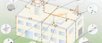
A thunderstorm, as a natural phenomenon, is accompanied by lightning that strikes mainly tall objects. The high energy inherent in lightning discharges, under unfortunate circumstances, can lead to:
- destruction of elements of an architectural object;
- failure of electronic equipment;
- the occurrence of a fire;
- death of people and farm animals.
The only way to prevent this is a lightning protection device. The purpose of lightning protection is to forcefully drain the atmospheric discharge current directly to the ground along a ground loop specially created for this purpose, which avoids its direct impact on building structures, animals and people. Lightning protection of a building is performed as a separate engineering system. The serviceability of the lightning protection system is confirmed by regular checks.
Who conducts the inspection?
Issuing a conclusion on the compliance of the lightning protection system of industrial buildings with the requirements of the standards is a technically complex procedure that can only be performed by specialized organizations.
The necessary conditions for issuing a lightning protection inspection protocol include the following provisions:
- the inspection organization has a testing laboratory, which is additionally confirmed by a registration certificate;
- specialized education of laboratory staff;
- application when testing measuring instruments with valid verification.
A laboratory is an independent structural unit of an organization with an approved staffing table.
Installation companies usually subcontract a certification laboratory.
The cost of checking the lightning protection system at MZK-Electro
| Building type | Cost, rub. |
| Private houses | From 5 000,00 |
| Administrative buildings | From 10 000,00 |
| Industrial building | From 15 000,00 |
Typically, checking a lightning protection system includes:
- visual inspection of the integrity of lightning rods and down conductors, the reliability of their connection and fastening to the masts;
- identification of elements of lightning protection devices that require replacement or repair due to a violation of their mechanical strength;
- determination of the degree of destruction by corrosion of individual elements of lightning protection devices;
- checking the reliability of electrical connections between live parts of all elements of lightning protection devices;
- checking the compliance of lightning protection devices with the intended purpose of the objects;
- measuring the resistance value to the spreading of pulsed current using the “ammeter-voltmeter” method using a specialized measuring complex.
The results of inspections are formalized in acts, entered into passports and a logbook for recording the condition of lightning protection devices. Based on the data obtained, a repair plan and elimination of defects in lightning protection devices discovered during inspections and checks is drawn up.
Types of checks
Inspections of lightning protection elements, regardless of their execution, are divided into control, extraordinary, and one-time.
- The main distinguishing features of lightning protection control checks are their implementation in a full cycle with measurement of characteristics and according to a pre-agreed plan.
- Extraordinary inspections are usually carried out by visual inspection after natural disasters, as well as particularly severe thunderstorms. Resistance measurements are not performed.
- One-time lightning protection checks of various depths are performed after:
- completion of system installation;
- making any changes to the system, incl. repair;
- damage to the protected object.
Installation research process: basic methodology
We have clarified that the fundamental purpose of revising a lightning protection device is precisely to clarify the compliance of the constructed structure with the standards and PUE.
At the first stage, we must familiarize ourselves with technical documents and acts. They should describe all factors observed during the initial installation of the lightning arrester mechanism. Also, the acts usually indicate when lightning protection devices are checked and inspected from the moment of their commissioning.
The second stage is to inspect all parts visually. With this operation you can verify the integrity of the components. It is ideal to carry out all checks by tapping the conductors; you can forcefully check the places where there are welded or fastening connections. At the third stage, you will have to analyze each individual lightning rod. For this it is better to use a special device
Please note that the resistance obtained during the study should not exceed five times the value assigned at the time the device was put into operation. During the inspection process, be sure to measure the contact connections and characterize the insulation resistance. In fact, the entire project can be characterized as a multi-stage methodology.
Test procedure
The lightning protection system of architectural structures, especially industrial facilities, is often highly complex. This requires dividing the process of monitoring its current state into a number of stages, which are performed using a variety of visual and instrumental testing methods.
Stages
Typically, in the process of certification of a lightning protection system, the following stages are distinguished:
- obtaining the necessary initial data from existing design documentation;
- monitoring the actual compliance of the system with project documentation;
- visual inspection of system devices. The purpose of the inspection is to control the integrity of welded joints (with tapping), the absence of corrosion, and the condition of contacts;
- measurement of grounding resistance.
In situations where several lightning rods are used to protect an object, the test is carried out separately for each of them.
Normalized parameters
Lightning protection of industrial facilities (architectural structures plus communications) is checked for compliance with the requirements of departmental instructions RD 34.21.122-87 and SO 153-34.21.122-2003 of the Ministry of Energy. The provisions of PTEEP (Chapter 2.8) standardize the principles of protecting electrical devices from the effects of voltage surges.
The standards fix the maximum transition resistance of lightning protection contacts at 0.03 Ohm. The maximum resistance of the grounding device is set to 10 ohms.
When installing electrical installations, they additionally monitor compliance with regulatory requirements for the distance to the object, the size of the recess, as well as the design of the elements of the grounding device in places with different soil resistance. Separately, check the minimum distance of the grounding conductor from metal communications.
Measurement methods
During instrumental monitoring of lightning protection, the following types of resistance measurements are performed:
- checking the contact resistance of circuits at the junction of individual components;
- determination of the resistance of protection grounding conductors.
The reliability of the results is increased by testing grounding devices at the peak of the dry season or at the deepest freezing of the soil.
During visual inspection of lightning protection, which is carried out during the day in clear weather, the degree of corrosion and other damage to the surface and structure of system components is checked. If, for example, during an inspection of lightning rods, those with more than a quarter of the surface area damaged are found, they must be replaced.
Documentation (acts, protocols)
Based on the results of checking any specific parameter or their complex, a protocol is drawn up. In relation to the lightning protection system, the following protocols are distinguished:
- visual inspection of the technical condition of the system and/or its individual components;
- contact resistance measurements;
- resistance measurements when testing the contour of grounding devices.
The protocol can be drawn up in relation to part of the system, and also contain the results of a full cycle of examinations without breaking it down into separate components. In measurement protocols, which are drawn up in accordance with GOST R 50571.16-99 (harmonized with IEC 60364-6-61-86):
- note the measurement conditions;
- give a description of the object;
- describe the type of testing equipment;
- record identified violations;
- note the data of the persons who performed the tests.
The document must contain all the information necessary to substantiate the conclusion based on the test results in the “pass-fail” form in relation to normal technical operation.
The protocols are supplemented with a lightning protection organization diagram, copies of verification certificates, certificates of certification of laboratory employees and other necessary documents. A sample protocol form is shown in Figure 1.
Figure 1. Approximate form of a protocol for measuring parameters of a lightning protection system
The act differs from the protocol in that it is always drawn up collectively. The Commission, according to established tradition, includes an odd number (at least three) members. The act is additionally approved by the customer’s manager or one of his deputies.
In relation to lightning protection, an inspection report and an acceptance certificate are drawn up.
Acts of inspection are de facto carried out in the form of a protocol.
Acceptance reports include measurement protocols. Often such an act is a general document, the content of which is completely included in the appendices.
The procedure for conducting inspections of lightning protection devices
The volume and content of inspection activities may change, as they depend on the implementation of the current list of preventive works or on orders issued in connection with unscheduled inspections. If the diagnosis of the lightning protection system corresponds to the most complete work program, then the following is performed:
- Compare the data available in the design documentation with real indicators.
- They check the compliance of protective zones and structures with the requirements of regulatory documents.
- Inspect protective devices, down conductors, and connecting contacts to check their integrity, the absence of traces of rust, and the quality of installation connections.
- Welds are checked for integrity and strength by applying mechanical forces (tapping with a hammer).
- Measure the resistance of bolted joints.
Measurements of the grounding resistance coefficient of lightning rods are carried out separately for each device. The final indicator should differ no more than five times from the data obtained during the introductory tests. If the grounding conductor performs a related task (working grounding conductor of the building and lightning protection system), there is no need for resistance measurements.
To obtain the most accurate results, planned and start-up testing work is carried out during the lowest level of moisture in the soil adjacent to the building. In regions belonging to permafrost zones, measurements are carried out during the period of maximum freezing of the ground.
Note! When testing the system, the level of atmospheric pressure is taken into account. This parameter is secondary, but is included in the final protocol.
Useful tips Connection diagrams Principles of operation of devices Main concepts Meters from Energomer Precautions Incandescent lamps Video instructions for the master Testing with a multimeter
Necessary measuring equipment and instruments
The quality of the lightning rod installation is checked using appropriate measuring equipment. Both automated and manual meters are available. Manual equipment is considered obsolete and is gradually being phased out.
The most widely used among automated lightning protection testing devices is the Polish-made MRU-101. Meter MRU-101:
- Performs ground resistance measurements;
- determines the resistivity of the geosubstrate;
- measures the spreading current;
- selects a range with the necessary settings after pressing the START key;
- stores several hundred test results.
The strength of the MRU-101, the interface of which is shown in Figure 2, is constant monitoring of the noise level and measurement conditions with a complete stop of the process when gross errors are detected. In addition, when the device determines that unreliable readings may be obtained, it generates a warning message.
Figure 2. Controls, probe connectors and indicator of the MRU-101 meter
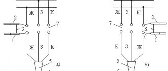
To carry out lightning protection tests, a three-pole circuit is most often used, the structure of which is shown in Figure 3 with the working inputs H, S, E of the meter being connected to three different measuring probes driven into the ground in the area of the grounding loop electrodes. The distance between the probes is chosen to be at least 20 m.
Figure 3. Three- and four-pole diagrams for connecting the MRU-101 device to measuring probes
A four-pole circuit is less commonly used. Its difference from the three-pole one is the connection of the ES input with an additional wire to the same electrode that is connected to the E input (see Figure 3).
MRU-101 also allows you to measure the spreading current using a non-contact method. To do this, connect the measuring clamps, which are included in the delivery kit, to the fifth input as shown in Figure 4. Measurements require preliminary calibration of the clamps, performed automatically.
Figure 4. Connection diagram of measuring clamps to the MRU-101 device
The procedure and frequency of measurements
When performing extraordinary tests, the main attention is required to measure the resistance of the grounding loop of the protective system. This indicator entirely determines the speed at which the electric discharge will go into the ground. Therefore, during research, the main parameters of the circuit are checked and compared with established standards.
In accordance with the rules and regulations, visual inspections of lightning protection are carried out at least once every 6 months, and a full inspection is carried out at least once every 12 years and is accompanied by excavation of soil in potentially dangerous places.
Electrical laboratory services
Despite the relatively low probability of being used for its “direct” purpose at most facilities, the lightning protection system is included in the list of special responsibility, since not only the integrity of expensive equipment or building structures, but also human lives, as a rule, depend on its performance. Therefore, it is better to entrust the creation and maintenance of such systems to professionals - a licensed electrical laboratory with qualified personnel using certified electrical measuring instruments.
One of these professional organizations is the electrical engineering laboratory (ETL) "Mega.ru", which provides a wide range of services to organizations and individuals in Moscow, the Moscow region, as well as surrounding areas.