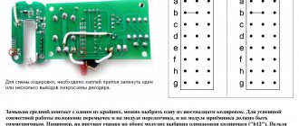
During a long working process, the windings of any electric motor overheat and the insulating coating deteriorates. Such situations often lead to interturn short circuits, burnout of poles and other negative consequences that require urgent and expensive repairs. A thermal relay for the electric motor, installed in the power circuit and providing reliable protection against overheating, helps to avoid this.
Well, now let's move on to calculating the correct setting of the thermal relay!
Let's take the Grundfos pump as an example.
We take the input data for the calculation from the plate on the electric motor.
f = 60 Hz
U = 220-277 ∆ / 380-480 Y V
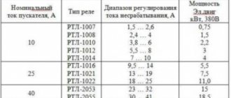
Formula for calculating the rated current (full load current) In = 5.70 - 5.00 / 3.30 - 2.90 A
Let's imagine that:
- Ua = actual voltage 254 ∆ / 440 Y V (actual voltage)
- Umin = 220 ∆ / 380 Y V (minimum values in the voltage range)
- Umax = 277 ∆ / 480 YV (Maximum values in the voltage range)
The voltage ratio is determined by the following equations:
- For the connection diagram, triangle UΔ = (UA - Umin) / (Umax - Umin), which in this case: UΔ = (254 - 220) / (227 - 220) = 0.6
- For the star connection diagram UY = (UA - Umin) / (Umax - Umin), which in this case: UY = (440-380) / (480-380) = 0.6
And so we get that UΔ = UY
Design of thermal relays
Thermal relays of all types have a similar device. The most important element of any of them is the sensitive bimetallic strip.
The operating current value is influenced by the temperature of the environment in which the relay operates. An increase in temperature reduces the response time.
To minimize this influence, device developers choose the highest possible bimetal temperature. For the same purpose, some relays are equipped with an additional compensation plate.
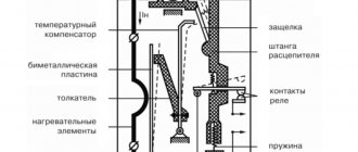
The device consists of a housing, a nichrome heater, a bimetallic plate, a latch, a screw, a lever, a moving contact and a return button (+)
If nichrome heaters are included in the relay design, they are connected in a parallel, series or parallel-series circuit with a plate.
The current value in the bimetal is regulated using shunts. All parts are built into the body. The U-shaped bimetallic element is fixed on the axis.
A coil spring rests against one end of the plate. The other end is based on a balanced insulating block. It rotates around an axis and is a support for a contact bridge equipped with silver contacts.
To coordinate the setting current, the bimetallic plate is connected at its left end to its mechanism. The adjustment occurs due to the influence on the primary deformation of the plate.
If the magnitude of the overload currents becomes equal to or greater than the settings, the insulating block rotates under the influence of the plate. When it is tipped over, the device's normally closed contact is switched off.
TRT thermal relay in section. Here the main elements are: housing (1), setting mechanism (2), button (3), axis (4), silver contacts (5), contact bridge (6), insulating block (7), spring (8), plate bimetallic (9), axle (10)
The relay automatically returns to its original position. The self-return process takes no more than 3 minutes from the moment the protection is turned on. A manual reset is also possible; a special Reset key is provided for this.
When using it, the device takes its original position in 1 minute. To activate the button, turn it counterclockwise until it rises above the body. The installation current is usually indicated on the panel.
Now let's calculate the actual full load current of our pump (I)
- Current for values with a delta connection diagram: 5.70 + (5.00 - 5.70) × 0.6 = 5.28 = 5.30 A
- Current for values with a star connection diagram: 3.30 + (2.90 - 3.30) × 0.6 = 3.06 = 3.10 A
The main rule is that the motor thermal overload relay is always set to the rated current indicated on the nameplate.
However, if motors are designed with a performance factor in mind, which is then stated on the nameplate, e.g. 1.15, the specified current for an overload relay can be increased by 15% over the full load current or the ampere service factor, which is usually indicated on the nameplate.
CONCLUSION: in our case, the motor is connected according to the star circuit = 440 V 60 Hz, the overload relay should be set to 3.1 A.
The thermal relay is activated. Overload or what could it be?
Hi all.
Glad to see you on the pages of my site. Today I decided to add another section to the blog, in which I will write about cases in my practice. Events of old days. I worked the night shift, and there was very little left until the end of my shift, about one hour. I receive a request on my phone that the pump on the ground floor in the refining shop does not turn on. I take a tool, a clamp meter, and go to the call. Arriving at the site where the cabinets with PZA are located, I needed the equipment. I opened the cabinet, and when inspecting the start-up protection equipment, I discovered that the TRN25 thermal relay had tripped. The relay model is a bit old, but they work well and are widely used at our plant.
I didn’t have time to figure out what was what, so I quickly checked the electric motor with a pointer for a breakdown in the housing, returned the relay, and started the engine. I immediately measure the load - it shows 10 Amps. The electric motor on the pump is 7.5 kW, which means its rating should be within 14-15 Amperes. By the way, in this article, I wrote how to calculate the rated current of an electric motor, if you are interested, read it. The thermal relay is rated at 16 Amps, in theory everything should work perfectly.
This pump does not work all the time. It is turned on for a few minutes every 2-3 hours. I decided to check with the person who turns it on. Under what conditions did the protection work - when the pump arrived, it no longer turned on, or it was knocked out already in working condition.
According to Sergei, that’s the name of the man who works on the line, the pump was already knocked out when he came to turn it on. This means that the thermal relay worked during the previous switch-on. I thought that Sergei simply turned off the pump incorrectly. You must first turn off the pump and then close the taps. But he probably did the opposite.
During the shift change, I told the shiftman everything and went on two days off.
Two days later, I took up my shift again, and the person I was replacing told me that the pump had been on and off for two days, and then worked normally. I immediately thought that I needed to look for the reason for these stops.
Having started my shift, I immediately call Sergei and tell him to call me when he turns on the pump. And now, I’m already standing with a current clamp near the PZA. We turned on the pump, the current again shows 10 Amps. It worked for about 5 minutes and was turned off.
I immediately disassemble the electrical circuit for turning on the pump, and begin checking all the devices for the presence of heating. There was slight heating on one phase of the thermal relay. I completely replaced one bimetallic insert and retightened all the bolted connections.
But when I opened the electromagnetic starter, everything immediately became clear to me. The starter there was PME-211, and the contacts on it were slightly burnt. I decided to check whether the contacts close when the starter retracts. I apply the pointer to the upper and lower contacts, and forcefully retract the starter.
When checking this, I found that the contacts close every other time. With such work, it turns out that only two phases were supplied to the electric motor, the current was large, and this triggered the thermal relay.
I checked the starter. After this there were no more problems with the pump.
This is the story I had during my shift. I hope you liked the article. I gave a real example under what circumstances a thermal relay can operate. I would be glad if you share this article with your friends on social networks. Also subscribe to my site updates. Bye.
Sincerely, Alexander!
Time relay (10 preset functions) RT-10 EKF PROxima, rt-10
Multifunctional time relay RT-10 EKF PROxima is an electronic switching device with adjustable operating modes and adjustable time settings. The relay is designed to turn on or off the load according to specified time values and operating modes. Switching between time ranges and operating modes is done using rotary controls located on the front surface of the relay. The relay is used in industrial and household automation systems: in ventilation, heating, lighting systems. Application category – AC-15 (control of electromagnets with power over 72 W).
Passport RT-10
| Status: | Regular |
| Nom. current, A | 8 |
| Quantity output. changeover contacts without delay | 1 |
| Nom. control circuit supply voltage Us AC 60 Hz, V | 230…230 |
| Nom. control circuit supply voltage Us constant. current DC, V | 24…24 |
| Time range, s | 0.1…8640000 |
| Control voltage type | AC/DC (variable/constant) |
| Variable delayed/non-delayed outputs | No |
| A replacement unit will complement. contacts | No |
| Quantity output. changeover contacts with delay | 0 |
| Quantity output. normally open contacts with delay | 0 |
| Pulse device | No |
| Suitable for DIN rail mounting (with ?-profile) | Yes |
| Quantity output. normally open contacts without delay | 0 |
| Quantity output. normally closed contacts without delay | 0 |
| Service life, years | 10 |
| Nom. control circuit supply voltage Us AC 50 Hz, V | 230…230 |
| Electrical connection type | Screw connection |
| Quantity output. normally closed contacts with delay | 0 |
| Switch off delay function | Yes |
| Changeover contact for switching off | Yes |
| Only suitable for remote control | No |
| Height, mm | 91,4 |
| Depth, mm | 49 |
| Suitable for front mounting | Yes |
| Warranty period, years | 7 |
| With plug socket/socket | No |
| Remote control possible | Yes |
| Instantaneous, delayed, unchangeable function | No |
| Width, mm | 18,5 |
| Instant impulse function | No |
| Time function, switch on with delay, changeable | Yes |
| Time function, impulse activation. Variable turn-on delay | No |
| With semiconductor output | No |
| Delay function | Yes |
| Change-over contact for switching on | Yes |
| Star-Delta connection | No |
| Series | PROxima |
Operating principle of the device
Performing a protective function, the circuit breaker disconnects the power supply circuits. A thermal relay differs from it in that when the load is exceeded, it simply issues a control signal. With such protection, small currents are switched in one control circuit.
In the circuit in front of the thermal relay there is a magnetic starter. When the circuits are opened in an emergency, there is no need to duplicate the operation of the contactor. Consequently, no material is consumed for the manufacture of power contact groups.
The most popular are devices equipped with bimetallic plates. The plate itself consists of two similar elements.
One of them has a significant temperature coefficient, while the other has a slightly smaller one. These two components fit tightly together.
Since the components of a bimetallic strip are made of a pair of dissimilar metals having unequal expansion coefficients, heating causes it to bend and interact with the contacts
Such rigid fastening is ensured by welding or hot rolling. Due to the fact that the plate is fixed motionless, when heated, it bends towards the element with a lower temperature coefficient. This principle is taken as the basis when creating thermal relays.
In their production, chromium-nickel steel and non-magnetic steel are used, which have a high temperature coefficient. Invar, a compound of nickel and iron, is used as a material with a low value of this parameter.
A thermal relay operates according to this scheme. The loose end of the bimetallic plate, when it bends, affects the contacts of the thermal relay (+)
The bimetal plate is heated by load currents. They most often flow through a special heater. There is also combined heating, in which, in addition to the heat given off by the heater, the bimetal is also heated by the current passing through it.