Control devices and time relays
The equipment we offer is designed to work as part of a variety of monitoring and dispatching systems. Control devices carry out the process of working with m2m systems: they control microclimate systems, implement cyclic switching of electrical networks at unattended facilities.
- time delay relay;
- data collection devices;
- controllers BRKV (rotation unit for air conditioning and ventilation);
- sensors;
- and other auxiliary elements.
In addition to the indicated control and automation devices, auxiliary elements for them are available. For example, a bracket for a transmitter. All control devices and time relays are made of high-strength materials that are not subject to fire and corrosive influences.
RVs are used where there is a need:
- execute commands with a certain selectivity, i.e. selectivity;
- turn on and off the load at a certain time, i.e. use RV as a timer;
- perform a series of sequential (programmed) actions or commands spaced over time;
- execute a command for a specified period of time.
Thus, the functions of the time relay are extremely diverse, and the time delays that can be used range from tenths of a second to tens of hours or days. The upper limit of shutter speed is limited only by the imagination of the author of the device.
Selectivity is used most often in relay protection devices. For example, there is a power line fed by a switch at the head and sectioned by a switch in the middle. The protection is mounted on the head switch. A short circuit (short circuit) occurs on it. How does line protection behave? Since the protection itself cannot determine the location of the short circuit, it is made selective using a time relay. With the first time delay, say 0.5 seconds, the sectional switch is turned off. If the short circuit is not eliminated, then it is closer to the power switch, then with a second delay, say, 1.0 second, the main circuit breaker is turned off. KZ has been eliminated.
The load switch function is widely used to control, say, object lighting. They turn on and off at a certain time. The program action function is widely used in industry when it is necessary to perform a series of actions, for example:
- turn on the boiler furnace ventilation at time X for Y minutes;
- allow fuel supply to the burners during X + Y.
This is already program work of the radio and work for a given period of time.
Types of time relays
Types of time relays by general design
So, we found out that switching contacts in a time relay occurs with a certain delay after the supply or control voltage is applied or removed. But before we move on to the consideration of the devices themselves that ensure operation according to a given algorithm, we note that time relays, according to their layout or general design, can be divided into several types.
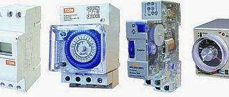
- Monoblock time relays . These are completely independent devices with their own housing, built-in power supply or a device for connecting power, with an output to which you can connect third-party household or other equipment. Such a relay can be installed in almost any place as needed, and the device (system) that requires such time control can be connected to it. A classic example would be a time relay, with which those who have been involved in photo printing are very familiar.
Such a time relay made it possible to very accurately observe the selected exposure of photographic paper when printing photographs.
Devices of wider use include modern time relays (timers) that stop at a socket and have a socket for connecting a power plug to the load. The simplest example of use is that you can program in the evening so that water is boiled in the electric kettle before the owners get up in the morning.
Time relays (or timers) that are plugged into an outlet and themselves become a “controlled outlet” for the electrical appliance connected to them. As you can see, they can be electromechanical and electronic.
- Built-in time relays . They do not have their own housing, are one of the components of an electrical device (or are intended for such installation), and, as a rule, are not used autonomously. A classic example of such a time relay is a mechanical or electronic timer that controls the operating modes of a washing machine, microwave, electric oven, etc.
Built-in time relay, as a separate unit of the general device of a large household appliance.
Such relays can be electromechanical, having a block design. Another option is an electronic type relay assembled on a printed circuit board, which is connected to the general circuit of an electrical device.
Electronic time relay, made in the form of a mounting assembly on a printed circuit board
- Modular time relays . As is clear from the name, such devices have standardized dimensions and are intended for installation on the DIN rail of the distribution board. There, in the switchboard, a stationary connection is made to the power source and the load, the operation of which they will control. For example, in this way you can connect lighting systems that will operate according to a certain time algorithm, powerful heating devices, say, so that their main operation occurs during the hours of the discounted tariff, ventilation units to ensure a given ventilation frequency, etc. They can also be used with other large household appliances, if they do not have their own built-in timer in their design.
Modular time relays are available for sale in a wide variety of models of varying degrees of complexity and functional equipment
. Despite the uniformity of size, modular time relays can differ significantly in the range of capabilities, number of channels and programmable intervals. Depending on the degree of complexity and, partly, on the permissible power of the equipment connected to them, such relays can occupy one, two, three or even more module spaces on the DIN rail of the distribution board.
Such an electronic time relay with the ability to customize the daily cycle of operation will occupy three module spaces on the DIN rail
Convenient - such devices take up very little space, are not in plain sight, and are inaccessible to children. Many allow you to set a daily, weekly, monthly or even annual operating algorithm, that is, they do not require frequent intervention in management. But if there is a need to make adjustments, then the convenient location of the time relay on the rail, with all the controls located on the front panel, will allow this to be done without any difficulty.
Types of time relays according to operating principle
Now it’s worth figuring out what mechanisms provide the required time interval. According to this criterion, time relays can be divided into several types - these are electromagnetic devices, devices with a pneumatic or hydraulic retarder, motor ones, relays with a mechanical clock mechanism and electronic ones.
Prices for CRM time relays
CRM time relay
Let's look at them briefly in the order listed.
Electromagnetic time relays
They are usually used in start-up and stop stages of powerful equipment - they allow the start-up of individual components (mechanisms) to be spaced out somewhat in time in order to avoid sudden surges in the load on the power line.
The operating principle of the response delay unit is as follows. Structurally, the relay is an electromagnetic coil. The movement of the armature attracted to the core of the coil is transmitted to the contact closing/opening mechanism. But a sleeve (most often copper) is put on a common core with the coil, which becomes an additional short-circuited circuit.
The principle of an electromagnetic time relay
When supply voltage is applied to the coil, an EMF is induced in this additional “winding”, creating a current in such a direction that it is “opposite” to the current in the main coil. That is, it kind of “quenches” the rate of increase in the intensity of the electromagnetic field necessary to attract the relay armature. And as a result, the contact group does not operate instantly when the power is turned on, but with a delay, the duration of which can be adjusted by the level of compression of the armature spring. The delay range is typically between 0.07 and 0.15 seconds.
A “classic” example of an electromagnetic time relay is the REV 812 model used in power supply circuits of powerful equipment.
When the power is turned off, the opposite picture occurs - due to the presence of an additional winding-sleeve, a kind of “inertia” effect is observed, and the opening of the contacts also occurs with a delay. It can range from 0.5 to 1.5÷2 seconds.
Pneumatic or hydraulic time relays.
It is unlikely that you will have to deal with them in everyday conditions - they, too, were installed only on powerful processing equipment. But it will still be interesting to get acquainted with the deceleration mechanism, because it has a rather original design.
Time relay RVP 72-3221 with pneumatic retarder
Structurally, such relays necessarily include a chamber with a diaphragm, into which a movable unit (block) rests, causing switching of contacts. When the voltage is removed from the coil winding, the block is released and begins to move under the action of the spring. But the movement of the block is slowed down by the diaphragm until the air leaves the pneumatic chamber. And the speed of air release depends on the cross-section of the hole, which, in turn, is regulated by a special needle.
Adjustments to the response delay interval can be carried out over a fairly wide range and with a high degree of accuracy.
In addition to pneumatic ones, there are also hydraulic retarders, in which liquid (for example, transformer oil) is passed through an adjustable hole between the chambers. But the operating principle does not change.
Motor time relays
Such devices also seem to be becoming relics of the past, although they can still be found on older types of industrial equipment.
Operating principle of motor timing relay
A characteristic feature of such devices is the presence, in addition to the coil inherent in most relays, also of its own electric drive. When the power is turned on, it is supplied to both the coil and the electric motor, from which rotation is transmitted through a gear system to the impellers. On these wheels (which have a time graduation) there are special protrusions that at a certain moment will cause the contacts of the coil power circuit to close or open. Well, turning on or off the power on the coil winding, in turn, provides the necessary switching of the power lines connected to the time relay.
Prices for Feron time relays
Feron time relay
The response time is set by the initial position of the impeller. By the way, one relay can have several such wheels, which makes it possible to organize rather complex algorithms for controlling the connected load.
Motor time relay VS-33
Time relay with anchor (clock) mechanism
The simplest and most obvious example of an analogue of such time relays is an ordinary table clock with an alarm clock, powered by a battery. The response time is set by a separate special arrow. And when the hour hand aligns with it, the contact will close and power will be supplied to the sound signal generator.
Of course, the time relays themselves are somewhat more complicated, and the load connected to them is much more powerful than a miniature beeper. But the principle of operation is very similar. The timekeeping mechanism is almost completely analogous to a conventional watch. In some older relays, even the spring is wound manually, as needed. In others, the winding is carried out automatically when the power is turned on due to the movement of the electromagnetic armature.
Time relay with clock mechanism RV 235 UHL4. They have been discontinued for a long time, but continue to serve faithfully for some owners.
Relays with a clock mechanism are available for sale in a wide variety. Models with a dial divided into 24 hours are very popular among users, and each hour is usually divided into four segments of 15 minutes. Each such minimum interval corresponds to a movable sector (pin, lever, depending on the model).
When the relay is connected to the network, the dial begins to rotate at an angular speed of one revolution per day. The dial displays the current astronomical time. Well, then it’s easy to program the relay operation algorithm by pressing (tilting or otherwise moving) the movable sectors corresponding to those periods of time when the power to the load should be turned on.
Programming the operation algorithm of such a time relay is simple and intuitive.
Such time relays are available in a modular or monoblock design, that is, they are either installed in a distribution cabinet or directly connected to an outlet. Their low cost and ease of operation have earned them wide popularity. The accuracy of setting the range and relay operation, of course, cannot be called high (minimum gradation of 15 minutes), but for most household appliances this is quite enough.
Well, if more precise settings are required, down to the second gradation, then it is best to immediately purchase an electronic time relay.
Learn how to wire an outlet and see step-by-step examples of how to properly connect a wire to an outlet.
Electronic time relays
Electronic time relays are currently increasingly replacing their electromechanical “brothers”. This is understandable - what attracts is the high accuracy of operation, the possibility of programming for a long period: for a week, a month or even more, taking into account the alternation of weekends and holidays, season changes, and other factors influencing the expected operating mode of electrical appliances connected to the relay.
Electronic time relay with a rich set of programming capabilities for the control algorithm of connected electrical devices or systems
This category also has its own division for response timing technology. We will not delve into the topic - this question is rather of interest to electronics specialists.
We can only briefly explain that the simplest electronic relays count time using RC circuits (resistor + capacitor). The charging time of the capacitor depends on the value of the capacitor itself and the resistor connected to it in the circuit. That is, it is easy to calculate, and by smoothly changing the values of circuit elements or changing chains (in some relays there are several of them), you can set the desired response delay interval.
More complex time relays are equipped with special microcircuits or a cascade of semiconductor devices that provide the necessary time delay. Well, the most modern ones today have microprocessor units and quartz reference frequency oscillators. So the time counting in them occurs with maximum accuracy, and the non-volatile memory allows programming of the operating algorithm.
Electronic time relay of modular design with analog adjustment of operating parameters. Relatively inexpensive and very often - quite enough.
The range of electronic time relays is very wide. It is quite possible to purchase a relatively inexpensive model with analog parameter settings and providing the simplest operations of turning on and off the power line with the required delay or according to a certain algorithm. Often, to implement the intended automation of a particular process, such a device is quite sufficient. More advanced time relays are equipped with digital liquid crystal displays and a push-button (touch) control system with parameter setting accuracy literally down to a fraction of a second. Convenient, but the cost certainly increases proportionally.
You can also add that electronic time relays can be produced in any of the designs - as separate monoblock devices (for example, again, the “socket with timer” option), in the form of boards or blocks for installation in equipment, or in a modular layout for placement on DIN rail.
Video: Example of using an electronic time relay KEMOT URZ2001-1
* * * * * * *
By the way, there is a lot of confusion about what is more correct to call such devices - time relays or timers. Arguments are given that the operation of the relay is linked to astronomical time, and the timer only counts down a given interval. Or vice versa, that the relay should only provide a delay on and off, and all that concerns programming capabilities (setting the operating algorithm) are timers. Thus, the statements directly contradict each other.
According to the author of this article, the “border” between these types of devices, if there is one, is very arbitrary. And fooling yourself with the subtleties of terminology hardly makes sense in this case. The main thing is to understand and be able to formulate why you need a control device and what functions it should have. And you can rest assured that a competent sales consultant will understand you perfectly and offer the optimal model. And by the way, her passport may indicate both a timer and a time relay. And often – both terms at once, separated by a dash or in parentheses.
Room thermostat and energy saving
To get a more functional option, let’s add here a device for monitoring the air temperature in the room - a room thermostat.
It doesn’t matter to him what the temperature of the boiler water will be; he reacts precisely to the comfortable air temperature in your home. By analogy with the previous elements, mount it in the gap, in front of the working thermostat. The second simplest scheme is ready
The second simplest scheme is ready
By analogy with the previous elements, mount it in the gap, in front of the working thermostat. The second simplest scheme is ready.
But people always strive for more, and in addition to the comfort of electric heating, they always want to save money. Still, with rare exceptions, electric heating is not exactly a cheap thing in our realities.
How to do this by improving the above connection diagram? There is a night rate for this business.
To take full advantage of it, we need a time relay.
It will start electric heating only during a specified period of the day. Place it in the circuit in front of the room thermostat.
However, pay attention to one nuance. If there is such a device in the circuit, a minimum air temperature thermostat must be mounted parallel to it. During the day, in your absence, the temperature outside may drop sharply
We left at -5C, arrived in the evening - minus 25C outside. Accordingly, your home will become significantly colder
During the day, in your absence, the temperature outside can drop sharply. We left at -5C, arrived in the evening - minus 25C outside. Accordingly, your home will become significantly colder.
It will start heating as soon as the temperature in the house drops below the minimum threshold. As a result, it will prevent the house from cooling down and the system from defrosting.
To visually observe whether the sensors are turned on or off at the moment, you can connect a signal light to a common point in front of the microswitches and display it in a visible place.
This is especially useful when the control panel and the boiler itself are located in the basement of the house or in a neighboring outbuilding.
Most factory electric heating boilers are built precisely on such basic control schemes. There is one supply line (phase) that supplies a signal to the coil of the device with power elements, and all additional equipment, sensors and switches are “hung” on this very line, performing protective and monitoring functions.
As you can see, there is nothing complicated or intricate here.
https://youtube.com/watch?v=fw9BUOGXT4Y%3F
Specifications
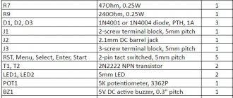
| Parameter | Meaning |
| Rated operating voltage | 220V |
| Mains frequency | 50/60Hz |
| Remains operational when the supply voltage is within | 180V-250V |
| Relay power consumption | no more than 2VA |
| Permissible switching contact current, with active load | 16A |
| Permissible switching contact current, with reactive load | 8A |
| Minimum programming step | 1 minute |
| Maximum programming step | 168 hours |
| Number of on/off programs | 16 cycles |
| Mechanical wear resistance, on/off cycles | 10⁷ |
| Electrical durability, on/off cycles | 10⁵ |
| Programming data storage time when power is turned off | up to 150 hours |
| Accuracy of the watch during the day, at a temperature of +25°C | ≤1 second |
| Overall dimensions (HxWxD), mm | 86.5x36x65.5 |
| Operating temperature range, °C | -10°С~+40°С |
| Relative humidity | 35~85% |
DIN rail mounting (occupies two S-type modules), the size of a two-phase automatic machine. Operate indoors with artificial ventilation and heating control.
Technical characteristics of photo relay
The level of maximum operating load of a photo relay depends on which devices are connected to it. You need to know that the maximum load of the device is from 1000 to 2300 W, the rated operating voltage is 220 V, and the photorelay threshold limits are 2-2000 lux (lux).
In order for the photo relay you purchased to serve you for a long time and successfully, you need to know from the very beginning what criteria to focus on when purchasing this device and its auxiliary elements. The device can work for a long period of time without creating any problems, or it can break down every week.
We will try to figure out whether it is possible to avoid problems during installation and operation and how to do this. I would like to note that the color of the wires for connecting the relay is different for different manufacturers, so be sure to read the instructions, which show the wiring diagram for the photo relay.
The most popular devices on the modern Russian market are economy class photo relays from manufacturers such as IEK, TDM, EKF, etc.
The photo relay FR-601 and FR-602 with a degree of protection IP44 is offered to us by IEK. Thanks to IP44 protection, the use of these devices is possible outdoors, because IP44 protects us from splashes falling in different directions. The limits within which the response threshold of these photo relays are located can range from 5 to 50 lx. Operating temperatures vary from -25 °C to +40 °C.
You need to know that at an illumination threshold of 5 lux, darkness sets in, while objects are still quite distinguishable. Therefore, in economic conditions, turning on street lighting at such a threshold of illumination does not always justify itself. Deep twilight corresponds to a threshold of 2 lux, when the onset of darkness occurs within 10 minutes.
Photo relay connection diagram
The photo relay automatically turns the lamp on when it gets dark outside, and, conversely, turns off the street lighting when it starts to get light outside. Thanks to this, not only does the service life of the lamps themselves increase, but also significant energy savings occur.
If we talk about the technical characteristics of the photo relay. then it should be noted that the power source is 220 V alternating voltage, and the switched circuit does not exceed 10 A. It should also be said about the working illumination, the level of which is set using the regulator located at the bottom of the relay, and this level can vary from 5 to 50 Lux.
If you want the photo relay to turn on the lamp in cloudy weather or during a slight eclipse, move the regulator to the “plus” side. By moving the regulator to the minus side, you can ensure that the relay operates only when it gets dark.
The photo relay is installed on the wall using a special bracket, which is attached with a screw to the relay itself. The bracket is included in the delivery kit, and when installing it, you should ensure that there is no interference that would prevent natural daylight from reaching the relay. There should also be no trees or other swinging objects in front of the photo relay.
How to connect a photo relay to lighting
Both on the product itself and on the packaging there is a diagram for connecting a photo relay for street lighting. The relay terminals are made of wires with multi-colored insulation to avoid the possibility of their incorrect connection during the connection process. You can guess the purpose of the wires if you know their color markings. In total, three wires come out of the photo relay:
- -black - phase;
- -green - zero;
- -red - commutating phase (to the lamp).
So how to connect a photo relay to lighting? Before you start connecting the photo relay, be sure to read its instructions. To connect the wires, a junction box is used, which is installed on the wall.
Load switching is carried out by interrupting the phase voltage and turning it on. A working “zero” connected to the green wire is necessary for power supply (the operating voltage of the photo relay is 230 V). This product has a rated load current of 10 A (2.2 kW).
If the switched load has a large power, then lighting control requires the use of a very powerful twilight switch. The FR-602 photo relay, whose load current is 20 A, deserves special attention over other devices in the model range of this manufacturer.
Similar materials on the site:
Diagram and principle of operation of an electromagnetic relay
Let's look at how this mechanism works from the inside.
- The inductor contains a movable steel armature.
- When voltage is applied to the coil, an electromagnetic field is formed around it, which attracts this armature to the coil.
- The frequency and timing of the voltage supply is electrically or mechanically controlled.
The structure of the device consists of three main elements:
- The receptive or primary is essentially the winding of the coil. Here the impulse is converted into electromagnetic force.
- Retarding or intermediate - a steel anchor with a return spring and contacts. Here the actuator is brought into working condition.
- Executive - in this part, the contact group has a direct impact on the power equipment.
Details and design
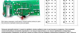
Fixed resistors can be of the type C1-4, C1-10, C1-14, C2-23, MYAT, RPM and similar ones of corresponding power. It is preferable to use a small-sized imported variable resistor R4. When using a domestic one, it should be taken into account that “our” variable resistors may have a deviation of more than 40% from the value indicated on the case, which will complicate the setup.
The author used an imported variable resistor with a resistance of 99.2 kOhm from the tuning unit to the channel from the Siesta TV-radio receiver. The axis of the resistor used is made of plastic; a polystyrene adjustment knob is attached to it.
The MYG10-471 disk varistor can be replaced with FNR-10K471, FNR-14K471, INR14D471, INR14D511. All chokes are small-sized industrial-made from computer devices.
If the resistance of the inductor winding L1 is less than 4 ohms, then a 2 W wirewound resistor must be connected in series with it; if it is more than 7...8 ohms, then the maximum power of the connected load may have to be reduced. Capacitors C1, C3 – C6 are high-voltage ceramic. Capacitor C8 is SMD, installed as close as possible to the power terminals DD1.
Oxide capacitors are imported analogs of K50-68. Capacitor C7 - film K73-17, K73-24 or an imported analogue.
The G2SBA60 diode bridge is designed for a current of 2A and a voltage of 600 V; it can be replaced with GBL06, RBV-406FI, G2SB60, or, for example, with four rectifier diodes 1N5406, KD226G, 1 N4006, KD243ZH, KD247D. These same diodes can replace diodes 1N4005, 1N4007. Instead of the FR107 diode, UF4007, FR157, FR207, FM207 are suitable. The Schottky diode SR360 can be replaced with SR306 or MUR460, UF5403, FR303G, SRP300J.
The 1SS176S diode can be replaced with any of the series 1 N914, 1 N4148, KD512, KD521, KD522.
The GZS12Z zener diode can be replaced with 1N4742A, BZV55C-12, TZMC-12 or the domestic 2S212Ts, KS212Ts. Instead of the BZV55C-18 zener diode, 1N4746A, TZMC-18 is suitable. The GZC5.1Z zener diode can be replaced with 1N4733A, BZV55C-5V1, TZMC-5V1.
You can try installing a domestic zener diode 2S151T1 in place of VD6. When installing domestic zener diodes in place of ZD1 and or VD5, you can get a non-functional design or damage powerful field-effect transistors due to overheating.
LEDs RL30-CB744D blue and RL30-DR344S red - with increased light output. Can be replaced with any similar ones, for example, from the KIPD21, KIPD40, KIPD66, L-1513 series.
One of these LEDs can replace AL307K. Instead of the PC817 optocoupler, any four-pin PC817, PS817S, PS2501-1, PC814, PC120, PC123SFH617A-2, LTV817 will do.
Transistor 2SA1266 can be replaced with any of the SS9015, BC557, KT3107, KT6112 series. Instead of KTS9013, any of BC547, SS9013, SS9014, 2SC1815, KT3102, KT645, KT6111 can work.
The main requirement for VT2 is low reverse collector current. Field-effect transistor VT1 operates without a heat sink at a load power of up to 30 W. With a load power of 16 W (incandescent lamp), the voltage drop on the open drain-source channel does not exceed 50 mV, and with a load of 60 W it does not exceed 200 mV. Instead of 2SK1118 you can install BUZ40B, IRFP450, IRF450, TSD2M450V, KP787A.
The best option to replace VT1 would be a modern field-effect transistor SPP20N60S5 or STW20NB50, MTW20N50E, SPW47N60C3. Instead of the field effect transistor SSS6N60A, SSS7N60B, SSS6N60A, SSP10N60B, P5NK60ZF, 2SK2562, P4NK60ZFP are suitable. When installing field-effect transistors, they must be protected from breakdown by static electricity.
Button SB1 is any small-sized button with freely open contacts without fixing the position with a plastic pusher. If the button has a metal clip, then it is connected to the “minus” VD1. This reduces the likelihood of a negative impact on DD1 from static discharge when the finger approaches the button pusher.
Instead of the KCD-2011 key switch, MR21, SWA206A, KCD1-101 are suitable. Instead of the TL431A chip, any one in the TO-92 package from LM431ACZ, AZ431, AN1431T will do.
Power relays - contactors
Since most of the relays discussed above are designed to switch loads with a power from hundreds of watts to ten kilowatts, additional high-power switching relays - contactors - are used to increase the switching power. With their help, you can switch a load of several hundred kilowatts, thereby expanding the capabilities of the previously discussed relays.
The use of various types of relays allows you to optimize the operation of many electrical appliances, protect against their accidental failure, and save your own life. On their basis, it is possible to create a large number of small automation systems, such as devices for maintaining an optimal microclimate, irrigation systems, automatic door opening, light switching on and off, and many others. Compact dimensions and standard dimensions of the case allow you to connect them directly to standard sockets or use ready-made electrical boxes for their installation, which significantly reduces the cost of automation in general.
Time relay connection diagrams
A variety of schemes are used to connect time relays. Their choice depends on what load is supposed to be switched with its help. The connection diagram for a time relay of the simplest type is selected so that it ensures stable operation of this device. The only drawback is that with their help it is possible to switch only one line with a limited load. Such consumers can be street light sources (lanterns) or lawn watering mechanisms.
Another circuit is used when it is necessary to control significant current loads. In this case, the contactor of the starter connected to the three-phase power supply circuit of an asynchronous motor, for example, is controlled by a time relay. Other options for installing and switching on the device are possible, depending on specific operating conditions.
Setting up analogue relays of electronic-mechanical type
Both industrial and domestic modules are in many cases equipped with electromechanical relays, which are adjusted using potentiometers. The front panel of such devices is equipped with one or more rods, which have a slot for a screwdriver blade. Around the rod, around the circumference, there is a scale installed or drawn with the markings of values that you need to focus on when setting the parameters. The slot into which the screwdriver is inserted has another function - it acts as a pointer. By turning the rod and setting it opposite certain values marked on the marking, the necessary adjustment to the desired parameter is achieved. Electronic-mechanical devices are actively used in circuits responsible for controlling ventilation systems, heating modules, and lighting devices.
Configuring electronic-mechanical analog relays
Industrial automation systems, as well as various household modules, are often equipped with electromechanical devices, the design of which allows for adjustment using potentiometers.
Electromechanical type of time counting device with parameter adjustment by potentiometers. There are various configurations of such devices, which makes it possible to use them in circuits of varying complexity.
On the front panel of the housing of such devices there is a potentiometer rod (or several rods) designed for rotation with a screwdriver blade. A marked scale of installation values is applied around the circumference of the rod(s).
The slot on the rod for the screwdriver blade is a kind of pointer that changes its position when the rod rotates. By placing this pointer opposite certain values of the marked scale, the desired parameter can be adjusted.
Multichannel device of electronic-mechanical type. Adjustment is easy and simple by rotating the potentiometers with a screwdriver. The front panel also has LED status indication
Devices of this type (for example, NTE8) are widely used in control circuits for ventilation systems, heating modules, and artificial lighting devices.
Current relay device
First, let's look at the principle of a current relay and its design. At the moment, there are electromagnetic, inductive and electronic relays.
We will disassemble the structure of the most common electromagnetic relays. Moreover, they provide the opportunity to most clearly understand their operating principle.
- Let's start with the basic elements of any current relay. It must have a magnetic circuit. Moreover, this magnetic circuit has a section with an air gap. There may be 1, 2 or more such gaps, depending on the design of the magnetic core. In our photo there are two such gaps.
- There is a coil on the stationary part of the magnetic circuit. And the moving part of the magnetic circuit is secured by a spring, which counteracts the connection of the two parts of the magnetic circuit.
- When voltage appears on the coil, an emf is induced in the magnetic circuit. Thanks to this, the moving and stationary parts of the magnetic circuit become like two magnets that want to connect. A spring prevents them from doing this.
- As the current in the coil increases, the emf will increase. Accordingly, the attraction between the moving and stationary sections of the magnetic circuit will increase. When a certain current value is reached, the EMF will be so great that it will overcome the resistance of the spring.
- The air gap between the two sections of the magnetic circuit will begin to decrease. But as the instructions and logic say, the smaller the air gap, the greater the attractive force becomes, and the faster the magnetic circuits connect. As a result, the switching process takes hundredths of a second.
It depends on the design, and can also be adjusted individually for each relay by tensioning or loosening the spring. This can be done with your own hands.
The most economical outdoor lighting control scheme
I have already devoted several blog topics to outdoor lighting control. Today I would like to present you with a slightly modified scheme that will allow you to save even more energy, and most importantly, turn the lighting on and off during hours when it is really dark.
I’ll say right away that I haven’t used this scheme yet and I hope for your help. So far this is only a semi-finished product =) Once a representative of the FIF came to me and told me about his products. I know the FIF company quite well and it’s not so easy to surprise me with anything.
I have already told you that I really like the astronomical time relay. According to the FIF, it can save up to 40% of electricity due to the fact that it turns off the lighting at night.
But, it is better to use a slightly more complex scheme - an astronomical relay + photo relay, which can save up to 60% of electricity.
They say that such a circuit is already used in outdoor lighting cabinets, however, I was unable to find a ready-made circuit, so I tried to develop my own circuit.
To implement the external lighting control circuit, I used a two-channel astronomical relay PCZ-527, a photo relay with an external sensor AZ-112, 2 circuit breakers and a contactor.
External lighting control circuit 1
With automatic switches, I think everything is clear. The input circuit breaker QF1 is designed for the entire load (can be single-phase), the additional QF2 is for protecting control circuits.
A contactor is required to switch the load (turn on/off lighting).
Photo relay AZ-112 and relay PCZ-527 control the contactor directly.
How does the scheme work?
We set one channel of the astronomical timer for the morning and evening, when the lighting should be turned on. The second channel is only for a day. Conventionally, the first channel works from 5.00 to 7.00 and from 17.00 to 24.00. Second channel from 7.00 to 17.00 (switch off at night). Depending on geographic coordinates, this time should constantly change.
Many people will have a question: why do we need a photo relay?
Imagine, the days are different. Sometimes it’s already evening time, and it’s still quite light outside. Why do we need to turn on the lights at this time? Or, conversely, it was a very cloudy day and it got dark outside before the sun went down, so we have to turn on the lights for our own safety. If there is a solar eclipse during the day, our circuit will turn on the lighting.
If necessary, manual control can be added to the circuit.
You can also offer a simpler and more economical option:
External lighting control circuit 2
Unlike the previous option, the outdoor lighting will not turn on earlier than set in the astronomical timer, and if it is light outside, it will not turn on either.
This circuit can also include a regular programmable timer, which is set to turn off at night. Those. The timer contacts are open from 1.00 to 5.00. The rest of the time the photo relay will work.
If you find a ready-made SHNO cabinet in which this idea is implemented (astro timer + photo relay or timer + photo relay), please send it to me.
Scheme with the possibility of local and remote control:
Circuit with local and remote control capabilities
MU - local government. Remote control - remote control. AU - automatic control.
I recommend reading:
Purpose and description of operation of additional inverter devices
Architectural lighting control in a park
How to turn on emergency lighting in case of fire?
Outdoor lighting control
Kinds
According to their design, time relays are divided into:
The monoblock is a completely independent device, with its own housing, built-in power supply and special sockets for connecting any equipment. Those involved in photo printing are well familiar with this type of relay.
Built-in relays are a simplified version of monoblock relays. They do not have their own housing and power supply, since they are needed in order to create more complex devices. They are used as additional elements and therefore they are placed in the same housing with other elements of the manufactured device. A classic example is a timer in a washing machine, microwave, oven, etc.
Modular (with control contact) - this type has standard dimensions and is installed on a DIN rail in the distribution panel.
In addition, time relays are also classified depending on the operating principle (how exactly the time interval is created):
- Time relay with clock mechanism. This type was the first to be manufactured and is still considered one of the most reliable, since its properties are not inferior to pneumatic devices. Their operation is practically independent of voltage power, how often it is applied, or temperature changes. In everyday life, this type of relay is found in mechanical alarm clocks, kitchen timers, and in some washing machines a mechanical program relay is also found.
- With electromagnetic retardation.
Used in circuits oriented to constant voltage. The delay is carried out by creating an auxiliary magnetic flux, regulated by changing the tension value of the return spring. The adjustable value is up to five seconds. A significant disadvantage of this type of relay is that the time delay depends on temperature changes. Electric relay - Vacuum (electromechanical). This type is used where an electrical or pneumatic signal is required to control whether the vacuum level has been reached.
- Motor. Includes motor with gearbox and electrical contact. The time delay capability ranges from 10 seconds to tens of hours.
- Relay with hydraulic or pneumatic retardation. Time intervals here are regulated by increasing or decreasing the supply of liquid and air into the working process. One of the advantages is that the slowdown does not depend on the voltage, supply frequency and temperature changes. Also, adjusting the delay is not difficult.
- Electronic relay. The most widely used type of time relay, gradually replacing mechanical analogues. The advantages of this type are its small size, weight, high accuracy, reliability and wide selection of operating programs.
Electronic relays are divided among themselves based on the timing technology:
- Digital—voltage is applied to the power supply, which causes the master oscillator to start, which then sends pulses to the counter. The latter, in turn, calculates these pulses until they are equal to the required number of pulses that is specified in the system. Then, a signal is sent to the output amplifier controlling the relay and the counter stops counting pulses. As soon as the voltage is removed from the power supply, the relay will return to its original state. Such radios are capable of delaying time for tens of hours with minimal error. The main disadvantage is the high cost.
- Analog - to delay time, a capacitor is used, to which voltage is applied when the contacts are closed. This voltage is monitored by a special device that compares it with the previously specified one. If they match, the device sends a signal so that the relay switches. The maximum shutter speed here is 10 seconds. This type is superior to digital in that it does not require precise programming and is easier to use.
Connection diagram for time relay Star Triangle Euroautomatika F&F PCG-417
Let's now critically examine the diagram given in the manufacturer's instructions. First, the internal diagram of the engine control relay:
Relay contacts
Connection diagram:
Relay connection diagram from the instructions
Unfortunately, the power part and the control part are intertwined in the diagram, which makes it difficult to read. Let's figure it out.
The diagram shows the power supply of the relay 230 V, from one of the phases. The relay and motor are started by applying power via an unmarked NO contact. This could be a toggle switch, a relay, or a controller output. Power is supplied to the relay (input 3) and to the power supply of the contactor coil SG (G - General, general, my designation - KM1).
At the same time, contacts 7 and 9 are closed, including the contactor SY (KM2), including the motor according to the “Star” circuit. After acceleration, contacts 7 and 9 open, and the motor rotates for 75 or 150 ms without power.
After the switching time, the “Triangle” contactor SΔ (KM3) is turned on, starting the engine in operating mode.
The disadvantage of this scheme, as I said in the previous article, is the lack of interlocks, which are needed to prevent emergency situations. The fact is that I have repeatedly come across faults in which contactors or relays are stuck. This was either due to a mechanical reason (jamming) or due to burnt contacts.
In the above diagram there are no interlocks for the contactor circuits. I am sure that there are no blockings inside the FiF PCG-417 relay, since two ordinary independent relays are used, each having one switching contact. Apparently, the manufacturer simplified the circuit for the sake of reliability. Below is an example in which there are locks.
The contactors in the circuit are 230 V, but you can also use 380 V by connecting the common wire of the contactors not to N, but to phase L2 or L3.
Tips for installation and setup
Before installation, decide in advance which network you will work on (for example, three-phase or single-phase). It is also important to know exactly which load will require switching on or off. Once you know exactly what you want, feel free to go to the store and buy the appropriate device. Before you install the device and turn off the power to the lighting, check whether the device is working correctly: connect the cord with the plug to it and set the minimum time for operation. Check the voltage at the output contacts with a tester. When installing to a DIN rail, tighten the bolts tightly to prevent the unit from heating up, causing damage, or even causing a fire. Remember that the maximum humidity at which the device can work properly is no more than 80%, and the temperature is from 10-50 degrees.
Settings
- Setting the timer in the device depends on what type of device is in front of us. If we are dealing with a mechanical relay, then setting it up simply consists of switching positions according to the inscription.
- In the electronic one, there is a menu through which all settings are made. As a rule, it begins with setting the day of the week and the current time, and then programming the device itself.
- If this is an electromechanical relay, then it is adjusted using special measuring instruments - potentiometers.
Connection diagram
As a rule, connecting a relay eliminates the use of complex circuits. The main thing, as was said, is to know what load will be required.
Let's consider the simplest scheme:
- Fix the device strictly vertically and tightly enough to the wall.
- Remove the cover and ground the relay.
- Connect the electrical network to the contacts (see picture)
- Contacts 1 and 2 are designed to supply voltage of 220 Volts.
- Designation 4 - used to supply phase from the electrical panel and can be switched with 3 and 5.
- 4 and 5 are normally open, while 3 and 4 are normally closed.
Step-by-step installation instructions
In order to independently connect a time relay, you need to decide on which network the installation will take place. It can be single-phase or three-phase. You also need to know in advance what this device will switch, that is, what load needs to be turned off or on.
Based on this data, you need to purchase a device with the required characteristics, or any available one, but you also need to purchase a contactor complete with it.
Tip No. 1: Before installing the time relay, it is necessary to de-energize the entire electrical network for safe work. This is done using an input machine.
The time relay is installed after the electricity meter. At the next stage, using the device’s passport data, it is necessary to determine where its input and output are. The input is the terminals to which you want to connect the wire. Output - these are the terminals from which the switching voltage will come out.
16A continuous pulse time relay is often used in households
Tip #2: Before installation, you also need to check the device for functionality. This must be done before the power goes out.
To do this, you need to connect a cord with a plug to the device according to a given diagram and set the minimum response time. Using a tester, the presence of voltage is checked at the output contacts.
Before connecting, the time relay must be installed securely. Most of these devices are mounted on a DIN rail. After installation, connection is made. The tension of the bolts should be maximum, since if the contact is poor, the device will heat up and can quickly fail, or even worse, it can cause a fire.
Settings
Setting the operating time parameters for each shutdown timer is quite individual. Generally speaking, control mechanisms are often represented by corresponding buttons next to the operation indicator on its front side or rotary controls. With the latter, there is a nuance of convenience - they can be designed to be moved using a flat-head screwdriver. That is, you cannot turn them by hand. You need to take the tool, insert it into special slots and use it to set the values.
In addition to the already mentioned configuration methods, in relation to microprocessor relays, it is possible to set a program with time intervals of operation using a third-party computer connecting to the device via cable or Wi-Fi.
Time relay controllers with Wi-Fi connection:
Which time relay is better to buy
One of the main criteria for choosing such equipment is the permissible frequency of operation. There are daily and weekly time relays.
The first type has a simpler design and supports a small number of cycles for use within 24 hours. Weekly timers have flexible adjustment and large memory. They can be configured to change program mode daily.
The convenience of control is affected by the type of relay. Digital models are equipped with LCD displays and microprocessors - they are distinguished by high precision and switching speed.
Mechanical ones use synchronous or quartz drive technology. They are extremely easy to use and cost less than their electronic counterparts.
You should also determine the future operating conditions and the list of equipment on the network. This will help calculate the maximum AC power of the connected appliances. The indicator should not exceed the permissible value for the relay.
We advise you to pay attention to the specified protection class of the device.
To select the optimal model, it is important to know what environmental factors will affect the device, predict the humidity level and temperature conditions
When using the relay indoors, a protection class higher than IP20 is not required.
Not all time relays are compatible with household electrical appliances. We recommend that you familiarize yourself with the voltage of the device before purchasing. Many models on sale are designed to operate in circuits designed for 12, 42, 127 V, etc.
Recommendations: 12 best manufacturers of sockets and switches
14 best switches
15 best voltage stabilizers
Connecting a time relay in the control circuit
The device must be connected taking into account the compliance of the installation location with the conditions stated in the technical data sheet of the device. As a rule, installation involves vertical installation of the device with a deviation from the vertical tolerance of no more than 10º.
The temperature limits of the room where the time relay is supposed to be installed and operated usually do not exceed the range -20°C + 50°C.
The level of air humidity in the area where the device is installed should not exceed 80%. The electrical circuit where the timer is installed should be disconnected from the mains power during installation.
A classic diagram for connecting a time relay, in this case, for a device that switches two channels with a load. Using the same principle, devices are connected for different numbers of switchings (+)
A device of any design traditionally has a technical passport, which shows the connection diagram. Many electronic-mechanical and digital timers are complemented by a diagram printed directly on the case and showing how and in what sequence to connect the time relay.
The classic connection option looks like this:
- Connecting the voltage line to the power terminals of the device.
- The phase line is connected through a circuit breaker to the input load contact of the relay.
- The load output contact of the relay is connected directly to the load phase line.
In fact, the connection diagram for the majority of devices is built on an identical principle: connecting power to the device itself and turning on the load through a group of switched contacts.
Depending on the type of relay (single-phase, three-phase), as well as on the design features, there may be several of these contact groups.
A simple version of a time relay can be made with your own hands. Schemes of various homemade products are described in this article.
Relay testing
Relay testing
Electronic devices operate on the basis of digital impulses. Modern devices have high-performance microprocessors. Typically, the RF is designed for switching inductive or non-inductive loads. To configure a digital type device, you will need to enter the required time parameters using the function keys. The possibility of wide customization allows you to set not only seconds, but also days of the week.
The purpose of testing is to understand the design and operating principle of a time relay. The device is checked when switched on again in the following sequence.
- External inspection and mechanical inspection.
- Checking the operation of the spark arresting circuit.
- Testing the rectifier device.
- Determination of the current resistance of the winding circuit.
- Checking the voltage during operation and return.
- Response time control.
Testing of the main parameters is carried out using a special device. When inspecting the mechanical part, corrosion and contamination are revealed. Check the movement and balancing of moving parts, the condition of axes and springs, the tightening of screws and axial play.
An important point is to check the insulation strength. Voltage is applied alternately to all bases and clamps. The insulation must withstand a voltage of 1000 V at an alternating current frequency of 50 hertz.
Operating principle of a time relay
The general principle of operation of a time relay is to form a time delay for turning on, off or switching control groups of contacts. The implementation of the delay depends on the design features of the device. The general differences in different types of relays lie in the switching of the executive part. Based on this feature, two groups of relay devices are distinguished:
- with shutdown delay;
- with switch-on delay.
Many relays allow you to change the type of switching or have both options.
The principle of timing and contact control depends on the design of the relay, but the general operating algorithm is as follows:
- upon startup, a contact group is activated, organized in accordance with the type of switching (for a time relay with a turn-off delay, the contacts close);
- at the same time, the time delay mechanism is cocked (the clock generator in electronic devices is started);
- after a specified interval, the contact group changes its state to the opposite.
A three-position relay has a more complex operating algorithm. The sequence of work is as follows:
- The circuit is open.
- Start. The circuit closes and the countdown begins.
- The countdown is over. The circuit is closed.
In cyclic devices, the above sequence is repeated many times.
The countdown is started manually or automatically by directly closing the power supply contacts or through an electromagnet acting on the mechanism.
A time relay with a switch-on delay works similarly.
Principle of operation
The operating principle of a time relay is as follows.
Since these are devices that count time, each of them has a timer that is set for a certain period. Therefore, it is necessary to set the timer for the required on or off time. The timer is built into the front of the device. Depending on the specified characteristics, this device will turn off the power supply and turn it on at a certain time. This cycle will continue until the relay is switched to rest.
A time relay, regardless of its design and characteristics, can be set from one second to 999 hours.
Purpose and types
A time relay provides the ability to set a specific time interval necessary for the operation of electrical equipment. It is often used in cases where various devices are expected to automatically turn on after a certain period of time.
In everyday life, time relays are used to save electricity. By automatically turning on and off household appliances and lighting, the population significantly saves their budget. In addition, this device is in demand among consumers due to its long service life, as well as practicality in use.
A cyclic type device triggers a signal after a set time period. The original version of this type was mechanical. It interacted with the contacts through a programmed motorized drum. When microprocessors appeared, relays began to have different range criteria. Cyclic relays are mostly used in street lighting.
The intermediate type provides a temporary delay when connecting an electrical appliance at a set moment. Such a delay is necessary for the correct and correct operation of electrical devices that have a complex mechanism. In turn, intermediate relays are divided into electromagnetic relays; pneumatic devices; devices with a clock mechanism; electronic relays; as well as motor relays.
Block relays are used in areas of narrow specialization, for example, time delay of photo printing. The block device has a built-in power supply and is installed as an independent device.
The embedded device does not have a housing or its own power source. A relay is part of a more complex mechanism. It is used as an auxiliary element, and has a common body with other elements. The most common example is an automatic washing machine.
Modular devices are similar to block varieties. Often they are installed in distribution panels on a DIN rail.
Electromagnetic
This type is used only in networks with direct current. The relay is equipped with a short-circuited winding similar to a copper sleeve. The time delay occurs due to this sleeve, which prevents the increase in magnetic flux and the activation of the main relay armature. The device can be installed for a time period of five seconds. These types are used in electric drives for the purpose of accelerating or braking them.
Electromagnetic relay
Electronic
Electromagnetic devices have a time delay programming function. Analog and digital types are available. The device controls processes in electronic circuits, counts a set number of pulses, and regulates the discharge and charge of capacitors. Such devices are widely used in everyday life.
Pneumatic
The relay is called pneumatic because it contains a pneumatic cataract in its mechanism. By means of a special adjusting screw, the diameter of the hole that absorbs air changes, resulting in a time delay. Such a device can be programmed for a sixty-second delay. This product can be used for automatic control of electrical equipment, as well as for controlling an electric drive, its acceleration and braking.
Motor
These types are used to protect overhead lines when they are reconnected. The main element of this device is a synchronous motor, which operates using an alternating current electrical network with a frequency of 50 Hertz. In addition, the relay mechanism includes an electromagnet, through which the motor and gearbox are coupled. The device is capable of producing a time delay from ten seconds to several hours.
With clock mechanism
This relay is based on a spring. The electromagnet included in the design drives this spring into action. The required time is set on a special scale, after which the relay contacts close. The time period can be set from 0.1 to 20 seconds.
Time relay with clock mechanism
Reworking the electrical circuit, replacing the Star-Delta time relay
I propose to return to theory once again. More precisely, to the circuit diagrams. As I said, the Star-Delta circuit has two separate parts - power and relay.
How it was, the power part:
Power section controlled by a Star-Delta relay
Everything here is standard and clear, there were no alterations. Now let's look at the control diagram:
Motor control circuit using Siemens relay
Some clarification. When the controller, after all the checks, decides to start the engine, a voltage of 230 V appears on wire 23, which is supplied to the Star-Triangle time relay RT. Next we will be disappointed in Italian engineers. Both relays, according to their diagram, will turn on after a delay time, which does not correspond to the desired algorithm! On our sites there is also a lot of confusion - BUT, NC, on delays, off delays...
I'll try to unravel. Despite the fact that without power the contacts of all internal relays are open, the internal “Star” relay closes at the moment of power supply and has a turn-off delay. And the internal Triangle relay has a turn-on delay. Here's how the pedantic Germans correctly showed it in the diagram in the Siemens manual:
Diagram of a time relay for controlling a star-delta motor. Correct
That is, when power is applied, contact Y turns on instantly, and turns off (deactivated) after a while. The Δ contact turns on after a while.
And the Italian diagram shows that both relays have a switch-on delay, which, of course, is not correct.
The final circuit on the PCG-417 relay (which works without problems after the events described) is shown below:
Control circuit diagram based on F&F PCG-417 Star-Delta motor control relay
Now you can continue the description. After power is applied, contacts 7-9 are turned on, the CVS (“Star”) contactor is turned on, and its contacts, in turn, turn on the general CV contactor, which becomes self-retaining. After the set acceleration time, contacts 7-9 open, and contacts 10-12 close after a pause, turning on the CVT (Triangle contactor).
Where and how it is used
A time relay is used in electrical networks when it is necessary to perform a certain task after a specified time interval. There are many particular examples of such application.
An important point is the specific type of device and its parameters, which largely determine the exact scope of application. For example, electromagnetic radios are used to start large engines.
Electronic ones are often used in domestic settings to perform small tasks, such as turning on the irrigation in the area or the heating boiler to warm up, or turning off the lighting around the house after dawn.
In addition, they are used to control the lighting of advertising signs or building facades, the operation of lawn watering pumps and climate control systems, and many other tasks.