03/21/2016 master
Diode
Today we can’t live without electronics. It is an integral part of any modern device or gadget. At the same time, all devices, sadly, cannot work forever and periodically break down. One of the fairly common causes of failure of a number of electrical appliances is the failure of an electrical element such as a diode.
You can check the serviceability of this component yourself at home. This article will tell you how to test a diode with a multimeter, as well as what these elements are and what the measuring device itself is.
Checking a Diode with a Digital Multimeter
To determine the health of the diode, you can use the following method for checking it with a digital multimeter.
But first, let's remember what a semiconductor diode is.
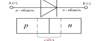
A semiconductor diode is an electronic device that has the property of unidirectional conductivity.
The diode has two terminals. One is called the cathode, which is negative. The other output is the anode. It is positive.
At the physical level, the diode is a single pn junction.
Let me remind you that semiconductor devices can have several pn junctions. For example, the dinistor has three of them! A semiconductor diode is essentially the simplest electronic device based on just one pn junction.
Let us remember that the operating properties of the diode appear only when connected directly. What does direct connection mean? This means that a positive voltage (+) is applied to the anode terminal, and a negative voltage is applied to the cathode, i.e. ( — ). current begins to flow through its pn junction .
When turned on in reverse, when a negative voltage ( - ) is applied to the anode and a positive voltage (+) is applied to the cathode, the diode is closed and does not allow current to pass through .
This will continue until the voltage on the reverse-connected diode reaches a critical value, after which damage to the semiconductor crystal occurs. This is the main property of the diode - one-way conductivity.
The vast majority of modern digital multimeters (testers) have the ability to test a diode in their functionality. This function can also be used to test bipolar transistors. It is indicated in the form of a diode symbol next to the marking of the multimeter mode switch.
A little note! It is worth understanding that when checking diodes in direct connection, the display does not show the transition resistance, as many people think, but its threshold voltage ! It is also called the voltage drop across the pn junction . This is the voltage above which the pn junction opens completely and begins to pass current. If we draw an analogy, this is the amount of effort aimed at opening the “door” for electrons. This voltage ranges from 100 to 1000 millivolts (mV). This is what the device display shows.
In reverse connection, when the negative ( - ) terminal of the tester is connected to the anode, and the positive (+) terminal is connected to the cathode, then no values should be shown on the display. This indicates that the junction is working properly and does not allow current to flow in the opposite direction.
In the documentation (datasheets) for imported diodes, the threshold voltage is referred to as Forward Voltage Drop (abbreviated Vf ), which literally translates as “ voltage drop in direct connection .”
The voltage drop across the pn junction itself is undesirable. If we multiply the current flowing through the diode (direct current) by the magnitude of the voltage drop, then we get nothing more than power dissipation - the power that is uselessly spent on heating the element.
You can find out more about the diode parameters here.
Diode check.
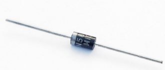
To make it more clear, let’s check the 1N5819 rectifier diode. This is a Schottky diode. We will soon see this.
We will perform the test using the Victor VC9805+ multitester. Also, for convenience, a solderless breadboard is used.
I draw your attention to the fact that during measurements you cannot hold the leads of the element being tested and the metal probes with both hands. This is a big mistake. In this case, we measure not only the parameters of the diode, but also the resistance of our body. This can significantly affect the result of the test.
You can hold the probes and terminals of the element with only one hand! In this case, only the measuring device itself and the element being tested are included in the measuring circuit. This recommendation is also valid when measuring the resistance of resistors, as well as when checking capacitors. Don't forget this important rule!
So, let's check the diode in direct connection. In this case, we connect the positive probe (red) of the multimeter to the anode of the diode. the negative probe ( black ) to the cathode. In the photo shown earlier, you can see that the cylindrical body of the diode has a white ring on one edge. It is on this side that it has a cathode terminal. This is how the cathode terminal of most imported diodes is marked.
As you can see, the threshold voltage value for 1N5819 appeared on the display of the digital multimeter. Since this is a Schottky diode, its value is small - only 207 millivolts (mV).
Now let's check the diode in reverse connection. We remind you that when switched in reverse, the diode does not allow current to pass through. Looking ahead, we note that in the reverse connection, a small current still flows through the pn junction. This is the so-called reverse current ( Irev ). But it is so small that it is usually not taken into account.
Let's change the connection of the diode to the multimeter's test leads. We connect the red probe to the cathode, and the black probe to the anode.
The display will show “ 1 ” in the most significant digit of the display. This indicates that the diode does not pass current and its resistance is high. Thus, we checked the 1N5819 diode and it turned out to be fully functional.
Many people ask the question: “Is it possible to test a diode without desoldering it from the board?” Yes, you can. But in this case, it is necessary to remove at least one of its pins from the board. This must be done in order to exclude the influence of other parts that are connected to the diode being tested.
If this is not done, then the measuring current will flow through everything, including through the elements connected to it. As a result of testing, the multimeter readings will be incorrect!
In some cases, this rule can be neglected, for example, when it is clearly visible that there are no parts on the printed circuit board that could affect the test result.
Diodes used in power supplies. Selection and replacement.
Hi all . So I thought about it and compiled a short list of diodes used in power supplies. In your favorite power supply, replace a pair of diodes (if the overall power of the power transformer allows) and the power of the power supply from 250 watts will become 300. And 300 watts will become 350.
DIODES t=25 deg. Schottky TO-220 SBL2040CT 10A x 2 =20A 40V Vf=0.6V at 10A Schottky TO-247 S30D40 15A x 2 =30A 40V Vf=0.55V at 15A ultrafast TO-220 SF1004G 5A x 2 =10A 200V Vf=0.97V at 5A ultrafast TO-220 F16C20C 8A x 2 =16A 200V Vf=1.3V at 8A ultrafast SR504 5A 40V Vf=0.57 Schottky TO-247 40CPQ060 20A x 2 =40A 60V Vf=0.49V at 20A Schottky TO-247 STPS40L45C 20A x 2 =40A 45V Vf=0.49V ultrafast TO-247 SBL4040PT 20A x 2 =40A 45V Vf=0.58V at 20A Schottky TO-220 63CTQ100 30A x 2 =60A 100 Vf=0.69V at 30A Schottky TO-220 MBR2545CT 15A x 2 = 30A 45V Vf=0.65V at 15A Schottky TO-247 S60D40 30A x 2 =60A 40-60V Vf=0.65V at 30A Schottky TO-247 30CPQ150 15A x 2 =30A 150V Vf=1V at 15A Schottky TO-220 MBRP3045N 15A x 2 =30A 45V Vf=0.65V at 15A Schottky TO-220 S20C60 10A x 2 =20A 30-60V Vf=0.55V at 10A Schottky TO-247 SBL3040PT 15A x 2 =30A 30-40V Vf=0.55V at 15A Schottky TO -247 SBL4040PT 20A x 2 =40A 30-40V Vf=0.58V at 20A UltraFast TO-220 U20C20C 10A x 2 =20A 50-200V Vf=0.97V at 10A
Fast round FR101-107 1A 30A 50-1000V Vf=1.3V Fast FR151-157 1.5A 50A 50-1000v Vf=1.3V Fast FR201-207 2A 70A 50-1000V Vf=1.3V Fast PR1001-1005 1A 30A 5 0-600V Vf=1.2V Fast PR1501-1507G 1.5A 50A 50-1000V Vf=1.3V Mikhail.
PS. About the selection of diodes——- ——— Sometimes it becomes difficult to decide which diode to choose or what to replace the diode with. How to choose a diode, what parameters to compare diodes by. It seems that everything is simple, you need to set the same or better parameters. The diode parameters are indicated for sinusoidal current and when operating in pulsed circuits the parameters are slightly lower in current and voltage. Next, the total current of both diodes is indicated, but in fact half a period through one diode and another half a period through the second diode, 10A - 1 diode + 10A - 2 diode = equal to 10A total current to the load, and the diode says 20A total current. The next parameter, the voltage drop across the open diode, is denoted by Vf, PW = IA multiplied by U Vf. From this formula you can find out the following: how much power will be released on the diode when the selected current flows through it. When 2 diodes are connected in parallel, the current flowing can be increased, and the internal resistance decreases, the voltage drop across the open diode also decreases, and the power dissipation on the diode also decreases. Diodes heat up less. Guys write: spectre Apple wrote: 3. Schottky diodes can be parallelized. If the radiator allows it, screw a second assembly on the back side, if you don’t have a more powerful one at hand. Since the forward drop at the Schottky diode junction depends on the current, and the higher the current, the greater the voltage drop and the dependence there is very nonlinear, then by rectifying 30A with two diodes instead of one, we get less heat into the air. Therefore, I would say that it is not only possible, but often even useful. And one more thing about parallel diodes: you can only parallel diodes that are identical, and preferably from the same batch, otherwise it can only get worse due to different parameters. For the same reason, two 15A shots are not equal to one 30A, it is necessary to calculate 20 or 25 amperes at most, and it is better to use 20. Otherwise, the reliability of the operation of such a combination will leave much to be desired.
- 64893 views
Classification
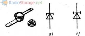
Diodes are simple semiconductor radioelements based on a pn junction. The figure shows a graphical representation of the most common types of these devices. Anode o, cathode - “-” (given for clarity; in the diagrams, a graphic designation is sufficient to determine the polarity).
Accepted notations
Types of diodes shown in the figure:
- A – rectifying;
- B – zener diode;
- C – varicap;
- D – microwave diode (high voltage);
- E – reversed diode;
- F – tunnel;
- G – LED;
- H – photodiode.
Now let's look at verification methods for each of the listed types.
Zener diodes
The issue of checking zener diodes stands apart. There is no point in checking them using the method described above, unless you can verify the integrity of the pn junction. Unlike a conventional rectifier diode, a zener diode uses the reverse branch of the current-voltage characteristic (VAC). Therefore, to study the stabilizing properties, the operating point must be shifted precisely to this section of the graph.
To do this, a simple circuit consisting of a power source and a current-limiting resistor is used. In this case, the multimeter measures not the junction resistance, but the voltage, with a smooth increase in the supply potential. A zener diode is considered working if, when the supply voltage increases, the potential difference at its electrodes remains constant and equal to that stated in the documentation for the device.
Checking the rectifier diode and zener diode
The protective diode, as well as the rectifier diode (including the power diode) or Schottky diode, can be checked using a multimeter (or use an ohmmeter); to do this, we switch the device to the continuity mode as shown in the photo.
Multimeter mode in which semiconductor rectifier diodes are tested
We connect the probes of the measuring device to the terminals of the radio element. By connecting the red wire (“+”) to the anode and the black (“-”) wire to the cathode, the multimeter (or ohmmeter) display will display the threshold voltage value of the diode being tested. After we change the polarity, the device should show infinitely high resistance. In this case, we can state that the element is in good condition.
If, when connecting back, the multimeter registers a leak, it means that the radio element has “burnt out” and needs to be replaced.
Note that this testing technique can be used to test diodes on a car generator.
Zener diode testing is carried out according to a similar principle, however, such a test does not allow one to determine whether the voltage is stabilized at a given level. Therefore, we need to assemble a simple circuit.
Testing using a regulated power supply
Designations:
- PSU – adjustable power supply (displaying load current and voltage);
- R – current-limiting resistance;
- VT – Zener diode or avalanche diode under test.
The verification principle is as follows:
- we assemble the circuit;
- set the multimeter mode, which allows you to measure DC voltage up to 200 V;
Selecting the required mode for testing
- turn on the power supply and begin to gradually increase the voltage until the ammeter on the power supply shows that current is flowing through the circuit;
- connect the multimeter as shown in the figure and measure the stabilization voltage.
Schottky diode assemblies in computer power supplies
During the assembly of power supplies and voltage converters for car amplifiers, a problem often arises with rectifying the current from the transformer. Getting hold of powerful pulsed diodes is quite a serious problem, so I decided to publish an article that provides a complete list and parameters of powerful Schottky diodes. Some time ago, I personally had a problem with the converter rectifier for a car amplifier. The converter is quite powerful (500-600 watts), the output voltage frequency is 60 kHz, any common diode that can be found in old trash will immediately burn out like a match. The only available option at that time was the domestic KD213A. The diodes are quite good, they hold up to 10 Amps, the operating frequency is within 100 kHz, but they also overheated terribly under load.
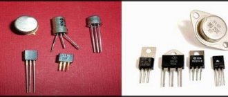
In fact, powerful diodes can be found in almost everyone. A computer power supply is a switching power supply that powers the entire computer. As a rule, they are made with a power from 200 watts to 1 kW or more, and since the computer is powered by direct current, this means that the power supply must have a rectifier. Modern power supplies use powerful Schottky diode assemblies to rectify the voltage - they have a minimal voltage drop across the transition and the ability to work in pulsed circuits, where the operating frequency is much higher than the network 50 Hz. Recently they brought several power supplies for free, from where the diodes were removed for this short review. In computer power supplies you can find a variety of diode assemblies; there are almost no single diodes here - in one case there are two powerful diodes, often (almost always) with a common cathode. Here are some of them:
D83-004 (ESAD83-004)
— A powerful assembly of Schottky diodes, reverse voltage 40 Volts, permissible current 30A, in pulse mode up to 250A - perhaps one of the most powerful diodes that can be found in computer power supplies.
STPS3045CW
— Dual Schottky diode, rectified current 15A, forward voltage 570 mV, reverse leakage current 200 μA, reverse voltage constant 45 Volts.
Varicap testing
Unlike conventional diodes, the pn junction of varicaps has a variable capacitance, the value of which is proportional to the reverse voltage. Checking for open or short circuits for these elements is carried out in the same way as for conventional diodes. To check the capacity, you will need a multimeter that has a similar function.
Demonstration of checking varicap
To test, you will need to set the multimeter to the appropriate mode, as shown in photo (A) and insert the part into the connector for capacitors.
As one of the commentators on this article correctly noted, it is indeed impossible to determine the capacitance of a varicap without using the rated voltage. Therefore, if there is a problem with identification by appearance, you will need to assemble a simple attachment for a multimeter (I repeat for critics, a digital multimeter with the function of measuring the capacitance of capacitors, for example UT151B).
Multimeter attachment for measuring varicap capacity
Designations:
- Resistors: R1, R2 -120 kOhm (yes, two resistors, yes in series, no, one cannot be replaced, parasitic capacitance, no further comment); R3 – 47 kOhm; R4 – 100 Ohm.
- Capacitors: C1 – 0.15 µF; C2 – 75 pF; C3 – 6…30 pF; C4 - 47 uF ha 50 volts.
The device requires configuration. It is quite simple, the assembled device is connected to a measuring device (a multimeter with a capacitance measurement function). Power must be supplied from a stabilized power source (important) with a voltage of 9 volts (for example, a Krona battery). By changing the capacitance of the substring capacitor (C2), we achieve a reading on the indicator of 100 pF. We will subtract this value from the device reading.
This option is not ideal, the need for its practical use is questionable, but the circuit clearly demonstrates the dependence of the varicap capacity on the rated voltage.
Defining an Element Type
It’s good if the size of the case allows you to put at least somewhat understandable markings on it. But most often the diodes are so small that it is difficult to mark them even with color. In this case, it is not possible to distinguish a diode from a zener diode, for example, because they are like twin brothers.
Read also: How to test a transformer for functionality
In such situations, only a schematic diagram of the apparatus from which the element was extracted will help. In accordance with it, you can determine the type of component and its brand. If this information is missing, you can try to search for a schematic diagram of the device being repaired on the Internet or take a photograph of the element and also go to the Internet and search by image.
Testing diodes with a multimeter or other tester should only be done after determining their type and brand, because different types are tested differently.
High Voltage Diode Testing
It will not be possible to check the high-voltage diode of a microwave oven in the same way as a regular one, due to its features. To test this element, you will need to assemble a circuit (shown in the figure below) connected to a 40-45 volt power supply.
Circuit for testing a diode used in a microwave oven
A voltage of 40-45 volts will be enough to test most elements of this type; the testing methodology is the same as for conventional diodes. The resistance value R should be in the range from 2 kOhm to 3.6 kOhm.
Basic Schottky diodes found in power supplies
Schottky TO-220 SBL2040CT 10A x 2 =20A 40V Vf=0.6V at 10A Schottky TO-247 S30D40 15A x 2 =30A 40V Vf=0.55V at 15A Ultrafast TO-220 SF1004G 5A x 2 =10A 200V Vf=0.97V at 5A Ultrafast TO-220 F16C20C 8A x 2 =16A 200V Vf=1.3V at 8A Ultrafast SR504 5A 40V Vf=0.57 Schottky TO-247 40CPQ060 20A x 2 =40A 60V Vf=0.49V at 20A Schottky TO-247 STPS 40L45C 20A x 2 =40A 45V Vf=0.49V Ultrafast TO-247 SBL4040PT 20A x 2 =40A 45V Vf=0.58V at 20A Schottky TO-220 63CTQ100 30A x 2 =60A 100 Vf=0.69V at 30A Schottky TO-220 MBR2545CT 15A x 2 = 30A 45V Vf=0.65V at 15A Schottky TO-247 S60D40 30A x 2 =60A 40-60V Vf=0.65V at 30A Schottky TO-247 30CPQ150 15A x 2 =30A 150V Vf=1V at 15A Schottky TO-220 MBRP3045N 15A x 2 =30A 45V Vf=0.65V at 15A Schottky TO-220 S20C60 10A x 2 =20A 30-60V Vf=0.55V at 10A Schottky TO-247 SBL3040PT 15A x 2 =30A 30-40V Vf=0.55V at 15A Schottky TO -247 SBL4040PT 20A x 2 =40A 30-40V Vf=0.58V at 20A Ultrafast TO-220 U20C20C 10A x 2 =20A 50-200V Vf=0.97V at 10A
There are also modern domestic diode assemblies for high current. Here are their markings and internal diagram:
High-voltage Schottky diodes are also produced, which can be used, for example, in power supplies for tube amplifiers and other equipment with high power supply. The list is given below:
Although it is more preferable to use Schottky diodes in low-voltage powerful rectifiers with output voltages of a couple of tens of volts at high switching frequencies.
Source: tehnoobzor.com
Tunnel and reverse diodes
Considering that the current flowing through a diode depends on the voltage applied to it, testing consists of analyzing this dependence. To do this, you will need to assemble a circuit, for example, such as shown in the figure.
Testing tunnel type diodes
List of elements:
- VD – tunnel type diode under test;
- Up – any galvanic power source with a discharge current of about 50 mA;
- Resistances: R1 – 12Ω, R2 – 22Ω, R3 – 600Ω.
The measurement range set on the multimeter should not be less than the maximum current of the diode; this parameter is indicated in the datasheet of the radio element.
Video: Example of checking a diode with a multimeter
Testing algorithm:
- the maximum value is set on variable resistor R3;
- the element under test is connected, observing the polarity indicated on the diagram;
- By decreasing the value of R3, we observe the readings of the measuring device.
If the element is working properly, during the measurement process the device will show an increase in current up to Imax of the diode, followed by a sharp decrease in this value. With a further increase in voltage, the current will decrease to Imin, after which it will begin to increase again.
Checking the LED spotlight
First, take a look at which LED is installed in the spotlight, if you see one yellow square, as in the photo below, then you won’t be able to check it with a tester, the voltage of such light sources is high - 10-30 Volts or more.
You can check the performance of this type of LED using a known-good driver for the appropriate current and voltage.
If many small SMDs are installed, checking such a spotlight with a multimeter is possible. First you need to disassemble it. In the case you will find a driver, moisture-proof gaskets and a board with LED. The design and testing process are similar to the LED lamp described above.
LED testing
Testing LEDs is practically no different from testing rectifier diodes. How to do this was described above. We check the LED strip (more precisely, its SMD elements), infrared LED, and also laser LED using the same method.
Unfortunately, a powerful radio element of this group, which has a higher operating voltage, cannot be tested using the indicated method. In this case, you will additionally need a stabilized power source. The testing algorithm is as follows:
- We assemble the circuit as shown in the figure. The power supplies are set to the operating voltage of the LED (indicated in the datasheet). The measuring range on the multimeter should be up to 10 A. Note that you can use the charger as a power supply, but then you need to add a current-limiting resistor;
Measuring the rated current on an LED
- measure the rated current and turn off the power supply;
- set the multimeter mode, which allows you to measure DC voltage up to 20 V, and connect the device in parallel to the element under test;
- turn on the power supply and remove the operating voltage parameters;
- We compare the data obtained with those indicated in the datasheet, and based on this analysis we determine the performance of the LED.
Operating principle
The operating principle of a Schottky diode is almost no different from semiconductor diodes. A special feature is the presence of metal. A typical semiconductor uses two substances that form electrons with a positive and a negative charge inside them. When an electric current passes, part of the charge is lost to the formation of these electrons.
A Schottky diode uses a metal and a semiconductor. Gold, silicon, and germanium are used as metal barriers in production. A diode also consists of an anode and a cathode. When voltage is applied to the anode, the metal creates a magnetic barrier to the direct passage of voltage. Electrons with a negative charge are created on its surface. When a significant magnetic field is formed, the element is pulsedly discharged. Such a discharge can be repeated an infinite number of times, subject to the operating voltage and temperature.
The most comfortable voltage for this type of diode is 40–60 volts. It is this voltage that allows the transition to be made without losing a fraction of the voltage and without increasing the temperature.
Temperature also plays a significant role in the rapid transfer of charges. When the input voltage is low, a temperature rise is created. Due to this, the number of charged electrons increases, which quickly overcome the metal barrier.
Checking the photodiode
In a simple test, the reverse and forward resistance of a radio element placed under a light source is measured, after which it is darkened and the procedure is repeated. For more accurate testing, you will need to take the current-voltage characteristic; this can be done using a simple circuit.
An example of a circuit for measuring current-voltage characteristics
To illuminate the photodiode during testing, you can use an incandescent lamp with a power of 60 W or more as a light source or bring the radio component to a chandelier.
Photodiodes sometimes have a characteristic defect, which manifests itself in the form of a chaotic change in current. To detect such a malfunction, it is necessary to connect the element under test as shown in the figure and measure the reverse current for a couple of minutes.
Testing for "creep"
If during testing the current level remains unchanged, then the photodiode can be considered working.
Testing without desoldering.
As practice shows, it is not always possible to test a diode without desoldering it when it is on the board, like other radio components (for example, a transistor, capacitor, thyristor, etc.). This is due to the fact that elements in the circuit may produce an error. Therefore, before checking the diode, it must be desoldered.
Today we can’t live without electronics. It is an integral part of any modern device or gadget. At the same time, all devices, sadly, cannot work forever and periodically break down. One of the fairly common causes of failure of a number of electrical appliances is the failure of an electrical element such as a diode.
You can check the serviceability of this component yourself at home. This article will tell you how to test a diode with a multimeter, as well as what these elements are and what the measuring device itself is.
PhiX › Blog › REPAIR OF COMPUTER POWER SUPPLY SUPPLY
In this article, I will talk a little about the basics of repairing computer, switching power supplies of the ATX standard. This is one of my first articles, I wrote it about 5 years ago, so I ask you not to judge strictly.
Precautionary measures.
Repairing switching power supplies is a rather dangerous task, especially if the fault concerns the hot part of the power supply. Therefore, we do everything thoughtfully and carefully, without haste, in compliance with safety precautions.
Power capacitors can hold a charge for a long time, so do not touch them with bare hands immediately after turning off the power. Under no circumstances should you touch the board or heatsinks while the power supply is connected to the network.
In order to avoid fireworks and preserve still living elements, you should solder a 100-watt light bulb instead of a fuse. If, when the power supply is turned on, the lamp flashes and goes out, everything is fine, but if, when turned on, the lamp lights up and does not go out, there is a short circuit somewhere.
The power supply should be checked after repairs are made away from flammable materials.
Soldering iron, solder, flux. A soldering station with power adjustment or a pair of soldering irons of different power is recommended. A powerful soldering iron is needed for soldering transistors and diode assemblies that are located on radiators, as well as transformers and chokes. Various small things are soldered with a soldering iron of lower power. Solder suction and/or braiding. Serve to remove solder. Screwdriver Side cutters. Used to remove plastic clamps that hold wires together. Multimeter Tweezers 100W light bulb Purified gasoline or alcohol. Used to clean the board from traces of soldering. BP device.
A little about what we will see when we open the power supply.
Internal image of an ATX system power supply
A – diode bridge, used to convert alternating current to direct current
B – power capacitors, used to smooth the input voltage
Between B and C there is a radiator on which the power switches are located
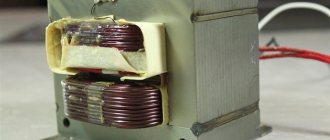
C – pulse transformer, serves to generate the required voltage ratings, as well as for galvanic isolation
between C and D – radiator on which rectifier diodes of output voltages are located
D – group stabilization choke (GS), used to smooth out noise at the output
E – output, filtering, capacitors, used to smooth out noise at the output
Pinout of the 24 pin connector and voltage measurement.
We will need knowledge of the contacts on the ATX connector to diagnose the power supply. Before starting repairs, you should check the voltage of the standby power supply; in the figure, this contact is marked in blue + 5V SB, usually this is a purple wire. If the duty station is in order, then you should check the presence of the POWER GOOD signal (+5V), in the figure this contact is marked in gray, PW-OK. Power good appears only after the power supply is turned on. To start the power supply, we close the green and black wires, as in the picture. If PG is present, then most likely the power supply has already started and the remaining voltages should be checked. Please note that output voltages will vary depending on the load. So, if you see 13 volts on the yellow wire, do not worry, it is likely that under load they will stabilize to the standard 12 volts.
If you have a problem in the hot part and need to measure voltages there, then all measurements must be carried out from the common ground, this is the minus of the diode bridge or power capacitors.
The first thing to do is open the power supply and perform a visual inspection.
If the power supply is dusty, clean it. We check whether the fan is spinning; if it is, then this is most likely the reason for the failure of the power supply. In this case, you should look at diode assemblies and DGS. They are most prone to failure due to overheating.
Next, we inspect the power supply unit for burnt elements, PCB darkened by temperature, swollen capacitors, charred DGS insulation, broken tracks and wires.
Before opening the power supply, you can try to turn on the power supply to be sure of the diagnosis. A correct diagnosis is half the treatment.
The power supply does not start, there is no standby voltage. The power supply does not start, but the standby voltage is present. No PG signal. The power supply goes into defense, the power supply works, but it stinks. The output voltages are too high or low . Fuse.
Source: www.drive2.ru
Diode diode discord
A standard diode is a component of the electrical network and acts as a pn junction semiconductor. Its structure allows current to pass through the circuit in only one direction - from the anode to the cathode (different ends of the part). To do this, you need to apply “+” to the anode and “-” to the cathode.
Note! Electric current in diodes cannot flow in the opposite direction, from the cathode to the anode.
Due to this feature of the product, if you suspect a breakdown, it can be checked with a tester or multimeter. Today there are several types of diodes in radio electronics:
How to check without desoldering
In order to connect the multimeter probes to the connectors in the PNP block, you need to solder small fragments of a regular paper clip onto them. Between the wires on which the paper clips are soldered, for insulation, you can install a small textolite gasket and wrap it with electrical tape. Thus, we get a simple design and reliable adapter for connecting probes.
Next, you need to connect the probes to the legs of the LED without removing it from the product circuit. Instead of a tester, to check the LED diode, you can use one Krona battery, or several AA batteries. The connection is carried out in the same way, but instead of an adapter, you can use small alligator clips to connect to the battery outputs of the probes.
Let's look at a specific example of how to check an LED without desoldering it from the circuit.
How is the check carried out?
After we have figured out the semiconductors of the electrical circuit and the purpose of the device, we can answer the question “how to check the diode for serviceability?” The whole point of checking diodes with a multimeter is their one-way electrical current carrying capacity. If this rule is observed, the electrical circuit element is considered to function correctly and without failures. Conventional diodes and Schottky diodes can be easily tested using this device. To check this semiconductor element with a multimeter, you need to do the following manipulations:
- you need to make sure that your multimeter has a diode test function;
- If such a function is available, we connect the probes of the device to the side of the semiconductor from which the “ringing” will be carried out. If this function is missing, then use the switch to switch the device to 1 kOhm. You should also select the mode for measuring resistance;
- the red wire of the measuring device must be connected to the anode end, and the black wire to the cathode end;
- after this, you need to observe changes in the forward resistance of the semiconductor;
- we draw conclusions about the presence or absence of voltage
The unit can then be switched to check for leaks or high circuits. To do this, you need to change the location of the diode output. In this state, it is also necessary to evaluate the obtained values of the device.
Checking the LED strip
LED strip is a light source consisting of several LED elements. SDs are grouped in groups of three per site. Then the tape can be divided into segments of any length without compromising its performance characteristics.
To make sure it works, apply electric current to the contacts. The whole thing will light up if it is working properly. If only part is lit, the problem is in the conductive cable. It needs to be checked with a multimeter.
If a whole section of three LEDs does not light up, the problem is in these elements. Inspect each of them and measure the resistance of the resistor of the entire group.
The considered methods for checking LED diodes in lighting fixtures are simple - arm yourself with a multimeter or wires with a pair of AA batteries. If you find a faulty element, replace it or take it to a workshop.
Checking the diode bridge
Sometimes there is a situation when you need to check the functionality of a diode bridge. It looks like an assembly consisting of four semiconductors. They are connected in such a way that the alternating voltage supplied to two of the four soldered elements becomes direct. The latter is removed from the other two terminals. As a result, the alternating voltage is rectified and converted into constant voltage.
Essentially, the principle of verification in this situation remains the same as described above. The only feature here is the determination of which output the measuring device will be connected to. There are four connection options that you should call:
- conclusions 1 – 2;
- conclusions 2 – 3;
- conclusions 1 – 4;
- conclusions 4 – 3;
By checking each output, you will get four results. The obtained indicators should be evaluated according to the same principle as for an individual semiconductor.
How to check the LEDs in a flashlight
To check, you need to disassemble the flashlight and remove the board on which they are installed. The test is carried out using a tester with probes connected to the PNP connector. You don’t have to unsolder the LEDs, but connect the probe contacts to them directly on the board, but you must remember to maintain polarity.
You can also determine a broken LED by measuring the resistance in the connection diagram. For example, if the LEDs in a flashlight are connected in parallel, by measuring the resistance and getting a result close to zero on any of them, you can be sure that at least one of them is definitely faulty. After this, you can begin checking each of the LEDs using the methods described above.
Testing LEDs is not a complicated process, and anyone with a few working batteries and a couple of wires can test and determine if a particular device is faulty.
Analyzing the results
When checking diodes (regular and Schottky) with a multimeter, you will get a certain result. Now we need to understand what it could mean. Signs that indicate the health of the semiconductor include the following:
- when connecting a part of the electrical circuit to the device, the latter will output the value of the available direct voltage in this element;
Note! Different types of diodes have different voltage levels, which is why they differ. For example, for germanium products this parameter will be 0.3-0.7 volts
- when connected in the opposite way (the probe of the device to the anode of the product), zero will be recorded.
If these two indicators are met, then the semiconductor is working adequately and the cause of the failure is not in it. But if at least one of the parameters does not correspond, then the element is considered unusable and must be replaced. In addition, it should be borne in mind that it is not a breakdown, but a “leakage” that is possible. This unpleasant defect can appear during long-term use of the device or poor-quality assembly. If there is a short circuit or leakage, the resulting resistance will be quite low. Moreover, the conclusion must be made based on the type of semiconductor. For germanium elements, this indicator in this situation will range from 100 kilo-ohms to 1 mega-ohm, for silicon - thousands of mega-ohms. For rectifier semiconductors, this figure will be many times higher. As you can see, it is not so difficult to assess the performance of semiconductors in any electrical device on your own. The above principle is suitable for testing diode elements of various types and types. The main thing in this situation is to correctly connect the measuring device to the semiconductor and analyze the results obtained.
How to ring an LED lamp?
Any electrician has “ringed” an incandescent lamp many times, but how to check an LED lamp with a tester?
To do this, you need to remove the diffuser; it is usually glued. To separate it from the body you need a mediator, or a plastic card, it needs to be inserted between the body and the diffuser.
If you can’t do this, try warming the gluing area a little with a hairdryer.
How now to check an LED light bulb with a multimeter? In front of you will be a board with LEDs; you need to touch their terminals with the tester probes. Such SMDs light up dimly in diode testing mode (but not always). Another way to check serviceability is to test the battery with a Krona battery.
The crown produces a voltage of 9-12V, so check the diodes with short-term sliding touches to their poles. If the LED does not light up with the correct polarity, it needs to be replaced.
Application of the tester
The simplest, but no less effective, device for testing elements of electronic circuits, semiconductor diodes, including, is a radio component tester.
Moreover, this instrument is the most common among radio technicians due to its unpretentiousness, small weight and size parameters and the ability to measure almost any characteristics of radio elements and circuits important for repairs.
It is believed that digital multimeters, due to their accuracy and ease of use, are gradually replacing analog ones. However, you shouldn’t compromise on the accuracy of the old “tseshka”.
It already includes microcircuits, and bridge resistors have an error of 1-2% (this is very high accuracy even for integrated circuits). Therefore, to check the serviceability of a diode or transistor, there is no need to buy a new multimeter, if you have an analog one.
Digital display has taken root due to the lack of mechanical components in the multimeter. This increased its impact resistance and service life.
Checking diodes has been simplified with the advent of a sound signal, which allows you not even to pay attention to the display. Most multimeters have a special mode that allows you to literally and figuratively ring the diode. It is marked on the body with the corresponding sign.
Just insert the black plug into the COM connector, and the red plug into the resistance measurement connector (Ω), set the switch to diode testing mode, and you can start testing.