Semiconductor devices were used in radio engineering even before the invention of vacuum tubes. The inventor of radio, A. S. Popov, first used a coherer (a glass tube with metal filings) and then contact of a steel needle with a carbon electrode to detect electromagnetic waves.
This was the first semiconductor diode detector. Later, detectors were created using natural and artificial crystalline semiconductors (galena, zincite, chalcopyrite, etc.).
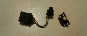
Such a detector consisted of a semiconductor crystal soldered into a holder cup and a steel or tungsten spring with a pointed end (Fig. 1). The position of the tip on the crystal was found experimentally, achieving the highest volume of the radio station transmission.
Rice. 1. Semiconductor diode - detector.
In 1922, O. V. Losev, an employee of the Nizhny Novgorod Radio Laboratory, discovered a remarkable phenomenon: a crystal detector, it turns out, can generate and amplify electrical oscillations.
This was a real sensation, but the lack of scientific knowledge and the lack of the necessary experimental equipment did not allow at that time to deeply explore the essence of the processes occurring in a semiconductor and to create semiconductor devices capable of competing with an electron tube.
Semiconductor diode
Semiconductor diodes are designated by a symbol that has been preserved in general terms since the days of the first radio receivers (Fig. 2.6).
Rice. 2. Designation and structure of a semiconductor diode.
The top of the triangle in this symbol indicates the direction of greatest conductivity (the triangle symbolizes the anode of the diode, and the short line perpendicular to the lead lines is its cathode).
The same symbol denotes semiconductor rectifiers, consisting, for example, of several diodes connected in series, parallel or mixed (rectifier columns, etc.).
Diode bridges
Bridge rectifiers are often used to power radio equipment. The outline of the same diode connection diagram (a square, the sides of which are formed by diode symbols) has long become generally accepted, therefore, to designate such rectifiers, a simplified symbol began to be used - a square with the symbol of one diode inside (Fig. 3).
Rice. 3. Designation of the diode bridge.
Depending on the value of the rectified voltage, each arm of the bridge can consist of one, two or more diodes. The polarity of the rectified voltage is not indicated on the diagrams since it is clearly determined by the diode symbol inside the square.
Bridges are structurally combined in one housing and are depicted separately, showing that they belong to one product in a positional designation. Next to the positional designation of diodes, like all other semiconductor devices, their type is usually indicated.
Based on the diode symbol, symbols for semiconductor diodes with special properties are built. To obtain the desired symbol, special characters are used, either on the basic symbol itself or in the immediate vicinity of it, and in order to focus attention on some of them, the basic symbol is placed in a circle - a symbol for the body of a semiconductor device.
How to distinguish a zener diode from a diode using a multimeter CAVR.ru
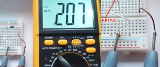
Share in: Very often a zener diode can be confused with a diode. How to distinguish a zener diode from a diode? Let's consider a simple circuit of an attachment for a multimeter, with the help of which you can not only distinguish a zener diode from a diode, but also determine the stabilization voltage of the zener diode (if it does not exceed 35V). The schematic diagram of the attachment is a dc-dc converter with galvanic isolation between the input and output. Generator with pulse width modulation (PWM) is made on a specialized microcircuit MC34063. To ensure galvanic isolation between the power source and the measuring part of the circuit, the control voltage is removed from the primary winding of the transformer. For this purpose, a rectifier is provided for vd2. The output voltage value (stabilization point) is set by selecting resistor r3. A voltage of about 40V is released at capacitor C4. Current stabilizer A2 and the zener diode being tested form a parametric stabilizer, and a multimeter connected to terminals X1 and X2 measures the voltage on this zener diode. When connecting the anode to “+” and the cathode to “-” of a diode or asymmetrical zener diode, the multimeter will show a very low voltage. If you connect in reverse polarity (like vdx in the diagram), then for the diode the multimeter reading will be about 40V, and for the zener diode the stabilization voltage (provided that it is below 40V). It is clear that for a symmetrical zener diode the stabilization voltage will be indicated for any connection polarity .Transformer T1 is wound on a ferrite toroidal core with an outer diameter of 23 mm. Winding 1 contains 20 turns, and winding 2 contains 35 turns of PEV 0.43 wire. It is important to lay turn to turn when winding. Moreover, the primary winding is wound on one part of the ring, and the secondary winding on the other. It is not recommended to superimpose one winding on another. When setting up, instead of the vdx zener diode, connect a resistor with a nominal value of 10 kOhm and by selecting resistance r3, ensure that a voltage of 40 V is established on capacitor C4. Printed circuit board: Section: [Measuring equipment] Save the article in: Leave your comment or question:
Tunnel diodes
A sign resembling a straight bracket denotes the cathode of tunnel diodes (Fig. 4a). They are made from semiconductor materials with a very high impurity content, as a result of which the semiconductor turns into a semimetal. Due to the unusual shape of the current-voltage characteristic (it has a section of negative resistance), tunnel diodes are used to amplify and generate electrical signals and in switching devices. An important advantage of these diodes is that they can operate at very high frequencies.
Rice. 4. Tunnel diode and its designation.
A type of tunnel diodes are reverse diodes, in which, at a low voltage at the pn junction, the conductivity in the reverse direction is greater than in the forward direction.
Such diodes are used in reverse connection. In the symbol for a reversed diode, the cathode line is depicted with two lines touching it with their middle (Fig. 4.6).
How to check the electrical stabilizer
This check is quite simple. To do this you need to take the following devices:
- Two table lamps.
- Stabilizer.
- Electric stove.
- Power extension cord with 3 sockets.
Check procedure:
- Insert the extension cord plug into a household outlet.
- Connect the stabilizer to an extension cord.
- Connect a 60 W table lamp to the stabilizer.
- Connect the electric hotplate to the extension cord.
If the stabilizer functions normally, then the operation of the tile will not affect the light of the light bulb, but if the lamp is connected directly to the extension cord, then when the tile is turned on, the light will become weaker. This is explained by the fact that a powerful consumer in the form of a tile significantly reduces the voltage and the lamp connected to the network before the device will produce less light. But a lamp powered after a voltage stabilizer will not respond to increased load.
Therefore, a situation may arise that when the voltage at the output of the voltage stabilizer decreases, the power will be sufficient to rotate the drum, but not enough to heat the water. In this case, it is necessary to turn off all unnecessary consumers and pour separately heated water into the machine.
Zener diodes
Semiconductor zener diodes, which also operate on the reverse branch of the current-voltage characteristic, have won a strong place in power supplies, especially low-voltage ones.
These are planar silicon diodes manufactured using a special technology. When they are turned on in the opposite direction and at a certain voltage, the junction “breaks through”, and subsequently, despite the increase in current through the junction, the voltage across it remains almost unchanged.
Rice. 5. Zener diode and its designation on the diagrams.
Thanks to this property, zener diodes are widely used as independent stabilizing elements, as well as sources of reference voltages in transistor stabilizers.
To obtain small reference voltages, the zener diodes are switched on in the forward direction, with the stabilization voltage of one zener diode equal to 0.7... 0.8 V. The same results are obtained when conventional silicon diodes are switched on in the forward direction.
To stabilize low voltages, special semiconductor diodes - stabistors - have been developed and are widely used. Their difference from zener diodes is that they operate on the direct branch of the current-voltage characteristic, i.e. when switched on in the forward (conducting) direction.
To show a zener diode in the diagram, the cathode dash of the basic symbol is supplemented with a short dash directed towards the anode symbol (Fig. 5a). It should be noted that the location of the stroke relative to the anode symbol should be unchanged regardless of the position of the zener diode symbol on the diagram.
This fully applies to the symbol of a two-anode (double-sided) zener diode (Fig. 5.6), which can be connected to an electrical circuit in any direction (in fact, these are two identical zener diodes connected back to back).
Diodes and their varieties
We very often use diodes in our circuits, but do you know how they work and what they are? Today, the “family” of diodes includes more than a dozen semiconductor devices called “diode”. A diode is a small container with evacuated air, inside which, at a short distance from each other, there is an anode and a second electrode - a cathode, one of which has electrical conductivity of type p, and the other - n.
To imagine how a diode works, let’s take as an example the situation of inflating a wheel using a pump. Here we are working with a pump, air is pumped into the chamber through the nipple, but this air cannot escape back through the nipple. Essentially, air is the same electron in a diode; an electron has entered, but it is no longer possible to get back out. If the nipple suddenly fails, the wheel will deflate and there will be a breakdown of the diode. And if we imagine that our nipple is working properly, and if we press the nipple pin to release air from the chamber, and press as we want and for how long, this will be a controlled breakdown. From this we can conclude that the diode passes current only in one direction (it also passes in the opposite direction, but very small)
The internal resistance of a diode (open) is not a constant value; it depends on the forward voltage applied to the diode. The higher this voltage, the greater the forward current through the diode, the lower its throughput resistance. You can judge the resistance of a diode by the voltage drop across it and the current through it. So, for example, if a direct current Ipr flows through the diode. = 100 mA (0.1 A) and at the same time the voltage across it drops 1V, then (according to Ohm’s law) the forward resistance of the diode will be: R = 1 / 0.1 = 10 Ohms.
I’ll note right away that we won’t go into details and go deep, draw graphs, write formulas - we’ll look at everything superficially. In this article we will consider the types of diodes, namely LEDs, zener diodes, varicaps, Schottky diodes, etc.
Diodes
They are indicated on the diagrams like this:
The triangular part is the ANODE, and the dash is the CATHODE. The anode is a plus, the cathode is a minus. For example, diodes are used in power supplies to rectify alternating current; with the help of a diode bridge, alternating current can be converted into direct current; they are used to protect various devices from incorrect polarity, etc.
The diode bridge consists of 4 diodes that are connected in series, and two of these four diodes are connected back to back, look at the pictures below.
This is exactly how a diode bridge is designated, although in some circuits it is designated as an abbreviated version:
~ outputs are connected to the transformer, in the diagram it will look like this:
The diode bridge is designed to convert, more often they say, to rectify alternating current into direct current. This type of rectification is called full-wave rectification. The operating principle of a diode bridge is to pass the positive half-wave of alternating voltage by positive diodes and cut off the negative half-wave by negative diodes. Therefore, a slightly pulsating positive voltage with a constant value is formed at the output of the rectifier.
To prevent these pulsations, electrolytic capacitors are installed. after adding a capacitor, the voltage increases slightly, but let’s not get distracted, you can read about capacitors here.
Diode bridges are used to power radio equipment and are used in power supplies and chargers. As I already said, a diode bridge can be made up of four identical diodes, but ready-made diode bridges are also sold, they look like this:
Schottky diode
Schottky diodes have a very low voltage drop and are faster than conventional diodes.
It is not recommended to install a regular diode instead of a Schottky diode; a regular diode can quickly fail. Such a diode is designated in the diagrams as follows:
Zener diode
The zener diode prevents the voltage from exceeding a certain threshold in a specific section of the circuit. It can perform both protective and restrictive functions; they only work in DC circuits. When connecting, the polarity must be observed. Zener diodes of the same type can be connected in series to increase the stabilized voltage or form a voltage divider.
Zener diodes in the diagrams are designated as follows:
The main parameter of zener diodes is the stabilization voltage; zener diodes have different stabilization voltages, for example 3V, 5V, 8.2V, 12V, 18V, etc.
Varicap
A varicap (or capacitive diode) changes its resistance depending on the voltage applied to it. It is used as a controlled variable capacitor, for example, for tuning high-frequency oscillatory circuits.
Thyristor
The thyristor has two stable states: 1) closed, that is, a state of low conductivity, 2) open, that is, a state of high conductivity. In other words, it is capable of transitioning from a closed state to an open state under the influence of a signal.
The thyristor has three terminals, in addition to the Anode and Cathode, there is also a control electrode - it is used to switch the thyristor to the on state. Modern imported thyristors are also produced in TO-220 and TO-92 cases.
Thyristors are often used in circuits to regulate power, to smoothly start motors or turn on light bulbs. Thyristors allow you to control large currents. For some types of thyristors, the maximum forward current reaches 5000 A or more, and the voltage value in the closed state is up to 5 kV. Powerful power thyristors of the type T143 (500-16) are used in control cabinets for electric motors and frequency converters.
Triac
A triac is used in systems powered by alternating voltage; it can be thought of as two thyristors that are connected back-to-back. The triac allows current to flow in both directions.
Light-emitting diode
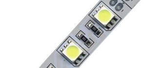
An LED emits light when electric current is passed through it. LEDs are used in instrument display devices, electronic components (optocouplers), cell phones for display and keyboard backlighting, high-power LEDs are used as a light source in flashlights, etc. LEDs come in different colors, RGB, etc.
Designation on the diagrams:
You can read more about LEDs here.
Infrared diode
Infrared LEDs (abbreviated IR diodes) emit light in the infrared range. The areas of application of infrared LEDs are optical instrumentation, remote control devices, optocoupler switching devices, and wireless communication lines. IR diodes are designated in the same way as LEDs.
Infrared diodes emit light outside the visible range, the glow of an IR diode can be seen and viewed, for example, through a cell phone camera, these diodes are also used in CCTV cameras, especially on street cameras so that the picture can be seen at night.
Photodiode
A photodiode converts light falling on its photosensitive region into electric current, and is used in converting light into an electrical signal.
Photo diodes (as well as photoresistors, phototransistors) can be compared to solar panels. They are designated on the diagrams as follows:
Varicaps
An electron-hole junction to which a reverse voltage is applied has the properties of a capacitor. In this case, the role of the dielectric is played by the pn junction itself, in which there are few free charge carriers, and the role of the plates is played by the adjacent layers of the semiconductor with electric charges of different signs - electrons and holes. By changing the voltage applied to the pn junction, you can change its thickness, and therefore the capacitance between the layers of the semiconductor.
Rice. 6. Varicaps and their designation on circuit diagrams.
This phenomenon is used in special semiconductor devices - varicaps [from the English words vari (able) - variable and cap (acitor) - capacitor]. Varicaps are widely used for tuning oscillatory circuits, in automatic frequency control devices, and also as frequency modulators in various generators.
The conventional graphic designation of a varicap (see Fig. 6, a) clearly reflects their essence: parallel lines at the bottom are perceived as a symbol of a capacitor. Kick and variable capacitors, varicaps are often made in the form of blocks (they are called matrices) with a common cathode and separate anodes. For example in Fig. 6.6 shows the designation of a matrix of two varicaps, and Fig. 6,c - out of three.
Preface
I live in a rural area, and we have periodic blackouts here, especially in the summer. The minimum time to restore power is 1 hour, the average is 3-4 hours if the emergency crew is not busy. Therefore, when I was doing renovations a few years ago, I made additional wiring of 12V lines in the apartment for duty and emergency lighting, as well as power supply for USB chargers built into the sockets. Initially, as a redundant power supply I used a 6A BIRP, which I got for an inexpensive price, and two 7Ah batteries in it. This, in principle, was enough to wait for the power supply to be restored. But the appetites came during the meal, LED lighting, a DVR, routers-shmouters were added... And all this already went past the BIRP, which was inconvenient. And besides, AGM batteries were very reluctant to give out high current, and they began to last a little more than a year. And taking into account the increase in their cost, it became generally sad.
Thyristors
thyristors are also based on the basic diode symbol (from the Greek thyra - door and English (resi) stor - resistor). These are diodes, which are alternating layers of silicon with electrical conductivity types p and p. There are four such layers in a thyristor, i.e. it has three pn junctions (pppp structure).
Thyristors have found wide application in various AC voltage regulators, relaxation generators, switching devices, etc.
Rice. 7. Thyristor and its designation on circuit diagrams.
Thyristors with leads only from the outer layers of the structure are called dynistorimn and are designated by a diode symbol crossed out by a line segment parallel to the cathode line (Figure 7, a). The same technique was used in constructing the designation of a symmetrical dinistor (Fig. 7, b), conducting current (after switching on) in both directions.
Thyristors with an additional (third) output (from one of the internal layers of the structure) are called thyristors. Control along the cathode in the designation of these devices is shown by a broken line attached to the cathode symbol (Fig. 7, c), along the anode - by a line extending one of the sides of the triangle symbolizing the anode (Fig. 7, d).
The symbol for a symmetrical (bidirectional) triistor is obtained from the symbol for a symmetrical dinistor by adding a third terminal (Fig. 7, (5).
How to find out how much Zener diode without an regulated power supply
This is really more difficult, but in some cases it is possible. You can use a cell phone charger, or a car battery charger. But it’s best to have several batteries available, gradually assemble a battery from them and measure the voltage on them and compare them with the voltage on the zener diode, a budget option, but a working one. The main condition is that you can’t do without a multimeter. Be interested in such questions, and difficulties will become possible.
Today we have learned ways to determine the value of a zener diode; if anyone has any thoughts on this and other issues, write, we’ll read and discuss everything.
Surge Protectors
- These are electronic devices with a complex structure, which means they have different functionality and possible malfunctions. There are various incidents in their work that are associated with the greatest loads, and there are also real breakdowns. These concepts should be distinguished, for which there are several tips.
First of all, let's look at how you can perform a quality check of the operation of this device. The most reliable method of monitoring the quality of a device is a conventional voltmeter, which can measure the voltage in the apartment network, as well as the voltage at the output of the device. In a home outlet, the voltage can fluctuate in the range of 170-240 volts, and at the output of the stabilizing device it should be equal to.
But not everyone uses a simple method of checking the operation of a voltage stabilizer, since they trust the data from the indicator. But this trust is not always justified, and sometimes on Chinese devices the digital indicator is simply connected directly to the relay. In this case, the relays have a fairly large step, and it will always show 220 V. In fact, the output will have a completely different value.
Photodiodes
The main part of a photodiode is a junction that operates under reverse bias. Its body has a window through which the semiconductor crystal is illuminated. In the absence of light, the current through the pn junction is very small - it does not exceed the reverse current of a conventional diode.
Rice. 8. Photodiodes and their representation on diagrams.
When the crystal is illuminated, the reverse resistance of the junction drops sharply, and the current through it increases. To show such a semiconductor diode in a diagram, the basic symbol of the diode is placed in a circle, and next to it (top left, regardless of the position of the symbol) the sign of the photoelectric effect is depicted - two oblique parallel arrows directed towards the symbol (Fig. 8a).
In a similar way, it is not difficult to construct a symbol for any other semiconductor device that changes its properties under the influence of optical radiation. As an example in Fig. 8.6 shows the designation of the photodinistor.
Basic semiconductor faults
Diodes can fail for various reasons . The most common of them are: increased current flowing through the circuit, exceeding the maximum reverse voltage value, and others (for example, thermal or mechanical effects). The main faults of these semiconductors are breakdown and breakage. Both faults can be identified using a multimeter. During a breakdown, a multimeter connected to the element in resistance measurement mode shows a minimum resistance of the order of several ohms. If there is a break, the measuring device in the same mode will show infinite resistance both with direct and reverse connections.
LEDs and LED indicators
Semiconductor diodes that emit light when current passes through a pn junction are called LEDs. Such diodes are turned on in the forward direction. The conventional graphic symbol of an LED is similar to the photodiode symbol and differs from it in that the arrows indicating optical radiation are placed to the right of the circle and directed in the opposite direction (Fig. 9).
Rice. 9. LEDs and their representation on diagrams.
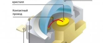
To display numbers, letters and other characters in low-voltage equipment, LED character indicators are often used, which are sets of light-emitting crystals arranged in a certain way and filled with transparent plastic.
ESKD standards do not provide symbols for such products, but in practice they often use symbols similar to those shown in Fig. 10 (seven-segment indicator symbol for displaying numbers and a comma).
Rice. 10. Designation of LED segment indicators.
As you can see, such a graphic designation clearly reflects the actual location of the light-emitting elements (segments) in the indicator, although it is not without a drawback: it does not carry information about the polarity of the inclusion of the indicator terminals in the electrical circuit (indicators are produced both with an anode terminal common to all segments and and with a common cathode terminal).
However, this usually does not cause any particular difficulties, since the connection of the common output of the indicator (as well as the microcircuits) is specified in the diagram.
AC rectification.
Let's replace the DC power source with an AC source of similar voltage.
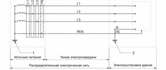
The light will light up, but dimly, with a slight flicker. As you know, alternating current with a frequency of 50 Hz. smoothly changes its direction 50 times per second. The diode will pass half-waves directed in its forward direction, and cut off those directed in the opposite direction. In the figure below, negative half-waves are shown in blue for clarity, and positive half-waves are shown in red. Thus, the light bulb will receive a rectified voltage, pulsating at twice the frequency. The resulting voltage will be slightly lower than the nominal voltage. For better rectification of alternating current, a so-called bridge circuit is used, consisting of four diodes in a single-phase circuit.
In a three-phase AC circuit, the positive branch of the diode bridge looks like this:
For reliable operation, when designing power supplies, semiconductor diodes are selected with a 50% margin in terms of Uform.i parameters. and Jpr. This is due to the fact that when operating at maximum currents, the reliability of the rectifier decreases due to heating of the pn junctions.