1.1. Switches on bipolar transistors
Table of contents
1. Keys on bipolar transistors……………………………………………………………………………………. 2
1.1.General information…………………………………………………………………………………………. 2
a) Ideal key…………………………………………………………………………………………. 2
b) Real key………………………………………………………………………………………….. 2
c) Transistor switch circuits………………………………………………………………………………………. 3
1.2.Model of a bipolar transistor………………………………………………………………………………….. 3
1.3.Operating mode of bipolar npn transistor…………………………………………………. 4
1.Active mode:…………………………………………………………………………………. 4
2.In cut-off mode:………………………………………………………………………………….. 4
2.a) In deep cut-off mode:………………………………………………………………. 4
2.b) Cut-off limit with active mode:………………………………………………………………. 5
3.In saturation mode:………………………………………………………………………………5
3.a) Saturation limit with active mode:………………………………………….. 5
4.Inverse mode……………………………………………………………………………….. 5
1.4.Transistor switch with OE……………………………………………………………………………………………….. 6
2. Residual parameters of the key on the BT………………………………………………………………………………… 9
2.1. Residual parameters of a closed transistor…………………………………………………………………… 9
2.2. Residual parameters of the saturated transistor……………………………………………. 12
3. Composite transistor switch………………………………………………………………………………… 15
3.1.???…………………………………………………………………………………………………………… 15
a) If transistor VT1 is locked, then…………………………………………………………. 17
b) If the transistor is saturated, then……………………………………………………………… 17
3.2.Multi-emitter transistor in switching mode…………………………………………. 19
a) Apply low voltage to any input……………………………………………………… 20
Designation of communication lines on electrical diagrams
But for them to work, a number of requirements must be met.
Find electric motors on the electrical diagram and determine their power supply system.
Not all circuits are considered electrical circuits. An active two-terminal network contains sources of electrical energy, while a passive two-terminal network does not contain them.
This switch responds to a specific word or tone of voice. What kind of circuit should be built, with two light bulbs, so that you can not light either of them, light only one, or light both? Before completing the next task, I would like to remind you of the Chinese wisdom: Tell me and I will forget... Give me the opportunity to act on my own and I will learn. An important distinctive property of elements of the second class is the presence of a section of the current-voltage characteristic that has a negative resistance, which ensures a regenerative avalanche-like transition of such elements from the off state to the on state, almost regardless of the parameters of the input switching signal. But what comes to the fore is the key switching speed, which determines the number of operations per unit of time, i.e. In reality, such ideal sources do not exist, but in practice they are trying to imitate them. Electric motors, lamps, tiles, and all kinds of electrical household appliances are called receivers or consumers of electrical energy.
Electrical circuit diagram - application and classification.
The discreteness of the partition is determined by the required approximation accuracy and the type of approximated function. Discuss Edit article Electrical devices are very important in the life of a modern civilized person. In practice, equivalent circuits are widely used during the operation of active and passive elements.
Output logic levels that characterize the key control circuits and their compatibility with digital ICs. Settling time of the output signal is the time during which the output signal, when switching, reaches a steady value with an acceptable error at a given load. If you use both modes, which have already been discussed, then based on their results the parameters of the active two-terminal network can be determined. A complex chain usually has several branches. This energy is replenished in the current source.
Depending on the value of the current source, the low level or high transistor must be in the closed cutoff mode or saturated static state. Elements with this characteristic used in electronics are very numerous and varied, but they are all united by the most important quality - the ability to operate in key mode. Problem on the law of conservation of energy in an electric circuit
2.2. Bipolar transistor model
Used to obtain the static current-voltage characteristics of the transistor. Based on an equivalent circuit (nonlinear).
The equivalent circuit and Ebers-Moll equations describe the static mode of an idealized transistor and are obtained under the following assumptions:
1) the volumetric resistance values of the base, emitter and collector are negligible;
;
— transfer coefficient.
2) the effect of modulation of the base width when the voltage at the base-collector junction changes is not taken into account (the efficiency of the emitter does not depend on the current);
3) the injection current density is low (the degree of base doping remains constant and low).
An example of transistor operation in switch mode
Gain is one of the main characteristics of a transistor. It is this parameter that shows how many times the current flowing through the emitter-collector channel is higher than the base one. Let's say the coefficient is 100 (this parameter is designated h21E). This means that if a current of 1 mA (base current) is supplied to the control circuit, then at the collector-emitter junction it will be 100 mA. Consequently, the incoming current (signal) was amplified.
We recommend reading: Coulomb's law: formula, definition, charge interaction force, coefficient
During operation, the transistor heats up, so it needs passive or active cooling - radiators and coolers. But heating occurs only when the collector-emitter passage does not open completely. In this case, a lot of power is dissipated - it needs to be put somewhere, you have to “sacrifice” the efficiency and release it in the form of heat. Heating will be minimal only in cases where the transistor is closed or fully open.
2.3. Operating mode of bipolar npn transistor
In any circuit, regardless of whether it operates in static or dynamic mode, the transistor at any given time operates in one of the following modes: active, cutoff, saturation, inverse.
Active mode:
The emitter junction is forward biased, the collector junction is reverse biased. Potential npn
BT:
| Rice. 1.3.a: ??? | ,; |
In cutoff mode:
The emitter and collector junctions are reverse biased. Potential cut-off criterion:,.
2.1) In deep cut-off mode:
if the voltage blocking the emitter and collector junctions significantly exceeds the temperature potential.
Potential criterion:
,;
,;
2.2) Cut-off limit with active mode:
if the collector junction is locked and the voltage at the emitter junction is “0”.
,;
In saturation mode:
both junctions are forward biased (double injection mode).
,;
3.1) Saturation limit with active mode:
if the emitter junction is forward biased and the voltage at the collector junction is zero:
,;
Inverse mode
called the mode when the emitter junction is biased in the opposite direction, and the collector junction is forward biased. In this case, the collector works as an emitter, i.e., it injects carriers into the base, and the emitter performs the functions of a collector.
,.
In transistor switches, the transistor can operate in all of the specified modes. If the BT operates in cut-off mode or in active mode at very low collector currents, then it is an open switch. If it operates in saturation mode or active mode at high collector currents, it acts as a closed switch. During the transition from one state to another, the BT operates in active mode.
Electrical manual controls
Manual control devices include low-power command devices - buttons and control keys, command devices and power switching devices (switches, batch switches and power controllers).
The control buttons are designed for the operator to apply a control action to the electronic device. They differ in size, number of closing and opening contacts, and shape of the pusher. Two, three or more buttons mounted in one housing form a button station (Fig. 1, a).
The contacts on the diagrams are depicted in the “normal” state of electrical devices, i.e. when they are not subject to mechanical, electrical, magnetic or any other influence. A feature of the control buttons is their ability to return to their original (normal) position (self-return) after the influence is removed. Buttons of the KU 120 and KE (KME) series are produced, designed for operation in AC and DC circuits. Based on KE buttons, PKE series control posts with one, two and three buttons are produced. Buttons and push-button stations have a degree of protection IP40, IP54 for various climatic versions and placement categories.
Figure 1 – Graphic and letter designations of control buttons (a), control keys (b), circuit breakers (d)
Control keys (universal switches) are designed to supply a control action to the electric drive and have two or more fixed handle positions and several make and break contacts (Fig. 1,b). In the middle position of the handle (position 0), the upper contact is closed, which is indicated by a dot in the diagram, and the two lower contacts are open. In position 1 of the handle, the middle contact closes and the rest open. The number of key contacts and the diagram of their operation can be very different.
The PE series control keys are designed for the same voltages and currents as the KE control buttons. Universal switches of the UP 5300, UP 5400 and PKU3 series are used for switching circuits of contactor coils, oil switches, and controlling multi-speed motors. They can switch up to 32 circuits and have up to eight control handle positions (positions).
Command controllers (command devices) are used for switching
several low-power (load current up to 16 A) electrical circuits. These devices, which have manual control from a handle or pedal with several positions, are widely used in electronic control circuits for crane mechanisms, metallurgical equipment, and transport.
Command devices are classified according to the number of switched circuits, the type of drive of the contact system, the number of operating positions of the handle (pedal), and the diagrams for turning on and off the contacts. Their electrical circuit is depicted similarly to the circuit of control keys and switches (Fig. 1).
General-purpose industrial control devices of the KA 410 A, KA 420 A, KA 4000, KA 4100, KA 4200, KA 4500, KA 4600, KA 11 series series are designed for switching DC circuits with voltages up to 440 V and AC circuits with voltages up to 500 V. controllers of the KKP 1000 and KKP 423 series are used to control electric drives of crane mechanisms and metallurgical equipment.
Switches are the simplest power switching devices, which are mainly designed for non-automatic infrequent closing and opening of power electrical circuits of DC and AC motors with voltage up to 500 V and current up to 5000 A. They differ in the strength of the switched current, the number of poles (switched circuits), the type of handle drive and the number of its positions (two or three). Switches of the P and RA series are designed for currents of 100...600 A, voltages of 220...660 V and have 1...3 poles.
Batch switches are a type of circuit breaker. Their contact system is assembled from separate packages according to the number of poles (switched circuits). The package consists of an insulator, in the grooves of which there is a fixed contact with screw terminals for connecting wires and a spring-loaded movable contact with a spark extinguishing device (the main advantage over switches).
The package switches produced are of the PV, PP, PGV series.
Controllers are multi-position electrical devices with hand or foot drive for direct switching of power circuits of DC and AC motors. The electronic controllers use two types of controllers: cam and magnetic.
In cam controllers, the opening and closing of contacts is ensured by cams mounted on the drum, which are rotated using a handle, handwheel or pedal. By profiling the cams, the required sequence of switching the contact elements is ensured.
Crane electric drives use cam controllers of the KKT-60A series to control asynchronous motors, designed for voltages up to 380 V, and the KB 100 series to control DC motors with voltages up to 440 V. Such controllers have up to 12 power contacts, designed for rated currents up to 63 A, as well as low-power contacts for switching control circuits.
Magnetic controllers are switching devices that include a command controller and power electromagnetic devices - contactors. The command controller, using its contacts, controls the contactor coils, which in turn switch the power circuits of the motors. The use of such a controller instead of a cam one allows you to increase the degree of automation of the electric drive, and, consequently, the productivity of the working machine or mechanism, and improve the working conditions of the operator, since controlling the electric drive using a command controller or a push-button station does not require much effort. The service life of magnetic controllers under the same conditions is also significantly higher than that of cam controllers, which is explained by the high switching capacity and wear resistance of electromagnetic contactors.
Automatic switches (automatic circuit breakers) - designed for infrequent operational switching on and off of electrical circuits (dozens of switchings per hour). They can have either a combined release, which protects circuits from short circuits and overloads, or only an electromagnetic release, which serves to protect against short circuits.
In agriculture, the most widely used are three-pole circuit breakers of the AE-2000, AE-2000M, A3700 series and the most modern VA-51 with a switching frequency of up to 30 starts per hour. The conventional graphic and letter designation of circuit breakers is presented in Figure 3, d.
2 Electrical remote control devices
Remote control devices include contactors, magnetic starters and relays, the contacts of which are switched when an electrical signal (voltage or current) is applied to their coils and this signal is removed. In other words, these are two-position switching devices with self-resetting, which are turned on and off by electrical signals.
Figure 2 - Contactor design (a), graphic designation of the electromagnetic coil (b), power contacts that close and open without arc extinguishing (c) and with arc extinguishing (d)
A contactor is an electromagnetic device designed for frequent remote switching of motor power circuits. Contactors differ in the type of current in the switched circuit, the number of main contacts (single-, double- and multi-pole), the type of current in the coil circuit (direct or alternating current control), rated current and voltage of the switched circuits, design and other characteristics.
The design of a single-pole DC contactor is shown in Figure 2. A retractor coil 12 is installed on the fixed core 14 of the magnetic system of the contactor. A moving main contact 5 is connected to the moving part of the magnetic system (the armature is connected to the armature, which is connected to the current circuit using a flexible conductor 7. When voltage is applied to coil 12 (closing contact 13), the armature is attracted to the core and contact 5 is closed with the fixed main contact 1, which ensures current switching. The necessary pressing of the main contacts in their operating position is provided by spring 6. In the process of contact of contacts 1 and 5, they roll and grind , which reduces the contact resistance.
Auxiliary (blocking) bridge-type contacts are also connected to the armature 8 - making 10 and breaking contacts, intended for operation in control circuits and designed for low currents. Blocking contacts 10 close and 11 open simultaneously with the closure of the main contacts.
The contactor is turned off by removing the voltage from coil 12 (contact 13 opens), while its moving system, under the influence of gravity and return spring 9, returns to the “normal” state. The electric arc that occurs when the main contacts are opened is extinguished in a slotted arc-extinguishing chamber 4 made of heat-resistant insulating material. To speed up the extinguishing of the arc, chambers with insulating partitions 3 can be used, and sometimes a spark arresting grid made of short metal plates 2 is installed.
DC contactors are manufactured with one or two poles for rated currents of the main contacts from 4 to 2500 A. The main contacts are capable of disconnecting overload currents of 7 ... 10 times the rated current. DC contactor coils have a large number of turns and have significant inductance, which makes it difficult to open their circuits.
Blocking contacts can disconnect currents up to 20 A at voltage, up to 500 V in the coil circuits of AC devices, and in the coil circuits of DC devices - currents up to 2.5 A at 110 V, up to 2 A at 220 V and up to 0.5 A at 440 V.
Figure 2 shows, respectively, the symbols of the contactor elements: retractor coil; making and breaking main contacts without arc extinguishing and with arc extinguishing. Symbol of auxiliary contacts Fig. 2, c.
According to the principle of their operation and basic design elements, AC contactors do not differ from DC contactors. A special feature of their operation is that the coil is powered by alternating current, which determines the increase in current when triggered several times compared to the current when the armature is retracted. For this reason, AC contactors are limited to the number of times they are switched on per hour (usually no more than 600). In addition, the pulsating magnetic flux created by the alternating current of the coil causes vibration and humming of the magnetic circuit, as well as its increased heating. To reduce these undesirable factors, the magnetic circuit is assembled from thin-sheet transformer steel, and a short-circuited turn is placed on the core or armature.
In AC contactors, the conditions for extinguishing the arc are simpler, which in this case is less stable and can go out when the alternating current of the load passes through zero. AC contactors are designated in electrical diagrams in the same way as DC contactors.
AC contactors of the KT 6000, KT 7000, KTP 600 series, designed for currents from 63 to 1000 A, have from two to five main contacts. Their coils are made for alternating current voltage from 36 to 500 V with a frequency of 50 Hz. A modification of these series are contactors of the KT 64, KTP 64, KT 65 and KTP 65 series, in which arcless switching is carried out by bridging the main contacts with thyristors during their opening. The absence of an arc when disconnecting contactors increases their reliability, wear resistance of the main contacts and explosion safety, which makes it possible, in particular, to increase the permissible number of their starts to 2000 per hour.
Universal, i.e. MK series contactors are used for switching power circuits of both direct and alternating current. Such contactors provide current switching up to 63 A in DC circuits with voltages up to 440 V and in AC circuits with voltages up to 660 V with a frequency of 50 and 60 Hz, having the number of main contacts from 1 to 3. Their pull-in coils are designed for direct current with a voltage of 24, 48, 110 and 220 V.
A magnetic starter is a specialized complex device designed primarily for controlling three-phase asynchronous motors, i.e., for connecting them to the network, disconnecting them, providing thermal protection and signaling about operating modes. In accordance with the functions of the starter, it may include a contactor, control buttons, thermal protection relays, and signal lamps located in one housing. Magnetic starters differ in purpose (irreversible and reversible), the presence or absence of thermal relays and control buttons, the degree of protection from environmental influences, the levels of switched currents, and the operating voltage of the main circuit.
Until recently, outdated designs of magnetic starters PME and PAE were widely used. They are gradually being replaced by more advanced series of PMA and PML.
Starters of the PML series are produced for currents from 10 to 200 A. The structure of the alphanumeric designation has the letter designation of the starter and six numbers (starter size, version, degree of protection, number of contacts of the auxiliary circuit, climatic version).
PML starters are equipped with three-pole thermal relays of the RTL type.
PMA starters are equipped with three-pole thermal relays of the PTT type.
To provide the required functions, they may have an isolation transformer, control buttons, an ammeter, and a signal lamp. Their mechanical wear resistance is (10...16)-106 cycles, and the switching frequency per hour is 6000 for starters of the first size and 2400 for starters of the fifth and sixth sizes.
An electromagnetic relay is a device designed for switching low-current control circuits of electric motors in accordance with the electrical signal supplied to its coil. The scope of application of the relay is very wide. They are used as current and voltage sensors, as well as intermediate elements for transmitting commands from one circuit to another and multiplying signals, as time sensors, output elements of various ED coordinate sensors and sensors for technological parameters of working machines and mechanisms. In other words, they perform a wide variety of control, monitoring and interlocking functions in an automated electronic device.
An electromagnetic relay operates similarly to a contactor (Fig. 3). On the core 2 of the magnetic relay system there is a coil 1, which is supplied with an input electrical signal. When the current (voltage) in the coil circuit exceeds a certain value, called the current (voltage) of the relay operation, the electromagnetic force created by it becomes greater than the opposing force of the return spring 10, the relay armature 3 is attracted to the core 2 and the traverse 6, having risen, ensures the closure of contacts 8 and opening of contacts 7. The pressing force in the contacts is created by spring 9. If you reduce (turn off) the current (voltage) in the coil, the armature, under the action of spring 10, will move to its original position; contacts 7,8 will return to their normal (original) position.
Since relay contacts switch small (5... 10 A) currents, they usually have a simple design without the use of arc chutes.
Figure 3 – Electromagnetic relay
Relays of the RP-250, RP-321, RP-341, RP-42 and a number of others series are also used as intermediate relays, which can also be used as voltage relays.
Reed electromagnetic relays have sealed contacts, which increases their wear resistance and operational reliability. Let's consider the design of a simple relay with a sealed contact - a reed switch (Fig. 4). Inside a sealed glass capsule 3 filled with an inert gas, there are fixed 1 and movable 2 contacts made of an iron-nickel alloy. Capsule 3 is covered by a magnetic circuit 5, on part of which a coil 4 is located. If a direct current with voltage U is applied to the coil 4, it will create a magnetic flux in the magnetic circuit 5 and contacts 1 and 2, under the influence of which the end of the movable contact 2 will move down and close with the contact 7, as a result of which the switched current circuit is closed.
When the voltage is removed from the coil, the magnetic flux will disappear and elastic contact 2 will return to its original position, opening the circuit. The wear resistance of relays with reed switches, capable of switching currents up to 5 A at voltages up to 100 V, reaches several tens of millions of operations.
Relays of the RES 42, RES 43, RES 44, RES 55 series based on KEM type reed switches allow switching currents up to 1 A at voltages up to 220 V.
Figure 4 – Reed electromagnetic relay
3.1. Residual parameters of a closed transistor
a) When the value of the blocking voltage at the emitter junction changes, that is, when the cutoff depth () changes, the base current does not change and remains equal. This equality is called the current cutoff criterion.
b) Both in the deep cutoff mode and at the cutoff boundary, the emitter current is .
The equivalent circuit of the key in cut-off mode can be represented as:
| Rice. 2.1.a: Equivalent circuit of a key in cut-off mode |
Switch output voltage
c) From the diagram it is clear that the voltage applied to the emitter, control junction depends on the residual base current;
.
In its turn .
To maintain the cutoff mode when changing from and resistances, it is necessary to fulfill the following condition:
.
Otherwise, despite the negative polarity of the control signal, the transistor will switch to active mode.
d) In transistor switches, it is necessary to use transistors with low reverse transition currents.
Note:
Integrated circuits do not use negative control signals to turn off transistors because digital circuits are single-supply powered. The open state of the key does not correspond to the cut-off mode, but to the active mode at low collector current. This has a beneficial effect on reducing the duration of transient processes.
|
The transistor turn-off threshold is a conditional value. The more open, the more can be selected. Usually accepted.
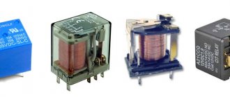
Electromagnetic relay
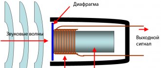
A relay is an electromagnet that controls a group of contacts. An analogy can be drawn with a conventional push-button switch. Only in the case of a relay, the force is taken not from the hand, but from the magnetic field that is located around the excitation coil. The contacts can switch a very large load - it all depends on the type of electromagnetic relay. These devices have become very widespread in automotive technology - with their help, all powerful consumers of electricity are turned on.
This allows you to divide all the electrical equipment of the car into a power part and a control part. The current consumption of the relay excitation winding is very small. And the power contacts are coated with precious or semi-precious metals, which eliminates the possibility of an arc. Transistor switch circuits for 12 volts can be used instead of relays. At the same time, the functionality of the device improves - the switching on is silent, the contacts do not click.
3.2. Residual parameters of a saturated transistor.
| Rice. 2.2.a Designation of voltages at the terminals of the transistor | ; |
a) The smallest of the residual stresses is . Therefore, it is desirable to use a switch such that the residual voltage is , that is, the preferred circuit is a switch with an OE.
b) Dependence of residual stresses on the degree of saturation
|
are the voltages at open junctions, they increase with increasing.
decreases with increase.
c) In real transistors, residual voltages depend on the voltage drops across the volumetric resistances of the layers. At high currents, the voltage drops increase.
Since the “K” layer has a large resistance and length??? the current through it is high, a hidden “n+” sublayer is introduced into the design of the epitaxial-planar transistor.
|
d) The weak dependence of interelectrode voltages on “N” allows us to present the equivalent circuit of a transistor in saturation mode in the following form:
Rice. 2.2.d: Equivalent circuit of a transistor in saturation mode |
;
.
Since residual voltages are small compared to the power supply voltage, they can often be neglected. The simplified equivalent circuit takes the form:
| Rice. 2.2.d: Transistor-equipotential point |
Parameters and maximum operating conditions of the transistor
Let us now finally check whether the selected transistor is suitable for us.
The maximum collector-emitter voltage must be higher than the switching voltage, and in the case of switching an inductive load, higher than the switching voltage, taking into account voltage surges with the selected damping circuit.
The maximum base current must be higher than our design control current.
The maximum collector current must be higher than the switching current.
The permissible peak power dissipation must be higher than the peak power dissipation at the moment of switching. The fact is that even if the average power dissipation is low, the large thermal energy released in a very short time during switching can destroy the bipolar transistor.
The permissible average power dissipation must be higher than the total average power dissipated by the switch.
The frequency recommended for the transistor should be higher than the switching frequency in the circuit.
The transistor's cooling system (heatsink or other heat dissipation system) must be able to dissipate the generated power.
For use as switches, it is better to select transistors with minimum saturation voltage collector - emitter, base - emitter, this will reduce power losses in the open state, minimal on and off times (resorption), this will reduce power losses when switching, maximum current transfer coefficient, this will reduce management losses.
4.1. ???
If the load of the OE key is a sufficiently large capacity, then the key has low performance.
Let's assume that the transistor in the key circuit turns off instantly.
Rice. 3.1.a: Key diagram after switching (previously it was saturated) |
The output voltage is the voltage across the capacitor.
The previously discharged capacity begins to charge with current.
The duration of the front is determined by the charging time of the capacitance, that is. Since it is several kOhms, the duration of the falling edge turns out to be unacceptably long.
| For example: ; . Then . |
To improve the parameters of the key, it is built according to the structural diagram:
Rice. 3.1.b: Key structure diagram |
In this circuit, there is a low-resistance circuit for charging.
The principle of operation of a composite key is as follows.
When a positive pulse arrives at the input, the OE switch closes and the OK switch opens. The load capacity is quickly discharged through a saturated OE switch. The output voltage is close to zero.
At the end of the positive pulse, the OE key opens and the OK key closes. Now the load capacity is charged through the saturated OK switch. Since the saturation current of the transistor is high, the capacitance is charged quickly.
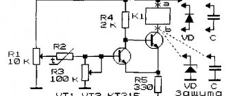
Rice. 3.1.c: Schematic diagram of a composite key |
A star key is assembled on transistor VT1, which represents a combination of OE and OK keys. The signal at the collector has a polarity opposite to the polarity of the input signal, that is, the collector circuit VT1 acts as an inverter. The emitter circuit VT1 does not invert the signal.
VT2 - OK key;
VT3 - OE key.
1) If transistor VT1 is locked, then
.
Since, transistor VT3 is also locked.
The voltage at the collector VT1 is:
and close to the supply voltage.
Therefore, transistor VT2 is open and the load capacitance in steady state is charged to voltage
,
where , is the voltage drop across the emitter junction of the open transistor VT2 and across the open diode VD1.
2) If the transistor is saturated, then
and transistor VT3 is also in saturation mode. In this case, VT2 must be locked. To do this, it is necessary that the voltage at its base be less than or equal to the voltage at the emitter or
From the last relationship it is clear that in the absence of a diode in the circuit, the condition for turning off transistor VT2 is not satisfied.
In this state of the key, the capacitance is discharged through the saturated transistor VT3 and the voltage across it (low level).
During the transition process, due to the delay in turning off the transistors, some transistors (both VT2 and VT3) are open for some time. This results in an inrush of current drawn by the key from the power supply. To limit this current, a small resistance is introduced into the collector circuit of transistor VT2
Often, transistor VT2 with diode VD is replaced with a composite transistor VT2′, VT2".
Rice. 3.1.d: Composite transistor VT2′, VT2" |
The principle of operation of the circuit does not change. The function of the bias diode VD here is performed by the emitter junction of transistor VT2.”
Content
The designation of thyristors and operational amplifiers is shown in the figure. Task 3.
Analyze the operation of each electrical circuit of the electrical circuit, identify the main and auxiliary devices on it, determine the conditions of their operation, and, if necessary, familiarize yourself with the technical documentation for electrical devices. In addition, analog switches are characterized by such parameters as maximum permissible modes, supply voltages, power consumption, operating temperature range, dimensions, housing type, etc. Matched mode It is used to ensure maximum transfer of active power that goes from the power source to the consumed energy .
The list of circuit components can be quite large.
The first is used both in static mode and in slowly changing processes. In addition, such devices, as a rule, have two stable quasi-stable states, during which only slowly changing processes are observed in the circuit, which makes it possible to calculate and analyze these devices using static equivalent circuits, the components of which are static equivalent circuits of devices.
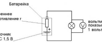
The arrow in the circle indicates the positive direction of the source current. Matched mode It is used to ensure maximum transfer of active power that goes from the power source to the consumed energy. There are two main ways to connect power supplies: series and parallel. In a household network we have a voltage of volts with certain normalized deviations.
The elements of the electrical circuit diagram are not used in this case. Not all circuits are considered electrical circuits. Designation of transistors in the diagram The electrical circuit of transistors - elements of the electrical system capable of controlling the current in the output circuit when exposed to the input signal, is shown in the figure. Ohm's law for a complete circuit It defines the relationship that is established between the emf E of the power source, whose internal resistance is equal to r, the current and the general equivalent R.
Additional
4.2. Multi-emitter transistor in switching mode
A multi-emitter transistor (MET) is designed to perform logical functions in a TTL element.
Rice. 3.2.a: Physical structure of a multi-emitter transistor??? |
The MET has several emitters (four in the above design), located in such a way that direct interaction between them through the disconnecting sections of the base is excluded. MET is several transistor structures that have a common collector.
Rice. 3.2.b: Connection circuit for a multi-emitter transistor |
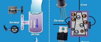
How a field-effect transistor works: 6 types - brief information
The classification shown in the picture below, where their types are structured, will help us deal with a specific field grass and understand its structure.
JFET and MOSFET have different structure. In JFET, the gate (Gate) is directly built into the cross section of the channel and works as a control pn junction.
For mosfet:
- there is an additional fourth pin connected internally to the housing. It is not used when connecting to external circuits;
- The gate output region is separated by a layer of silicon dioxide (dielectric) from the channel semiconductor. It works as a plate capacitively coupled capacitor. Due to this modification, it is called an “insulated gate” or MOS transistor.
MIS stands for metal-dielectric-semiconductor and MOS stands for metal-oxide-semiconductor. The difference between them for a novice electrician is not significant, practically absent.
In the diagrams, mosfet and jifet are designated in different ways. MOSFET is drawn with:
- the fourth pin, which is not connected anywhere;
- a shutter separated from the main channel.
Mosfets are manufactured with different substrates (channels), which can be depleted or enriched in major charge carriers.
I will not describe and describe in more detail the differences between each type of these semiconductors for a novice electrician: there is not much point.
Below are just typical schedules of their work. They will give a general idea of behavior, and you will need to take specific data from the datasheet - technical documentation.
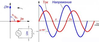
The amount of current flowing through the drain depends on the applied voltage between gate and source, as well as the ambient temperature.
The output drain current characteristics depend on the magnitude of the applied voltage between drain-source and gate-source.
This is how a MOS transistor with a built-in channel works. The current slope increases with increasing voltage Usi, Uzi.
And here are the characteristics of transistors with an induced channel.
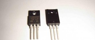
Before any check of each transistor, it is necessary to clarify its technical capabilities according to the factory documentation.
Such graphical images and dependencies of electrical engineering processes, due to their clarity, have better information content.
6 features of electronic devices using MOSFETs
Recently, we are increasingly working with mosfet-type field devices with a channel of any conductivity.
Let us briefly analyze such a scheme and its properties.
Point No. 1: which shoulder to place the load on?
When a semiconductor junction is fully open, a very small resistance of tens or hundreds of milliOhms (Ropen) is created between drain and source, which creates a low voltage drop across
and in this section (In·Ropen), where In is the value of the load current.
The voltage potential applied to the gate may not be sufficient to fully open the semiconductor. Therefore, the load is turned on higher on the drain side in an n-type field switch, and on the source side in a p-type field switch when the circuit is powered from a single source.
If the device uses additional voltage sources, then this requirement is not necessary.
Point No. 2: tricks for connecting a field worker to microcontrollers
For reliable operation of the MOSFET, it is necessary to apply a threshold voltage value between its gate and source (gate-source), which is indicated in the datasheet. It is usually around 10 volts. Still, digital devices work up to five: their power supply is not enough, you will need to add a level.
You can solve the problem in one of three ways:
- a key with bipolar transistors supplies the necessary power to the gate;
- connect a special driver (chip) to generate a control signal. They are designed for both the upper and lower shoulder to accommodate the load. Moreover, the high-side driver often uses a circuit to increase the output voltage;
- use a specialized low-level field operator (logic level). However, acquiring it can be problematic.
Point No. 3: how to avoid the influence of electrical interference
The appearance of any interference potential at the output of a transistor often leads to its unauthorized switching and disruption of electronic operating algorithms.
Therefore, the gate is always “pulled” to power or ground through a certain resistance, even when connected through a microcontroller. It should not be left in a free state, accessible to the penetration of extraneous interference.
We recommend reading: How a boost voltage converter works
Point No. 4: combating surge current when turned on
The natural presence of capacitance at the gate pin leads to a “current surge” each time the transistor is turned on. This can lead to damage to the semiconductor junction.
The problem is solved by introducing a resistor of sufficient value into the gate circuit. However, its value must be selected taking into account the increase in the key opening time.
Feature No. 5: inrush current protection when disconnecting inductive loads
A protective high-speed TVS diode, connected in parallel between the source and drain, reliably shunts the pulses created by disconnecting inductive loads.
When operating at high frequencies in bridge or half-bridge circuits of switching power supplies or induction heaters of hobs, a Schottky diode is connected counter-currently to the drain output, blocking the parasitic diode, because it increases the closing time, which can damage the semiconductor.
Point No. 6: additional MOSFET protection
Safe operation of a high-speed high-frequency switch in the switching mode of powerful inductive loads is ensured by its connection to snubber circuits. They:
- aperiodic currents created by transient processes close on themselves;
- reduce heating of semiconductors;
- protect the field switch from unauthorized opening during a rapid increase in voltage between drain and source.