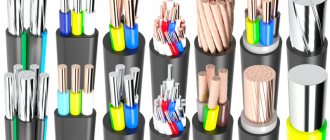
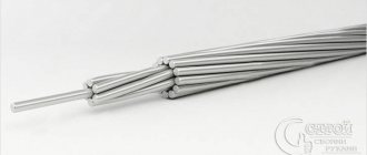
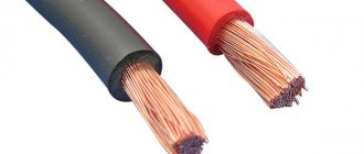
Aluminum wiring continues to be used in many older homes. It has many disadvantages and is unable to withstand the high loads associated with the operation of a large number of modern electrical appliances. When carrying out renovations on premises, most owners strive to make a 100% replacement with copper cable . But sometimes it’s not possible to completely remove outdated wiring , and you have to think about how to safely and correctly connect an aluminum wire to a copper one.
Proper Methods for Safe Connections in Electrical Wiring
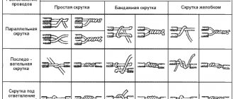
Since the chemical properties of copper and aluminum are significantly different, standard techniques are not suitable for combining them. There is an opinion that it is generally not worth connecting of wires . Yes, standard twisting is categorically unacceptable here, but other methods that do not allow contact of conductors, but allow the full integration of copper and aluminum wiring, are perfect.
Bolted connection via bolt and steel washers
A method with a high degree of reliability is a bolted connection, which even a non-professional can do. In this case, direct contact, which is undesirable for copper with aluminum, conductors of different sections can be combined.
To connect aluminum and copper wires to each other in this way, you will need:
- Bolt;
- Screw;
- Steel washers;
- Wrench.
It is worth understanding that a knot made in this way will turn out to be quite cumbersome, which makes the method not always convenient. It is unlikely to be acceptable in a small apartment junction box, but it is perfect for a general electrical panel where there is enough space.
How to connect aluminum wires to copper using the bolt method:
1. Remove the insulation layer from the cables being connected;
2. Shape the stripped ends into the shape of a ring;
3. Install a washer, a ring of the first wire, a washer, a ring of the second, a washer, a nut, tightened until it stops;
4. Apply insulation with tape.
Important! The washer must separate the aluminum and copper wires. When installing conductors of the same material, a washer is not needed.
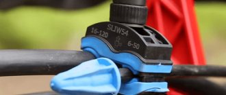
Terminal adapters and terminal blocks
Another solution for how to properly connect copper and aluminum wires is the use of terminals and terminal blocks. They consist of a transparent plastic housing with cells and clamping screws, inside of which a brass sleeve is placed. With one block you can connect a different number of pairs of conductors by selecting the required number of cells.
How to use terminal blocks to connect wires:
1. Unscrew the clamp screw;
2. Remove the insulating layer from the conductor;
3. Insert the cable into the terminal and tighten the clamping screw.
The same is done by fastening the cable on each side.
Important! When fixing with a clamping screw, it is important not to overdo it, since excessive force can damage the core .
WAGO terminal blocks for aluminum and copper with paste inside (or without paste)
Terminals from the German brand WAGO are well known to electricians and enjoy a high level of trust. For cables made of one material, the company produces terminal models with flat spring clamps and equipped with clamping levers. To connect aluminum and copper, WAGO offers a variety of 2273 series terminals with contact paste inside.
Since the characteristics of copper and aluminum are different, direct contact between them is prohibited. To eliminate this, contact paste is needed inside the terminals.
Important! Before connecting copper and aluminum conductors using WAGO terminals, the paste from the copper socket must be thoroughly cleaned.
It happens that terminal blocks are sold without paste.
In this case, such WAGO conductive paste for aluminum can always be purchased separately; it is called
WAGO “ALU-PLUS” art. 249-130
Alu-Plus contact paste from WAGO
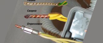
Method of crimping sleeves using press pliers: sleeves
Connecting wires by crimping with sleeves is a costly process, but it allows you to obtain a durable result, as well as reliable contact. You will need special sleeves that look like hollow tubes that act as a connector . Press pliers are also needed, which can be manual or mechanical.
The connection of copper and aluminum wires by crimping is carried out using combined sleeves. They are marked GMA, called aluminum-copper, and are designed for operating voltages up to 10 kV. Consumers are offered options available for different core cross-section sizes - 16/10, 25/16, 35/25, 50/35, 70/50, 95/70, 120/95, 150/120, 185/150, 240/185.
To perform the work:
1. The insulating layer is removed at the ends of the cable;
2. Conductors are placed on those parts of the sleeves that are made of the same metal;
3. The sleeve is crimped using press pliers in several places, then insulated using tape.
Important! To carry out crimping, only special press pliers are used. Using a hammer or pliers for these purposes can damage the sleeve.
Riveted
One-piece methods for connecting electrical wires include the use of rivets.
You will need:
Riveter; Rivet; Steel washer. How to connect conductors using the rivet method:
1. Remove the insulation layer from the ends of the cables;
2. Rings of conductors will be formed according to the same principle as with the bolt method;
3. A conductor ring, a washer, and a second conductor ring are put on the rivet;
4. The rivet is placed in the rivet gun and compressed;
5. The contact point between aluminum and copper is insulated.
The one-piece method is very reliable, but has a drawback - the unit cannot be disassembled without damaging it.
Walnut type clamps
connect copper and aluminum wires using a branch clamp, which many call a “nut” or “nut”. It consists of a polycarbonate body with a metal core. Inside it are two dies with grooves for a certain cross-section, between which the plates are located. The structures are held together with bolts.
To connect a copper wire to an aluminum branch clamp you need:
- Disassemble the compression housing;
- Remove the insulation on the cables being connected;
- Loosen or completely remove the fixing bolts, place the conductors in the grooves;
- Tighten the fasteners;
- Close the compression housing.
Installation is quick and easy to understand even for a beginner. The main disadvantage of the method is the lack of tightness . Water and dirt may get inside the housing. You can avoid this by using regular electrical tape.
Connecting wires to the machine
There is a lot of debate about whether it is possible to connect aluminum wires with copper wires in a machine. Simply inserting two conductors and securing them in the machine is a mistake that will lead to oxidation and then burnout of the cable.
A solution is to tin the copper conductor. The procedure is simple, but it is not always possible to perform it. The reliability of the method is average.
The second solution is to insulate the aluminum using a piece of tin from a can lid. To do this, a small strip of tin is cut out, which needs to be wrapped around the end of the conductor. For reliable contact, crimping is done with pliers, the excess is cut off, and the place where the sheet is attached is carefully crimped again, but without much effort.
Afterwards, you can safely secure the cables in the machine without fear of their contact.
Why is grounding required?
Careless handling of electricity can lead to electrical injuries with very serious consequences. But similar accidents can also occur due to the fault of technology - in the event of a violation of the integrity of well-thought-out levels of protection. Of course, the design of all electrical devices without exception includes all the necessary insulation and other protective devices, which have the main goal of preventing contact of the human body with conductive parts.
But it happens that due to wear and tear of the equipment, violation of the rules of its operation, or even due to a manufacturing defect, an insulation breakdown occurs, and high voltage (most often in a residential building or apartment we are talking about the 220 volt phase) gets to the conductive parts of the device body. And contact with it becomes extremely dangerous. The danger is especially high if there are any metal structures in the immediate vicinity that have, so to speak, natural grounding. These include metal pipes and open areas of reinforcement of building structures. If a person simultaneously touches the energized body of the device and such an object, the circuit will close and a current will pass through the body, which can cause irreversible consequences.
It happens that dangerous voltage appears even where you don’t expect it, for example, on water taps... Without grounding, this is a mortal threat!
Never underestimate the risk of injury from household alternating voltage!
There is such a free thought among the people that 220 volts of a broken electrical network is, they say, not dangerous. Well, if you shake it for warning, you’ll be more careful in future... This is the most insidious delusion, and the danger of being struck by such a current, unfortunately, has been proven more than once by the loss of human lives. About the nature of electric shock and its danger - do not be lazy to read in the separate publication of our portal.
It is necessary to correctly understand the nature of the propagation of electric current - it always takes the shortest path along the path of least resistance. That is, in order to protect people, it is necessary to provide such a “road” with minimal resistance and zero potential on the opposite side, along which current is guaranteed to flow in the event of a breakdown on the housing.
For such protection to be truly guaranteed to work, in addition to zero potential, low resistance is also necessary - disproportionately lower in comparison with the electrical resistance of the human body. If we take the body resistance to be approximately 1000 Ohms (this is the average value, but it can be either greater or less), then when calculating grounding devices they operate with values of only 10 ÷ 30 Ohms. Naturally, the current will “prefer” to go into the ground, since it will encounter virtually no resistance along this path.
Safety is not achieved by such actions - on the contrary, the likelihood of receiving a serious electrical injury increases many times over.
One important remark is in order here. Some homeowners are confident that to obtain a grounding loop in their apartment, it is enough to use metal pipes, for example, a heating or water supply system. This is a gross mistake, quite capable of leading to very serious consequences. There is no certainty that the pipes have reliable contact with the ground and provide the minimum resistance indicated above - they can be oxidized, that is, covered with a layer of rust on the outside, enclosed in protective shells, located in channels, etc. Yes, in the end, it is often possible to encounter ruptures now, with the transition to polypropylene or other polymer pipes.
But if an insulation breakdown occurs and a phase “jumps out” onto the housing, there is no guarantee that it will flow into the ground. And it’s easy for her to “walk” through metal pipes. And it’s scary to imagine that someone at this moment is taking a bath, washing their hands, or even just touching the pipe.
Therefore, pipes should never be considered as the primary ground connection. On the contrary, they themselves require connection to a common system through a so-called potential equalization system. It will be discussed in due time.
For now, let’s summarize, once again, briefly and succinctly, formulating the main tasks of grounding systems:
- They must ensure guaranteed removal of emerging or accumulated electrical potential from conductive parts exposed to human contact - to prevent electric shock when touched.
- Grounding is designed to ensure the correct operation of all other protective devices - residual current circuit breakers (RCCBs) or residual current devices (RCDs).
- The most important task is to equalize the potentials of all dangerous objects in the house from the point of view of current conductivity - gas pipes, plumbing and heating networks, ventilation systems, other parts of building structures, even the reinforcement of reinforced concrete walls.
- Grounding successfully combats the accumulation of static electricity, which can also sometimes cause a lot of trouble.
- Without high-quality grounding, it is difficult to expect long-term correct operation of modern equipment equipped with switching power supplies. The accumulation of potential on the bodies of such products is one of the most common reasons for their failure.
So, the grounding system can rightfully be called “multi-tasking”. Therefore, it must be somehow connected with all objects and devices in the house that require protection. The way it is. And the most important “collector”, where the protective conductors begin their journey, is precisely the main grounding bus.
Why you can't connect copper and aluminum electrical wires directly
Aluminum and copper , when exposed to the external environment, form an oxide film on the surface. This does not pose a risk to copper, and in the case of aluminum it increases resistance.
When aluminum and copper are in continuous contact, electrolysis begins. As a result, aluminum ions gradually transfer to copper, causing the first metal to gradually lose mass and voids appear in its structure. Since this reaction occurs continuously, at some point the aluminum is completely destroyed and the electrical wiring requires repair. The most dangerous consequence is overheating of the wiring and its fire.
Another reason why you can’t twist copper and aluminum wires is the discrepancy between their electrical conductivity. Aluminum is softer, its conductivity is lower, which makes it heat up more during contact. During the operation and rest of the wiring, expansion/contraction of the metals will constantly occur. This will gradually loosen the twist, which will increase the heat. This is another reason why you cannot connect copper and aluminum cable without using adapters.
Incorrect connection methods
Having listed the correct ways to connect copper and aluminum wires , one cannot fail to mention what should not be done during electrical installation.
Twist
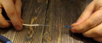
It would seem that it could be simpler than simply twisting the two ends of the wiring and insulating them. This method is only suitable for conductors made of identical metals. Simply twisting aluminum and copper wire together is extremely dangerous. It will last for some time, but will quickly cause a short circuit or even a fire.
Twisted tinned copper wire
It is believed that if a copper conductor is tinned, its direct twisting with aluminum becomes possible. Opinions on this matter vary and most of them say that to connect copper wire to aluminum in this way. But there are still risks. The rules for tinning are simple and reliable only at first glance. Over time, the protective layer may begin to deteriorate, and it is almost impossible to control this process. better this method or use it only in the most extreme cases and for a short period of time.
Main grounding bus - purpose, device and requirements for it
The definition and basic requirements for the main grounding bus are specified in the main governing documents - the Rules for the Construction of Electrical Installations (in the current 7th edition - PUE 1.7.119. - 1.7.120.) and the Code of Rules (SP 437.1325800.2018 “Low-voltage electrical installations of buildings and structures Rules for designing protection against electric shock, Chapter 9).
There are no particular contradictions between them - they are both based on the current GOST. But for a person who seriously intends to get into electrical engineering, it is better to study both documents - each has its own “rational grain”.
Purpose of the main grounding bus
So, the main grounding bus is an integral element of the electrical installation design, part of its grounding device. Its main purpose is the correct electrical connection of grounding and protective wires.
The following can be connected to it (depending on the characteristics of the general circuit):
- The main grounding of the object is through the grounding conductor.
- Protective conductor - through it, the GZSh can be connected to the protective bus of the input distribution device (IDU).
- Protective and functional grounding and potential equalization conductors.
- Conductors (jumpers) that split the combined protective and neutral conductor (PEN) into the working zero N and the protective circuit PE - in separate grounding systems.
We’ll talk more about the nuances of connecting certain conductors another time.
Design and material for manufacturing GZSh
Structurally, the main grounding bus is usually a metal strip of a certain cross-section on which connections for wires are provided. Most often these are threaded (screw or bolt) connectors. Protection against loosening of the threaded connection must be provided - using spring washers or groovers.
An example of a factory-produced main grounding bus - with bolted conductors.
The dimensions and number of contacts are determined by the characteristics of the specific object on which the grounding system is installed. For each of the connected wires, a separate contact must be provided - so that there is the possibility of individual connection and disconnection of one or another conductor. In this case, connection or disconnection must be possible only with the use of a tool.
The material for manufacturing the GZSh is predominantly copper (literally, as in the PUE “should, as a rule, be copper...”). However, the use of steel tires of adequate cross-section is also permitted. But at the same time, the steel product must necessarily have a metal anti-corrosion coating that ensures reliable electrical contact.
Exactly the same tire (as in the picture above), but made of galvanized steel. It’s not prohibited, but it’s better to install copper...
Expert opinion: Afanasyev E.V.
Chief editor of the Stroyday.ru project. Engineer.
It is best, of course, to use copper, especially when it comes to closed ASUs. Yes, it is somewhat more expensive, but it is reliable and durable. In addition, according to the experience of many electrical specialists, copper mains will never raise unnecessary questions from commissions checking the condition of electrical equipment. And steel ones sometimes lead them to some displeasure - there is something to “attach” to, where to look for shortcomings.
But what is strictly prohibited is the use of aluminum strips or profiles as tires.
Installation location of the main grounding bus
The PUE rules determine that the main switch for electrical installations with voltages up to 1 kV must be located inside the input device, or a separate installation is practiced near the ASU, but subject to certain requirements. These include mandatory restriction of access to the main power plant for all outsiders, except for trained specialists engaged in servicing the electrical installation. At the same time, its location should not create obstacles for installation, preventive, repair and restoration work. That is, comfortable conditions must be created for the craftsmen, without any interference.
In particular, separate installation of the bus is recommended in places accessible only to qualified personnel - this, for example, could be a locked switchboard room in an apartment building.
An example of an open installation of the main grounding bus on the wall of a room. Please note: all wires connected to it are marked.
If the tire has to be installed in places where it is impossible to guarantee access (for example, the common basement of a building or the entrance of a residential building), then it must be locked in a box or cabinet that can be locked with a key.
It is interesting that the Code of Rules, when interpreting the location of the tire, directly indicates a preference for its separate installation near the ASU. And placement inside the switchgear is considered acceptable.
It happens that several power lines are connected to one building, including from various substations. With this option, each input (ASU) has its own GZSh. And if the building has built-in substations, then the main grounding buses should be near each of them. But in any case, during installation, all buses must be interconnected by a protective potential equalization conductor. The cross-section of this conductor must be at least half the cross-section of the PE or PEN wire of the most powerful incoming (or outgoing from the built-in substation) lines.
Often, if there are several inputs designed for one load (for example, the main and backup power lines with switching by an automatic transfer system (ATS)), it is allowed to use one main grounding bus made of an extended metal (steel or copper) strip. Sometimes this bus can even be looped around the perimeter of the building (room).
The main grounding bus, made in the form of an extended steel strip on the wall of the room - the length can be up to complete closure. It is allowed to connect several input devices to this, but only if they are designed for equal load.
Naturally, this approach is only possible in the cases already mentioned above - when the possibility of access by unauthorized persons is completely excluded.
Another interesting nuance.
In the PUE, when considering the location of the main grounding bus, it is said that in the case when the main grounding bus is placed inside the input device, then the PE protective bus takes over its function.
The joint venture has a slightly different interpretation on this matter. It is noted there that with the help of the GZH, an electrical connection must be ensured between third-party conductive elements of the building and open conductive elements of the electrical installation of the building. And for this purpose, the ASU (VU) protective bus is connected by a PE protective conductor to the GZSh. Well, then all PE conductors of all distribution and final circuits must be connected to the PE protective bus.
It must be assumed that both options are acceptable.
The GZSh, which also acts as a PE protective bus, is located in the switchgear. PUE recommends this option, and it is really convenient.
Often, a separate lockable cabinet is provided for the main protective bus - where it cannot be located inside the ASU due to the required large dimensions, but where it is not possible to guarantee restriction of access by unauthorized persons.
Separate lockable box for the main ground bus.
A wire from the grounding device, from the input line, is laid into this box, and PE conductors diverge from the main shield to distribution boards and potential equalization systems.
International grounding sign
The appropriate grounding symbol must be marked on the box (box).
Dimensions of the main grounding bus
As we have already seen, the length of the main ground bus is not particularly adjustable. In fact, it can even completely loop around a building or room if necessary.
But in terms of width and thickness, and ultimately in terms of cross-sectional area, there are quite strict requirements. The whole point is that the bus must provide the required minimum conductivity.
The PUE states that the cross-sectional area of the bus should not be less than the cross-section of the PE or PEN conductor of the incoming supply line.
Everything seems simple, but there are nuances. In particular, power lines can be either copper or aluminum. Aluminum, by the way, is the most common, due to the lower cost of materials. And the tire, as we remember, is either copper or steel. That is, a simple geometric conversion of the area of a rectangle into the area of a circle will not work here. It is necessary to compare sections precisely according to their current-carrying ability.
There is a special calculation method that includes several rather cumbersome formulas. It will be easier to select the optimal, sufficient bus cross-section using the tables of maximum continuous currents proposed below for aluminum and copper wires of various cross-sections, designs and installation methods.
Table 1. Permissible long-term currents in the conductors of aluminum insulated cables and wires
| Conductor cross-section, mm2 | Current, A, for cables | ||||
| single-core | two-wire | three-wire | |||
| when laying | |||||
| in the air | in the air | in the ground | in the air | in the ground | |
| 2,5 | 23 | 21 | 34 | 19 | 29 |
| 4 | 31 | 29 | 42 | 27 | 38 |
| 6 | 30 | 30 | 55 | 32 | 46 |
| 10 | 60 | 55 | 80 | 42 | 70 |
| 16 | 75 | 70 | 105 | 60 | 90 |
| 25 | 105 | 90 | 135 | 75 | 115 |
| 35 | 130 | 105 | 160 | 90 | 140 |
| 50 | 165 | 135 | 205 | 110 | 175 |
| 70 | 210 | 165 | 245 | 140 | 210 |
| 95 | 250 | 200 | 295 | 170 | 255 |
| 120 | 295 | 230 | 340 | 200 | 295 |
| 150 | 340 | 270 | 390 | 235 | 335 |
| 185 | 390 | 310 | 440 | 270 | 385 |
| 240 | 465 | — | — | — | — |
Note. Permissible continuous currents for four-core aluminum cables with plastic insulation for voltages up to 1 kV can be selected from the table as for three-core cables, but with a coefficient of 0.92.
It is enough to find out what material and what cross-section the PE or PEN conductor is made of in order to assess its current capabilities.
This value will serve as an input to the second table, where everything is the same, but for copper wires and cables.
Table 2. Permissible long-term currents in the conductors of copper insulated cables and wires
| Conductor cross-section, mm² | Current, A, for copper | ||||
| single-core | two-wire | three-wire | |||
| when laying | |||||
| in the air | in the air | in the ground | in the air | in the ground | |
| 1.5 | 23 | 19 | 33 | 19 | 27 |
| 2.5 | 30 | 27 | 44 | 25 | 38 |
| 4 | 41 | 38 | 55 | 35 | 49 |
| 6 | 50 | 50 | 70 | 42 | 60 |
| 10 | 80 | 70 | 105 | 55 | 90 |
| 16 | 100 | 90 | 135 | 75 | 115 |
| 25 | 140 | 115 | 175 | 95 | 150 |
| 35 | 170 | 140 | 210 | 120 | 180 |
| 50 | 215 | 175 | 265 | 145 | 225 |
| 70 | 270 | 215 | 320 | 180 | 275 |
| 95 | 325 | 260 | 385 | 220 | 330 |
| 120 | 385 | 300 | 445 | 260 | 385 |
| 150 | 440 | 350 | 505 | 305 | 435 |
| 185 | 510 | 405 | 570 | 350 | 500 |
| 240 | 605 | — | — | — | — |
Note: The currents in this table apply to wires and cables with and without a neutral core.
Let's give an example.
The incoming line to the house is made of four-core aluminum cable brand APVBBShp(G) 4×150-1. The cable connection is underground.
Aluminum four-core cable APVBbShp(G) 4×150-1 is often used for entry into a building
We enter Table No. 1 and see that for such a cross-section (150 mm²) for a three-core underground cable, the permissible long-term current is 335 amperes. Since we have a four-core cable, we use the coefficient shown in the note of 0.92, and we get 308 amperes.
We find the closest (increasingly) current value in table No. 2 - and in the same place, in the column of three-core underground cables. This value is 330, corresponding to a copper cable cross-section of 95 mm². Therefore, this is the minimum cross-section of the main grounding bus.
Calculating the cross-sectional area of a tire and choosing the right one is not difficult, especially if you have before your eyes the standard sizes of industrially produced products.
Table 3. Standard cross-sectional sizes of manufactured conductive copper busbars
| 3 mm thick | 4 mm thick | 5 mm thick | 6 mm thick | 8 mm thick | 10mm thick |
| 3×15 | 4×30 | 5×20 | 6×30 | 8×30 | 10×10 |
| 3×20 | 4×40 | 5×25 | 6×50 | 8×40 | 10×20 |
| 3×25 | 4×50 | 5×30 | 6×60 | 8×50 | 10×30 |
| ZxZO | 4×60 | 5×40 | 6×80 | 8×60 | 10×40 |
| 3×40 | 4×80 | 5×50 | 6×100 | 8×80 | 10×50 |
| 3×50 | 5×60 | 8×100 | 10×60 | ||
| 3×60 | 5×80 | 10×80 | |||
| 3×80 | 5×100 | 10×100 | |||
| 5×125 | 10×120 | ||||
| 10×160 |
For example, for the main bus in our example, copper busbars 3x40 or more, 4x30 or more, 5x20 or more are suitable. A thickness of 6 mm and above is unlikely to be a reasonable solution - a waste of money.
When choosing bus sizes, one more point should be taken into account - the dimensions of the screw or bolt connections and the contacts connected to them. It is unacceptable if the heads of screws, bolts, nuts and even washers protrude beyond the surface of the metal strip, no matter whether from below or above, left or right. They must be adjacent to the tire with their entire area. Exactly the same requirement applies to terminal lugs - they must “participate” in contact with the entire area of their working surface.
Each connection "socket" on the main ground bus should only be used for one contact. Contact parts (washers, bolts, nuts, terminal lugs of conductors) must not extend their working plane beyond the bus surface.
There is an easier way to select the cross-section of a copper busbar. Calculations have already been carried out, even more accurate than suggested above, and the results are listed in the table. It indicates the most common standard bus sections and the maximum currents that it can withstand for a long time.
Please note that there are two columns with current indicators - for alternating (AC) and direct (DC). True, for tires of small and medium sections these parameters are almost the same.
Just for reference purposes, the weight of the tire with a length of 1 meter and 4 meters is also indicated.
Table No. 4. Standard cross-sections of copper busbars and maximum continuous currents that they can withstand
| Tire section, mm² | Allowable current | Tire weight, kg | ||
| AC (variable) | DC (constant) | for 1 meter | for 4 meters | |
| Copper bus 15*3 | 210 | 210 | 0,4 | 1,61 |
| Copper busbar 20×3 | 275 | 275 | 0,54 | 2,14 |
| Copper busbar 25×3 | 340 | 340 | 0,67 | 2,68 |
| Copper busbar 30×4 | 475 | 475 | 1,07 | 4,29 |
| Copper busbar 40×4 | 625 | 625 | 1,43 | 5.71 |
| Copper busbar 40×5 | 700 | 705 | 1/79 | 7,14 |
| Copper busbar 50×5 | 860 | 870 | 2,23 | 8,93 |
| Copper busbar 50×6 | 955 | 960 | 2,68 | 10,72 |
| Copper busbar 60×6 | 1125 | 1145 | 3,22 | 12,86 |
| Copper busbar 60×8 | 1320 | 1345 | 4,29 | 17,14 |
| Copper busbar 60×10 | 1475 | 1525 | 5,36 | 21,43 |
| Copper busbar 80×6 | 1480 | 1510 | 4,29 | 17,14 |
| Copper busbar 80×8 | 1690 | 1755 | 5,72 | 22,86 |
| Copper busbar 80×10 | 1900 | 1990 | 7,15 | 28,58 |
| Copper busbar 100×6 | 1810 | 1875 | 5,36 | 21,43 |
| Copper busbar 100×8 | 2080 | 2180 | 7,15 | 28,58 |
| Copper busbar 100×10 | 2310 | 2470 | 8,93 | 35,72 |
| Copper busbar 120×8 | 2400 | 2600 | 8,57 | 34,29 |
| Copper busbar 120×10 | 2650 | 2950 | 10,72 | 42,86 |
If, in order to save money, or if it is impossible to purchase a copper busbar, it is decided to use a steel one, then its cross-sectional size can be taken from the following table.
Table No. 5 Standard cross-sections of steel busbars and maximum continuous currents that they can withstand
| Standard cross-sectional dimensions of steel busbars, mm | Permissible maximum current, A |
| 16×2,5 | 55/70 |
| 20×2,5 | 60/90 |
| 25 x 2.5 | 75/110 |
| 20×3 | 65/100 |
| 25×3 | 80/120 |
| 30×3 | 95/140 |
| 40×3 | 125/190 |
| 50×3 | 155/230 |
| 60×3 | 185/280 |
| 70×3 | 215/320 |
| 75×3 | 230/345 |
| 80×3 | 245/365 |
| 90×3 | 275/410 |
| 100×3 | 305/460 |
| 20×4 | 70/115 |
| 22×4 | 75/125 |
| 25×4 | 85/140 |
| 30×4 | 100/165 |
| 40×4 | 130/220 |
| 50×4 | 165/270 |
| 60×4 | 195/325 |
| 70×4 | 225/375 |
| 80×4 | 260/430 |
| 90×4 | 290/480 |
| 100×4 | 325/535 |
In the “maximum current” column, the values for alternating and direct current are separated by a slash.
* * * * * * *
Sometimes it is impossible to calculate the bus size based on the PE or PEN cross-section of the input line conductor - in some grounding systems they are simply not available. What should I do?
This question is answered in the guidelines for the installation of electrical networks. In particular, Technical Circular No. 6/2004 “On the implementation of the basic potential equalization system at the entrance to the building” is in force. And as we have already said, the BPCS is always connected directly to the main ground bus.
According to this Circular, the cross-sectional area of the main shield can be assessed using the cross-section of the phase conductor. Nothing complicated - just use the table:
Table No. 6 Determination of the minimum cross-section of the main grounding bus from the cross-section of the phase conductor
| Phase conductor cross-section S | Minimum permissible cross-section of the main grounding or PE bus |
| up to 16 mm² inclusive | equals S |
| from 16 mm² to 35 mm² inclusive | 16 mm² |
| from 35 mm² to 400 mm² inclusive | 0.5S |
| from 400 mm² to 800 mm² inclusive | 200 mm² |
| over 800 mm² | 0.25S |
Expert opinion: Afanasyev E.V.
Chief editor of the Stroyday.ru project. Engineer.
There is some contradiction - if you follow the recommendations of the Circular, the tire may turn out to be smaller than according to the requirements of the PUE. On the one hand, this is beneficial purely financially - purchasing a tire will cost less. But on the other hand, who knows what guidance document the inspector will refer to when accepting the finished electrical object.
So, it is probably better to follow the recommendations of the PUE - with this approach, the tire dimensions are guaranteed to fall under the rules formulated by the Circular.
* * * * * * *
Now would be a good time to move on, in fact, to the rules for installing the main grounding bus, to the relative positions of the wires connected to it, to the nuances of its use in the main and additional potential equalization systems, PE protective grounding, and even about the possible connection with the lightning protection circuit of the building. Nevertheless, for now we will limit ourselves to the information already presented, since without the necessary knowledge, for example, about the various grounding systems in practice for power transmission to ASU, this will be an empty conversation. A detailed acquaintance with grounding systems, as well as with potential equalization systems, necessarily requires its own detailed analysis. And these articles, which must appear on the pages of our portal, can be considered a logical continuation of this publication.
Finally, there is one more important nuance, without which high-quality electrical installation is impossible, including input devices with a main grounding bus. We are talking about the color coding of the conductors used in the circuit. Insulation colors are not taken from personal preference - there are international standards that must be adhered to.
But how much easier is the subsequent acquaintance with such mounted installations - especially if the master electrician was not lazy, but also provided the conductors with appropriate labels that clearly determine the purpose of a particular wire.
The following video explains color coding well:
The simplest and most reliable connection between aluminum and copper wires
How to safely and correctly connect an aluminum conductor to copper and which adapter from one metal to another - on this matter, every electrical installation specialist has his own opinion, developed as a result of an analysis of work and personal experience. But most of them say that the simplest, most modern and safest method to connect copper and aluminum wiring is using WAGO terminal blocks with paste. They are safe for wires, and installation with them takes a minimum of time. In this case, the cheapest way is to use a bolt with a nut and washers to align the cables.
What methods to use to make the transition from aluminum to copper , everyone decides for himself.
Video
There are many videos showing how to connect copper and aluminum into a single network without compromising safety . They are useful for both beginners and experienced professionals who are ready to learn from other people’s experiences and learn outside opinions.
Recommended viewing:
- Where are electrical circuit diagrams used...
- All about current strength in physics
- How and with what to charge a li-ion (Li-po) battery?…
- How to make a TV antenna with your own hands
- How to check battery charge with a multimeter
- How to properly install HDM on the ceiling?
8+
Connection quality
In most of the previously discussed cases, rigid fastening of conductors stripped of the insulating layer is used. However, when joining copper and aluminum, one important technological nuance must be taken into account: aluminum, under the influence of load, acquires plasticity, as experts say, it begins to “flow” . As a result of this process, the connection weakens, and therefore the bolts need to be tightened regularly. If you do not tighten the bolts in time, the terminal may simply catch fire due to severe overheating.