Why contact connections must be made correctly
First of all, let's look at what the requirements for high-quality contact connections are related to.
It is not without reason that clause 2.1.21 of the PUE separately stipulates methods for connecting wires, and allows only screw or bolt clamps, crimping, welding or soldering. Poor contact is the main cause of fires
This is primarily due to the fact that these types of connections can provide the proper level of durability and reliability of the connection
After all, any electrician will tell you that more than 90% of all damage occurs at contact connections, and that is why so much attention is paid to them.
After all, what is a poor-quality contact connection is a connection that has a high contact resistance. And since we have resistance, this means heating.
Dependence of resistance on conductor temperature
- As we remember from the physics course, any conductor in a heated state has greater resistance than a conductor with a lower temperature. Therefore, an avalanche-like process results. A poor-quality contact connection causes the conductor to heat up and its resistance increases even more. As a result, it heats up even more until it reaches the point where it simply melts.
- As a result, our main task is to ensure minimum resistance between the two conductors being connected. This is achieved by ensuring the proper area of contact between the two conductors, as well as by ensuring the maximum possible contact between them.
- Let's immediately look at why we will not consider the question of how to twist single-core wires or their multi-core counterparts. Indeed, with the right approach, and through twisting, it is possible to ensure a sufficient area of contact and compression of the conductors with each other.
Twisting is prohibited
The fact is that in any case, the contact connection will be subject to temperature influences. That is, it will heat up and cool down. And as we know, heating leads to expansion of materials, and cooling, accordingly, to contraction. As a result, our contact connection, which is not fixed by any third element, can quickly become of insufficient quality.
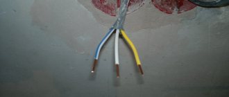
Connection of solid and stranded wires
There are times when it becomes necessary to connect single-core and stranded wires together
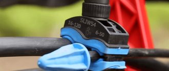
In this case, you immediately need to pay attention to the materials from which they are made, since copper and aluminum will inevitably enter into a chemical reaction over time, oxidation and disruption of electrical contact will occur, which will lead to heating and an emergency situation. The connection of an aluminum wire with a copper wire should be done through a bolted or terminal connection, using any of the methods of fixing a stranded wire described above and used to form a monolithic structure
If you need to connect a single-core and stranded copper wire, this can be done in several ways:
- Twist as shown in the photo below.
- Twisting followed by soldering.
- Using a terminal block.
- Putting the ends under the bolt and pressing them.
After any connection is made, it is necessary to carefully insulate this place with insulating tape or heat shrink.
But since twisting is prohibited according to Chapter 2.1 of the PUE, clause 2.1.21, this method is suitable for a temporary connection. It is better to make rings, tin them and connect them with a bolt, or use lugs with ring terminals. You can also use WAGO type terminal blocks.
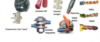
What is the best way to reliably connect two cables together?
Methods of connecting cables that require equipment and skills in the field of electrical engineering:
Simple connection methods that do not require tools or knowledge:
- connection using terminal blocks;
- spring clamps;
- PPE caps;
- bolted connection.
The choice of connection method depends on the characteristics of the wires. It is necessary to take into account the type and material of the core, the number of wires, and operating conditions.
With soldering
Soldering is a common method of connecting cables. To work you need a soldering iron, rosin, solder and sandpaper. How to connect wires by soldering:
- stripping of insulation;
- cleaning from oxides using sandpaper;
- the conductors need to be tinned - rosin is placed on the wire, it is heated with a soldering iron until the wire is covered with rosin;
- the conductors are assembled together, bubbling rosin must be applied to them and heated until the solder spreads;
- The soldering area is cooled.
The complexity of the process lies in the availability of professional skills. Do not overheat the solder area or twist it when heating, otherwise the insulation may melt
It is important to ensure high-quality and reliable contact of the wires. Soldering is used in low-current electrics
No soldering
Wires are connected without soldering using special connecting elements. It is also possible to connect the wires by twisting. Twisting is the simplest method that does not require equipment, but this method is also the most unreliable.
Copper
Copper wire can be connected using terminal blocks, Wago clamps (necessarily using special paste), using a bolt, or soldering.
Aluminum
Aluminum wires can also be connected using any method, but with some special features. When connecting, the metal must be manually stripped of insulation.
Types of electrical wire connections
There are about a dozen ways to connect wires. In general, they can be divided into two groups: those that require special equipment or specific skills and those that can be successfully used by any home craftsman - they do not require any special skills.
Don't know how to connect two wires? Choose the most suitable method
The first group includes:
- Soldering. When connecting wires of small diameter in the amount of 2-3 pieces, this is a very reliable method. True, it requires a soldering iron and some skills in using it.
- Welding. You need a welding machine and special electrodes. But the contact is reliable - the conductors are fused into a monolith.
- Crimping with sleeves. You need sleeves and special pliers. The sleeves are selected according to certain rules that you need to know. The connection is reliable, but it will have to be cut to re-seal.
All these methods of connecting wires are performed mainly by specialists. If you have skills in handling a soldering iron or welding machine, after practicing on unnecessary scraps, you can make them yourself.
Some methods of connecting wires are more popular, others less so.
Methods of connecting wires that do not require any specific skills are becoming increasingly popular. Their advantage is quick installation and reliable connection. Disadvantage - you need “connectors” - terminal blocks, clamps, bolts. Some of them cost quite a lot of money (Wago terminal blocks, for example), although there are also inexpensive options - screw terminal blocks.
So here are ways to connect wires that are easy to implement:
- Terminal blocks. They are characterized by ease of installation and low price. To connect the wires, you only need a screwdriver. Disadvantage: The bolted connection may become loose over time.
- Wago type spring clamps. Very simple installation, easy but quite high cost. Another drawback is the large number of fakes.
- PPE caps. Quick installation, good contact, can be installed several times. The disadvantage is that there are many low quality products.
- Bolted connection. Reliable connection at low cost. Typically used when converting from aluminum to copper. Disadvantage: bulky and inconvenient.
There are two opposing opinions among professionals. Some believe that new methods of connecting wires - clamps - are the best solution, as they speed up installation without compromising the quality of the connection. Others say that the springs will eventually weaken and contact will deteriorate. In this matter, the choice is yours.
What is a junction box
From the electrical panel, the wires disperse throughout the rooms in the house or apartment. Each room, as a rule, has more than one connection point: there are several sockets and a switch. To standardize the methods of connecting wires and collect them in one place, distribution boxes are used (they are also sometimes called branch boxes or junction boxes). They contain cables from all connected devices, the connection of which occurs inside the hollow housing.
In order not to look for wiring during the next repair, it is laid according to certain rules that are prescribed in the PUE - Rules for the Construction of Electrical Installations.
Electrical wiring rules
One recommendation is to carry out all connections and branch wires in the junction box. Therefore, the wires are run along the top of the wall, at a distance of 15 cm from the ceiling level. Having reached the branch point, the cable is lowered vertically down. A distribution box is installed at the branch point. It is where all the wires are connected according to the required circuit.
According to the type of installation, junction boxes are either internal (for hidden installation) or external. Under the internal ones, a hole is made in the wall into which the box is built. With this installation, the cover is flush with the finishing material. Sometimes during the renovation process it is covered with finishing materials. However, such installation is not always possible: the thickness of the walls or finishing does not allow it. Then a box for external mounting is used, which is attached directly to the wall surface.
Some forms of junction boxes
The shape of the junction box can be round or rectangular. There are usually four conclusions, but there may be more. The terminals have threads or fittings to which it is convenient to attach a corrugated hose. After all, it is more convenient to lay wires in a corrugated hose or plastic pipe. In this case, replacing the damaged cable will be very simple. First, disconnect it in the distribution box, then from the consumer (socket or switch), pull it and pull it out. Tighten a new one in its place. If you lay it the old fashioned way - in a groove, which is then covered with plaster - you will have to drill into the wall to replace the cable. So this is the recommendation of the PUE, which is definitely worth listening to.
What do distribution boxes generally provide:
- Increased maintainability of the power supply system. Since all connections are accessible, it is easy to determine the area of damage. If the conductors are laid in cable channels (corrugated hoses or pipes), replacing the damaged section will be easy.
- Most electrical problems arise in the connections, and with this installation option they can be inspected periodically.
- Installing distribution boxes increases the level of fire safety: all potentially dangerous places are located in certain places.
- Requires less money and labor than laying cables to each outlet.
Insulation of electrical connections
All parts of electrical wiring must be insulated to prevent accidental contact of parts of conductive elements with each other and with the human body. The choice of insulating materials depends on the operating conditions of the electrical circuit. For most cases, insulation from heat-shrinkable or vinyl tubing, as well as special insulating tape, is sufficient.
If the joint can be exposed to high temperatures, then varnished cloth and fabric insulating tape are used for insulation, which can withstand prolonged exposure to temperatures up to 100 °C.
The operation of electrical wiring depends on many factors, not least of which is the correct electrical installation. Reliable connection of wires and correct connection of electrical network elements allow you to avoid the occurrence of places with poor contact and, as a result, local overheating and electrical wiring breaks.
The wire connection method used largely depends on the maximum load and operating conditions of the wiring. In damp rooms and outdoors, you should give preference to copper wiring with soldered connections, as it is less sensitive to oxidation.
Vlad Taranenko, rmnt.ru
Twisting wires
The simplest way to connect two or more conductors is the so-called twisting. This connection is made using various techniques, of which simple twisting is intuitive.
The connection of two flexible stranded wires in the form of a simple parallel twist provides reliable contact between the two wires, but the twist does not tolerate vibration and the force applied to breaking.
Using parallel twisting, you can connect solid and stranded copper wires; thanks to the additional bending of the solid wire, this connection is more reliable than when connecting two stranded wires.
A similar method is used to connect aluminum wires of different sections.
The use of parallel twisting makes it possible to provide electrical contact simultaneously between two or more wires.
A simple twist can be used to electrically connect an additional wire to the main wiring line without breaking it.
The same joining method can be used to join together a solid wire drop to a flexible or solid main wire.
To connect two wires together, they can be sequentially twisted, for which each connected wire is “wound” around the other.
This method of connecting wires allows for optimal contact and reliability of the connection, but only for two wires.
The connection of rigid wires to each other can be done using bandage twisting. To do this, the wires to be connected are applied parallel to each other, after which they are fixed in this position using a softer wire, which is laid tightly on the bare surface of the wires.
The tighter the twisting or winding is done, the better the electrical contact between the conductors will be.
Using a bandage, you can connect two or more conductors or organize bends.
To improve fixation, you can additionally bend the monolithic wire, thereby fixing the bandage.
During installation, it is necessary to ensure that the twisted parts of the conductors are completely cleared of insulation; the copper or aluminum surface of the conductors must be clean and free of traces of oxidation. If necessary, before twisting, the surface of the connected wires must be cleaned with a knife or sandpaper. To increase twisting density, and, as a result, electrical contact between conductors, twisting can be done using pliers
It is important to remember the main installation rule - you cannot directly connect copper and aluminum wiring
Connection of flexible and rigid wires
Connection of flexible and rigid wires
Usually, conductors of the same type are connected. But sometimes a connection between a flexible and a rigid wire is required, which is carried out in compliance with some nuances.
First, cut the cable so that its end is tapered. The rigid wire needs to be melted and a loop made at its end. A thin wire is passed through the loop made and wrapped around the rigid cable. The resulting connection must be treated with solder and reliably insulated. A similar method is suitable for aluminum conductors.
A quick connection with big consequences
We often don’t think about the consequences of such a “simplification”. Meanwhile, an unreliable contact will fail at the most inopportune moment; the power supply to consumers/power receivers can always be cut off. Voltage “surges” cause breakdown of the elements of the power cascades of complex SBT household appliances. Even special protection devices used in the most “sophisticated” models of foreign manufacturers cannot save you from breakdown.
The induction of short electromagnetic pulses with a voltage of several thousand volts onto the electronic filling causes “harmless” sparking at the joints. At the same time, the standard protection equipment with which apartments are now equipped (RCDs, circuit breakers, fuses) do not “see” such short low-current pulses, so they simply do not trigger them, and we do not accept installing special devices for this. Uninterruptible power supplies for computers also did not become a panacea for transient impulses. The occurrence of “poke” causes malfunctions in the operation of electronic equipment and computer equipment, leading to failure of electrical components and expensive functional modules. Overheating at the site of a poor connection leads to even more catastrophic consequences; when current passes, the weakened connecting node becomes red-hot. This often causes fires and fires, causing enormous damage to the owners of the premises. Statistics show that 90% of all electrical wiring faults occur due to twists and poor contact connections of conductors. In turn, the very malfunction of electrical wiring and equipment, according to the Ministry of Emergency Situations, is the cause of one third of the fires that occur in Russia.
However, it so happened historically that several decades ago, in conditions of a shortage of electrical accessories/copper conductors, twisting aluminum wires was considered the main method used in electrical installation work. Twisting as a connection can be used in electrical engineering when carrying out repair and restoration work.
Conclusion
Modern installation methods make it possible to make high-quality contact connections of single-core and multi-core wires. The choice of the optimal switching method depends on the conditions of installation work and operating conditions of the wiring.
Sources
- https://aqua-rmnt.com/ehlektrosnabzhenie/kak-soedinit-mnogozhilnyie-provoda-mezhdu-soboy.html
- https://Elektrik-a.su/energii/soedineniya/kak-soedinit-mnogozhilnyj-i-odnozhilnyj-provod-253
- https://elektrika.expert/provodka/soedinenie-provodov.html
- https://VseOToke.ru/montazh/esli-nuzhno-sostykovat-odnozhilnyj-provod-s-mnogozhilnym
- https://elektrik-sam.ru/jelektroprovodka/3618-kak-podkljuchit-mnogozhilnyj-provod-ili-soedinit-ego-s-odnozhilnym.html
- https://StrojDvor.ru/elektrosnabzhenie/kak-soedinit-odnozhilnyj-i-mnogozhilnyj-mednyj-provod/
- https://www.akruks.net/article/montazh/p489-soedinenie_mnogozhiljnogo_i_odnozhiljnogo_provoda/
[collapse]
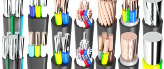
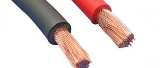
Difference between cable and wire
Difference between cable and wire
A cable is a plastic or rubber line that places several insulated conductors inside. The conductors are combined into a single system for ease of installation and operation, and protection from external influences. A special cable can be easily distinguished by the presence of an armored casing that prevents damage due to mechanical action.
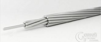
A wire is a stranded or single-core carrier, equipped with light tubular insulation or represented by a hollow metal rod with a core cross-section of 1.5 mm.
The differences between cables and wires are in the number of cores, type of insulation, marking and purpose. Due to the double insulation of the current-carrying conductors, the cable passes large currents and voltages relative to the wire. The difference is hundreds of kilovolts in favor of the cable.
Outer shell
According to GOST 15845-80, a wire is one conductor, a cable is two or more insulated cores combined in additional insulation. If there is no protective sheath on two or more metal rods, it is classified as a wire.
Explanation of meanings
Cable and wire markings differ in letters and numbers.
Wire names contain the following meanings:
- the letter "A" in front indicates that it is aluminum wire;
- “P” – copper wire;
- “PP” – 2 or 3 flat copper conductors;
- the following values: “P” – polyethylene insulation, “P” – rubber, “B” – vinyl, “L” – cotton braid;
- “N” – additional protection with non-flammable nairite, “B” – vinyl;
- “G” – the letter makes the difference in marking, thanks to the flexible current-carrying core;
- “TO” – anti-rot coating.
Power cable marking
When marking cables, GOST establishes the following procedure:
- Core type. “A” – aluminum, absence of letter – copper.
- Purpose. “K” – control, “KG” – with increased flexibility.
- Protection. “P” – polyethylene, “V” – vinyl, “R” – rubber, “NG” – non-flammable and “F” – fluorolone shell.
- Armor or external covering. “A” – aluminum, “C” – lead, “P” – polymer, “B” – vinyl, “P” – rubber, “O” – coating of all phases, “Pv” – vulcanized plastic.
- Protection. “B” – anti-corrosion armor, “Bn” – non-flammable armor, “2g” – double PVC tape, “Shv” – vinyl hose, “Shp” – polymer hose, “Shps” – self-extinguishing polymer hose.
Scope of use
Category 5 cable
Reliable protection against mechanical and aggressive action, extended service life, rated voltage are the main features of the cable, which should be distinguished from wire when installed in special conditions. Powerful insulated systems are suitable for laying electrical networks under water, underground, in mines, in areas of high fire hazard and corrosion activity.
According to the PUE (electrical installation rules), the cable is divided into 5 categories:
- Power ones are designed for transmitting electricity; they are installed stationary or when connecting mobile consumers.
- Installation conductors are used when laying devices between devices. They cope well with elevated temperatures and voltages of 500 V.
- Communication devices are found in alarm and wired communication systems.
- Control lines are well proven for connecting control and lighting circuits in 600 V electrical equipment.
- RF and optical media transmit energy and signals at specified radio frequencies or optical wavelengths.
Wire PUGNP
According to the area of application, wires are classified into installation, power, and installation groups. The former are used for flexible or fixed wiring in distribution boards, radio and electronic equipment manufacturing. Power options are part of electrical networks; installation wires are applicable when connecting installations and power transmission systems inside and outside buildings.
- For stationary installation in enclosed spaces, suitable wires are PUGNP, PUNP, APUNP, PVS.
- Installation and mounting products - PV-1, PV-3, APV, MKESH - are laid in pipes, construction voids, cable trays and under plaster.
- In places that require increased heat resistance, PNSV wires are used.
- For overhead lines, SIP-2, SIP-3, SIP-4 are suitable
- Low-current communications – PRPPM, TPPep, TRP.
Life time
The average service life of a cable is 30 years, wires - from 6 to 15 years. The duration of operation is determined by the presence/absence of two or more insulations and an armored shell.
How to weld twisted wires: what is important to consider
This method is based on creating local heating of the end of the twist to the temperature of the metal melt, followed by its solidification in the form of a contact ball.
The work can be done with a homemade step-down transformer with a voltage of about 24 volts and a power of 1 kilowatt.
But it is better to use an inverter that produces direct current. To create an arc, a carbon electrode is used, which touches the welding site. It can be replaced with graphite.
The second contact of the circuit is formed by crimping the opposite part of the twist with pliers near the insulation. Their wide jaws serve as a cooling radiator, removing heat from the dielectric layer, protecting it from overheating and damage.
The current strength is about 30-80 amperes and the duration of its flow is about a second, which is selected experimentally depending on the design of the welding machine, the chemical composition and thickness of the cores.
When working at heights near the ceiling, it is convenient to place the wires down.
At the end of the weld, a drop-shaped alloy is formed in the shape of a contact ball.
To ensure reliable contact, you first need to practice on a control sample. A small current will not heat the joint well, but an excessive current will transfer excessive temperature to the insulation layer and burn the metal.
Evaluate the test welding both for mechanical strength and for the created weld structure.
What to pay attention to
The vertical arrangement of the twist during welding allows the melt to better fill the space between the copper wires, giving the drop of metal the shape of a sphere.
You must work in protective gloves, use a welder's mask to protect your eyes, and special shoes. You can easily “catch bunnies” or “catch” a drop of molten metal on clothes or shoes.
After welding one joint, it is better to wait a short time and let it cool, and then move on to processing the next one. This recommendation will prevent accidental burns.
After welding, the exposed conductors are insulated, put on a heat-shrinkable tube, and treated with an industrial hair dryer.
Then the wires are placed in a junction box and covered with a lid.
Soldering. Connecting wires by soldering.
Soldering is a method of joining metals using another, more fusible metal. Compared to welding, soldering is simpler and more affordable. It does not require expensive equipment, is less fire hazardous, and the skills needed to perform good quality soldering will require more modest skills than when making a welded joint. It should be noted that the metal surface in air is usually quickly covered with an oxide film, so it must be cleaned before soldering. But the cleaned surface can quickly oxidize again. To avoid this, chemicals are applied to the treated areas - fluxes, which increase the fluidity of the molten solder. This makes the soldering stronger.
Soldering is also the best way to terminate copper strands into a ring - the soldered ring is evenly coated with solder. In this case, all wires must completely fit into the monolithic part of the ring, and its diameter must correspond to the diameter of the screw clamp.
The process of soldering wires and cable cores consists of covering the heated ends of the connected wires with molten tin-lead solder, which after hardening provides mechanical strength and high electrical conductivity of the permanent connection. The soldering must be smooth, without pores, dirt, sagging, sharp bulges of solder, or foreign inclusions.
To solder copper conductors of small cross-sections, use solder tubes filled with rosin, or a solution of rosin in alcohol, which is applied to the joint before soldering.
To create a high-quality soldered contact connection, the wire (cable) cores must be thoroughly tinned, and then twisted and crimped. The quality of the soldered contact largely depends on correct twisting.
After soldering, the contact connection is protected by several layers of insulating tape or heat shrink tubing. Instead of insulating tape, the soldered contact connection can be protected with an insulating cap (PPE). Before this, it is advisable to coat the finished joint with a moisture-resistant varnish.
Heating of parts and solder is carried out with a special tool called a soldering iron. A prerequisite for creating a reliable connection using soldering is the same temperature of the surfaces being soldered. The ratio of the temperature of the soldering iron tip and the melting temperature is of great importance for the quality of soldering. Naturally, this can only be achieved with the help of a properly selected tool.
Soldering irons vary in design and power. To perform household electrical work, a conventional electric rod soldering iron with a power of 20-40 W is quite sufficient. It is advisable that it be equipped with a temperature regulator (with a temperature sensor) or at least a power regulator.
Experienced electricians often use an original method for soldering. In the working rod of a powerful soldering iron (at least 100 W), a hole with a diameter of 6-7 mm and a depth of 25-30 mm is drilled and filled with solder. In a heated state, such a soldering iron is a small tin bath, which allows you to quickly and efficiently solder several multi-core connections. Before soldering, a small amount of rosin is thrown into the bath, which prevents the appearance of an oxide film on the surface of the conductor. The further soldering process involves lowering the twisted connection into such an improvised bath.
Soldering
Soldering is when electrical wires are joined using molten solder. This type of connection is most suitable for copper wires. Although there are now various fluxes for aluminum, experienced electricians prefer to refrain from such soldering. But if necessary, you can use special fluxes and even solder copper and aluminum.
Positive sides
This type of connection cannot be compared with twisting; soldering is much more reliable (in terms of reliability it is second only to welding).
Using soldering, you can connect stranded and single-core wires, as well as wires of different sections.
This type of connection does not require any maintenance throughout the entire period of operation.
Soldering is considered low in cost, the only equipment you need is a soldering iron, and flux and solder are very inexpensive, and their consumption is quite negligible.
Negative sides
The disadvantages of this method include high labor intensity. Soldering requires certain preparatory work; wire strands must first be tinned before twisting. The surfaces to be soldered must be free of oxides and absolutely clean before starting work.
And of course, you need experience in using a soldering iron, that is, the person who will connect the wires using the soldering method must have a certain qualification
After all, during the soldering process it is very important to maintain the required temperature conditions. An underheated soldering iron will not heat the connection well; overheating is also unacceptable, because the flux will burn out very quickly, not having time to do its job
Soldering is a slow process, but this disadvantage is compensated by the reliability of the contact connection.
Installation
The step-by-step soldering process is as follows:
- Remove the insulation from the cores by 40-50 mm.
- Sand the bare areas of the wires until they shine using sandpaper.
- Dip a heated soldering iron into rosin and move it over the cleaned surfaces several times.
- Perform a twist.
- Bring the soldering iron tip to the solder.
- Now immediately heat the twist with solder, the tin should melt and fill the gaps between the turns.
- Thus, the entire twist is enveloped in tin, after which it is allowed to cool.
- Wipe the hardened solder with alcohol and insulate it.
Soldering wires with a soldering iron is shown in this video:
Soldering wires using a gas soldering iron:
Soldering twists by immersion in molten solder:
Safety Tips and Rules
Only craftsmen with a qualification group are allowed to weld. Persons who have skills in working with a soldering iron are also allowed to solder.
Cables may only be connected in the manner permitted for them. Do not work with damaged wiring. All exposed parts must be insulated.
You can connect the cables in different ways. The choice of connection method is determined by the material, cross-section diameter and other parameters. For electrical equipment to operate correctly, the conductors need to be connected securely. In case of unreliable contact, there is a risk of fire.
Wire Mounting Clamps
Let's move on to the second type of clamps, which are necessary when installing electrical networks. If the previously discussed options are used for switching conductors, then everything that will be presented in this chapter is used for fixing wires.
Linear tension wire clamp
All clamps that are used to secure cables and wires are divided into supporting ones (they are suspended on intermediate supports) and tension ones, which are held on anchor-type supports.
Clamps are also divided according to strength:
Clamps for linear wires are blind
- Blind - the strength of the sealing of these devices varies from 30 to 90% of the strength of aluminum wires or 10-15% of steel cables. If there is a break on one of the spans, the wire does not jump out of the clamp, but the tension from it is transferred to the support. This type is the most common when installing overhead power lines.
- Drop-out or releasing - they throw out a boat with a wire when the support garland is deflected at an angle of about 40 degrees, which ensures that there is no additional pressure on the support and a reduction in its mass. Today they are not used due to frequent cases of spontaneous ejection.
- Multi-roller - in fact, this is not quite a clamp, since the wire inside them rolls over the rollers, depending on the tension force in the adjacent spans.
- Pressed tension type clamps – This is a steel anchor in which the wire is pressed.
Wire clamp on pole
- Wedge clamp - consists of three metal parts: a base, a wedge and a pressure plate. When the wire is tensioned, it is held in place due to the high friction force. The parts wedge into each other.
In particular, the last version of the clamp can be installed with your own hands. The option shown in the photo above is used for fastening low-voltage wires and optical communication cables.
Crimping with sleeves: technology features
The installation method is based on creating tight contact between metal conductors placed inside a tube made of the same material and compressing the entire structure under a certain force with a uniform distribution of the acting load.
Good electrical contact is created due to the joint deformation of metals.
The sleeve (tube for connecting wires) is produced by industry for specific wire sizes and their quantity. They can be designed to connect cores from:
- copper;
- aluminum;
- and even copper and aluminum.
Copper sleeves (CM) can be produced with additional tinning with tin and bismuth. They are designated GML and are noted for their high resistance to corrosion.
Aluminum sleeves are designated GA. To connect copper and aluminum wires, GAM sleeves are used, and with an insulation layer they are called GSI.
Their sizes can be found in catalogs. As an example, I present the main characteristics of some GML cartridges in a small table.
The dimensions of the sleeve are specially selected for the cross-section of the switched wire. Their correct choice affects the quality of the electrical connection.
For crimping, a special tool is used: press pliers. If you work with pliers, hammers and other improvised means, the contact created will be of poor quality.
Press pliers are produced in various designs and operating principles for crimping different types of sleeves and tips.
Using the same principle, lugs for stranded wires are selected and crimped for connecting them to the terminals of electrical equipment.
This is especially true for automotive equipment, where wiring is subject to increased mechanical vibrations and electrical loads. Yes, and in the household network there is installation with flexible conductors.
As an example, retro wiring in a wooden house. Although this is not the only case.
Crimping of conductors is a rather large and complex topic, which allows you to create a high-quality connection of electrical contacts. Andrey Kulagin explains its technology well in his video. I recommend watching it.
Conclusions and useful video on the topic
To properly compress the sleeve when connecting electrical wires, you will need training and a special tool - press pliers. Detailed crimping process in the video:
Even the most expensive terminal block can turn out to be a cheap fake. The video clip demonstrates the main differences between the original Wago:
The video shows a method of bolting copper and aluminum wire:
The connection of wires using welding can be seen in the video clip:
When choosing a method for connecting electrical wires, you should focus on the feasibility of its use in a particular situation. If you need to completely replace the wiring in your house/apartment, but have no personal experience in electrical work, as well as special tools, the best option is to invite a professional electrician. This solution will allow you not to worry about the safety of your home.
Share your own experience in making electrical connections. It is possible that your advice will be useful to site visitors. Please write comments, post photos on the topic, ask questions in the block below for two-way communication.
Methods for connecting wires or cables to each other
The junction of two conductors must meet the following requirements:
- reliability;
- mechanical strength.
These conditions can also be met when connecting conductors without soldering.
Crimping
This method requires special equipment. Crimping of wires with sleeves is carried out for both copper and aluminum wires of different diameters. Depending on the cross-section and material, the sleeve is selected.
Crimping algorithm:
- stripping of insulation;
- stripping wires to bare metal;
- the wires need to be twisted and inserted into the sleeve;
- the conductors are crimped using special pliers.
Selection of a sleeve causes major difficulties. An incorrectly selected diameter will not ensure reliable contact.
Bolted connection
Bolts, nuts and several washers are used for contact. The connection point turns out to be reliable, but the structure itself takes up a lot of space and is inconvenient to install.
The connection order is as follows:
- stripping of insulation;
- the stripped part is laid in the form of a loop with a diameter equal to the cross-section of the bolt;
- a washer is put on the bolt, then one of the conductors, another washer, a second conductor and a third washer;
- the structure is tightened with a nut.
Using a bolt, you can connect several wires. The nut is tightened not only by hand, but also by a wrench.
Terminal blocks
The terminal block is a contact plate in a polymer or carbolite housing. With their help, any user can connect wires. The connection occurs in several stages:
- stripping the insulation by 5-7 mm;
- removal of oxide film;
- installing conductors in sockets opposite each other;
- fixation with bolts.
Pros - you can connect cables of different diameters. Disadvantages - you can only connect 2 wires.
Types of terminal blocks for multi-core and single-core cables
There are 5 main types of terminal blocks:
- knife and pin;
- screw;
- clamping and self-clamping;
- cap-shaped;
- "walnut" type clamps.
The first type is rarely used; they are not designed for high currents and have an open design. Screw terminals provide reliable contact but are not suitable for connecting multi-core cables. Clamp terminal blocks are the most convenient devices to use; their installation does not require special equipment. Cap-type devices are also often used, but unlike clamping devices, caps can be used repeatedly. "Nut" is practically not used.
Terminals in junction box (copper or metal)
Terminals are the most common connection method in a junction box. They are cheap, easy to install, provide reliable contact fixation and can be used to connect copper and aluminum. Flaws:
- cheap devices are of low quality;
- Only 2 wires can be connected;
- Not suitable for stranded wires.
Self-clamping terminal blocks WAGO
There are 2 types of Vago terminal blocks used:
- With a flat spring mechanism - they are also called disposable, since reuse is impossible. Inside there is a plate with spring petals. When installing the conductor, the petal is pressed out and the wire is clamped.
- With lever mechanism. This is the best connector option. The stripped conductor is inserted into the terminal and the lever is clamped. Re-installation is possible.
With proper use, Vago terminal blocks last 25-30 years.
Using Tips
For connection, 2 types of tips and sleeves are used:
- in the first, the connection is made inside the product;
- in the second, two electrical wires are terminated with different tips.
The connection inside the sleeve or tip is strong and reliable. There are also special sleeves for connecting copper and aluminum wires.
Soldering of electrical wiring lugs
The tips are connected to the wiring using a press. If it is not there, contact can be ensured by soldering.
The electrical wire and the tip inside are tinned, the stripped cable is inserted inside.
The entire structure on the contact must be wrapped with fiberglass tape and heated with a burner until the tin melts.
Twist
You can make a twist in one of three ways:
- simple twist;
- bandage;
- twisting with a groove.
The first method is most often used in everyday life. The correct choice of tool and the use of PPE caps allows for good contact.
This method is used to connect the ends in the junction box.
Band twisting is used to make connections for large diameter wires. To ensure a strong connection of aluminum cores, groove twisting is used.
If the connection technology in the junction box is carried out accurately, then the contact can serve for a long time and reliably.
All of the listed types of twisting require a certain skill in operation.
When the wire cross-section is 6 square meters or higher, PPE caps are not used in the junction box.
To strengthen the bandage twist, soldering is used. Technological instructions do not allow simple twisting of aluminum and copper wires.
Such connections can be made after preliminary tinning of the copper.
All of the above methods are used to connect multi-core cables and wires. All operations in the junction box must be done carefully. Especially in the case when there are more than three cores in the cable.
If it is necessary to make an additional tap on a certain section of the line, then all actions are performed according to a standard and familiar scheme.
To reliably twist aluminum wires, an electrician requires theoretical training and practical skills.
With enough experience, he can quickly complete any connection. In this case, the place of twisting must be cleaned. Aluminum oxide has insulating properties.
If the contact at the twisting point gets hot, then most likely the stripping of the aluminum wire was not done properly. It's no secret that all operations need to be done correctly.
This law strictly applies in electrical engineering. The fitter must have good tools and an exam on the rules of operating electrical installations - he must pass it within a certain time frame.
Welding fastening
To create the most reliable connection of the conductors after twisting, they are additionally secured by welding. The technology for making such a contact is very similar to soldering, only here a welding machine is used instead of a soldering iron.
In terms of quality and reliability, the welding method fully meets all regulatory requirements for creating electrical contact.
When creating a connection by welding, the conductors are twisted and their tip is welded. The resulting metal ball provides a very reliable connection of the wires. At the same time, reliability is due not only to the creation of high electrical characteristics, but also mechanical ones.
The main disadvantage of this type of wire connection is the presence of a welding machine and devices for such work. In addition, it is necessary to strictly adhere to the rules of working at height and fire safety.
Sequence of welding wires:
- We strip the conductors from insulation by 60-70 mm.
- We clean the cores mechanically (sandpaper).
- We twist the wires, and its length must be at least 50 mm.
- We fix the welding grounding contact on top of the twist.
- Lightly touch the bottom of the twist with the electrode. Wire welding occurs very quickly.
- After the contact ball has cooled, we insulate it.
As a result of such actions, an almost solid conductor is obtained, and the contact node will have the lowest transition resistance.
Soldering as a reliable alternative to twisting
The closest alternative to twisting, which is prohibited for electrical installation, is to connect wires using the soldering method. It requires special tools and consumables, but provides absolute electrical contact.
You will need an electric soldering iron with a power of 60–100 W, a stand and tweezers (pliers). The soldering iron tip should be cleaned of scale, sharpened, having first selected the most suitable shape of the tip in the form of a spatula, and the body of the device should be connected to the ground wire. Among the “consumables” you will need POS-40, POS-60 solder from tin and lead, rosin as a flux. You can use solder wire with rosin placed inside the structure.
If you need to solder steel, brass or aluminum, you will need a special soldering acid.
- The wires stripped of insulation should be tinned, for which the tips heated with a soldering iron are placed in a piece of rosin; they should be covered with a brown-transparent layer of flux.
- We place the tip of the soldering iron tip into the solder, grab a drop of molten solder and evenly process the wires one by one, turning and moving along the tip blade.
- Attach or twist the wires together, securing them motionless. Warm up with the tip for 2–5 s. Treat the areas to be soldered with a layer of solder, allowing the drop to spread over the surfaces. Turn over the wires to be connected and repeat the operation on the reverse side.
- After cooling, the soldering joints are insulated in the same way as twisting. In some compounds, they are pre-treated with a brush dipped in alcohol and coated with varnish.
Self-clamping terminal blocks WAGO
In addition to terminal blocks with bolts, there are also terminal blocks with clamps. They are more expensive than usual, but they allow the connection to be made much faster, especially in connection with the new requirements of the PUE and the ban on twisting.
The most famous manufacturer of such terminal blocks is WAGO. Each terminal is a separate device with several holes for connecting wires, each of which is inserted into a separate wire. Depending on the version, it connects from 2 to 8 conductors. Some types are filled inside with conductive paste for better contact.
They are available for both detachable and permanent connections.
The stripped wire is simply inserted into the terminals for a permanent connection and spring tendrils fix the wire inside. Only hard (single-core) wire can be used.
In plug-in terminals, the wire is clamped using a folding lever and a spring clamp, making it easy to connect and disconnect wires.
Since the wires do not touch each other, the terminals allow you to connect wires of different sections, single-core to stranded, copper to aluminum.
This method of connecting conductors has proven to work best at low currents and is most widespread in lighting networks. These terminals are small in size and easily fit into adapter boxes.
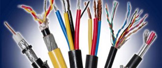
Types of cables for connection
The most common cable for home electrical wiring is a PVA connecting cable, consisting of two insulating layers.
Copper strands, stranded, twisted along the central axis. The wire is flexible, making it great for a variety of connections. The cross section is selected depending on the load:
- for a current of 6 A, PVA with a cross section of 0.75 mm is used;
- for 10 Amperes - the cross-section is 1 mm;
- for currents of 16 A – 1.5 mm.
In addition to the PVS wire, for connection there are multi-core cables ShVVP, PUGNP, PRS, KG. They are used less frequently for home wiring than PVS.
Twisting method
The simplest and most well-known method of connecting electrical wires is twisting them (twisting). Experienced electricians often call it the old-fashioned method.
Previously, this type of connection was used everywhere, but with the increase in load in the electrical network of a modern apartment, twisting became prohibited. However, this connection method must be studied first, since it is the main step in soldering and welding wires.
The main advantage of twisting is the absence of any material costs, since you only need pliers and a knife to remove the insulation. And of course, the advantage of twisting is the ease of its execution. Anyone who has held pliers in their hands can do this job without any problems.
Over time, the twist weakens, which is its main disadvantage. This process is connected with the fact that in any veins there is residual elastic deformation. Therefore, at the point of twisting, the contact resistance increases, which leads to weakening of the contact and heating of the conductor. It’s good if this defect is discovered in time and the joint can be redone, but a fire may occur.
But if for some reason you do not have the opportunity to use more reliable methods, then you definitely need to familiarize yourself with how to properly connect the wires to each other using the twisting method. To do this, you first need to strip the cores of 70-80 mm of insulation. Then, holding both conductors where the insulation ends, use pliers to grab the ends of the wires and rotate them clockwise. The main condition for reliable twisting is the simultaneous rotation of the conductors, and not alternately winding them on each other.
If the diameter of the wires is small, then twisting can be done entirely by hand. With your left hand you need to hold the conductors along the cut of the insulation, and with your right hand you need to rotate the conductors by the bend (10-15 mm) clockwise. For tighter contact at the end of the rotation, you can use pliers.
The next step is to insulate the junction of the wires. Insulating tape is used for this. To ensure reliability and protect the contact from moisture, you need to wind the tape in several layers, with 2-3 cm of overlap between the wire insulation. A very good option for insulation is the use of thermal tubes; the main thing is not to forget to put it on one of the cores.
Professional electricians advise not to stop at the stage of twisting the wires, but to strengthen the joint by soldering or welding.
Preparing a Stranded Conductor
The basis of any connection is the removal of insulation on the desired length of the conductor.
When stripping the end of a stranded copper conductor, it turns out that the thin wire cable begins to change shape. Before this, the twist was held in place by a layer of insulation, but now the hold is gone, residual elasticity causes the wires to straighten, and the rod fluffs up into individual elements. Each unconnected wire:
- Reduces the overall nominal cross-section of the joint, the permissible current density through the contact drops, the temperature rises;
- If left outside the insulation, it may cause electrical injury and short circuit.
Pre-treatment of the stripped ends of the stranded wire is required to prevent fraying and obtain a homogeneous, monolithic section.
Service
Until recently, one of the more accessible, popular methods of preparation was tinning. For this:
- The insulation is stripped to the required length, the wires are carefully twisted tightly together;
- Using a heated soldering iron, melted rosin is transferred to the surface of the core. The metal warms up, the rosin impregnates the wire rope;
- The tip of the soldering iron tip picks up solder and transfers it to the tinning site. The solder spreads over the surface of the hot wires, filling all the gaps, forming a molecular bond with the metal;
- After cooling, the remaining rosin is removed with gasoline or alcohol, and the surface is treated with sandpaper to remove possible “strings” of solder in the form of thin long needles.
Has the meaning:
- Rosin is a flux that is used during soldering to remove oxides from the metal surface, improves heat transfer and heat distribution at the soldering site. For tinning the conductors, it is prohibited to use fluxes containing acid or other active components for removing oxide, which will lead to destruction of the conductor;
- Lead-tin solder is used. The retail chain offers a huge number of solder pastes, consisting of a mixture of solder and flux. They are very comfortable. It is allowed to use only those that have a mark on the trade label indicating that the flux is not active.
The prepared tinned end is used for any type of connection - bolted, terminal, clamped, welded.
But, if the soldering iron is still hot, the easiest way is to tin the same hard conductor and connect them by soldering. The result is a strong, reliable joint with minimal contact resistance.
The method requires a soldering iron, consumables, the presence of electricity at the installation site, work skills, careful careful execution, and takes a lot of time.
Crimping
This method of preparing the stripped end of a flexible core requires the presence of press jaws and consumables - sleeves, the internal diameter of which corresponds to the diameter of the core. The process takes incomparably less time and labor than tinning:
- The stripped end of the strand is twisted tightly and placed in a sleeve;
- Press pliers compress the outer surface of the sleeve, tightly clamping the wire with the body. The resulting dents hold the cores more securely.
The finished pressed end is used in any type of joint. If you need to connect it to a single-core one, it makes sense to immediately take a sleeve, the diameter of which will allow you to place two conductors inside it. Simultaneous crimping will give a good joint. In this case, preliminary tinning of the stranded wire is not required.
Is it possible to connect cables by twisting?
According to the rules of the PUE, twisting is prohibited, as it does not provide reliable contact. It can only be used in conjunction with another connection method. It is also unacceptable to use twisting to join two different metals.
Stranded and single-core
When connecting multi-core wires, the following rules should be followed:
- strip the insulation by 4 cm;
- unwind the conductors by 2 cm;
- connect to the junction of untwisted conductors;
- twist the wires only with your fingers;
- You can tighten the twist using pliers;
- bare wires are insulated with special tape or heat shrink tubing.
Twisting solid wires is much easier. They need to be stripped of insulation, twisted by hand along the entire length, then clamped with pliers and insulated.
Twisting methods
You can do twisting in different ways. It can be made by branch, parallel or series connection. Also, to improve the reliability of contact, caps and clamps are additionally used.
Correct twisting of electrical wiring in a junction box
When twisting, you need to follow the following procedure:
- cut off power to a house or apartment;
- clear the wiring of 4 cm or more of insulation;
- unwind the wires by 2 cm;
- connect untwisted wires to the junction;
- twist the veins with your fingers;
- tighten the twist with pliers;
- insulate exposed wires.
Both single-core and multi-core cables can be connected.
Twisting of different sections
Do not twist wires with very different diameters. Such contact is not reliable and stable. You can twist wires of adjacent sections - for example, 4 sq. mm and 2.5 sq. mm. When twisting, you need to make sure that both wires wrap around each other. A thin wire should not be wound onto a thick one, otherwise the contact will be unreliable. Then you need to solder or weld the joint.
Twist caps
The caps help to reliably insulate the contact point. The cap is made of fire-resistant material, inside it there is a metal part with threads.
Making twists using caps is quite simple - you need to remove 2 cm of insulation and lightly twist the wires. A cap is put on them and turned several times until the metal wires are inside.
With terminal clamps
The contact clamp consists of a screw, a spring washer, a base, a current-carrying core and a stop that limits the spreading of the aluminum conductor. Making a connection using a contact clamp is simple - just strip the ends of the wires by 12 mm and insert them into the hole in the clamp. Contact clamps are used for both solid and stranded conductors.
After twisting, the wires need to be soldered. To do this, the wires are tinned and rosin is applied to them before twisting. The heated soldering iron is lowered into the rosin; it needs to be passed along the stripped part of the wiring. After twisting, take tin on a soldering iron and heat the joint until tin begins to flow between the turns. This method takes a lot of time, but it is reliable and of high quality.
Terminals
Terminal blocks for connecting wires provide one undeniable advantage: they can connect cores of different metals. Both here and in other articles, we have repeatedly reminded that twisting aluminum and copper wires together is prohibited. The resulting galvanic couple will result in corrosive processes and destruction of the connection
And it doesn’t matter how much current flows at the connection. Late or early, the twist will still start to heat up. The way out of this situation is precisely the terminals
Terminals are the way out of this situation.
Terminal block
The simplest and cheapest solution is polyethylene terminal blocks. They are not very expensive and are sold in every electrical goods store.
The polyethylene frame is designed for several cells, inside each there is a brass tube (sleeve). The ends of the connected wires must be inserted into this sleeve and clamped with two screws. It is very convenient that as many cells are cut from the block as it is necessary to connect pairs of wires, for example, in one junction box.
But not everything is so smooth, there are also disadvantages. At room conditions, aluminum begins to flow under screw pressure. You will have to periodically inspect the terminal blocks and tighten the contacts where the aluminum conductors are fixed. If this is not done in a timely manner, the aluminum core in the terminal block will become loose, lose reliable contact, and, as a result, spark and heat up, which can result in a fire. Such problems do not arise with copper conductors, but it would not be superfluous to periodically inspect their contacts.
Terminal blocks are not intended for connecting stranded wires. If stranded wires are clamped into such connecting terminals, then when tightening the screw under pressure, the thin wires may partially break, which will lead to overheating.
In cases where it becomes necessary to clamp stranded wires into a terminal block, it is imperative to use auxiliary pin lugs
It is very important to choose the correct diameter so that the wire does not jump out later. The stranded wire must be inserted into the lug, crimped using pliers and secured in the terminal block. As a result of all of the above, the terminal block is an ideal option for single-core copper wires
With aluminum and stranded ones you will have to comply with a number of additional measures and requirements
As a result of all of the above, the terminal block is an ideal option for single-core copper wires. With aluminum and stranded ones you will have to comply with a number of additional measures and requirements.
How to use terminal blocks is shown in this video:
Terminals on plastic blocks
Another very convenient wire connector is a terminal on plastic blocks. This option differs from terminal blocks in that it has a smooth metal clamp. The clamping surface has a recess for the wire, so there is no pressure on the wire from the screw being tightened. Therefore, such terminals are suitable for connecting any wires.
Everything about these clamps is extremely simple. The ends of the wires are stripped and placed between the contact and pressure plates.
Such terminals are additionally equipped with a transparent plastic cover, which can be removed if necessary.
Self-clamping terminals
Wiring installation using such terminals is simple and quick.
The wire must be inserted into the hole to the very end. There it is automatically fixed using a pressure plate, which presses the wire to the tinned busbar. Thanks to the material from which the pressure plate is made, the clamping force does not weaken and is maintained all the time.
The internal tinned busbar is made in the form of a copper plate. Both copper and aluminum wires can be fixed in self-clamping terminals. These terminals are disposable.
And if you want clamps for connecting reusable wires, then use terminal blocks with levers. They lifted the lever and inserted the wire into the hole, then fixed it there by pressing it back. If necessary, the lever rises again and the wire protrudes.
Try to choose clamps from a manufacturer that has proven itself well. WAGO clamps have especially positive characteristics and reviews.
The advantages and disadvantages are described in this video:
Choosing a method for connecting conductors
There are many ways to connect conductors. You need to choose a possible option taking into account the situation. So, if a temporary connection is necessary, you can simply twist or clamp the conductors between the bolt and nut. It is better to fix shaped or winding wires of large cross-section by welding or soldering.
Watch this video on YouTube
Cable connection sleeves or couplings are ideal for splicing cables. Connecting insulating clamps are well suited for fixing small cross-section wires and if you have the right size clamp. Terminal blocks are needed to assemble the circuit. Piercing and branching terminals are used to connect additional loads to an existing network.
Connection of stranded and solid conductors
This connection begins with selecting the cross-section of a stranded wire to a single-core one. A stranded conductor should not be smaller than the cross-section of a single conductor, otherwise it will burn out at the junction. They are fixed by soldering or welding, or by crimping when using cable sleeves.
When soldering, the wires are cleared of insulation, then the stranded wire is wound onto a single-core wire, and then soldering is performed. The soldering area is then protected with insulation. When crimping, the contact points are cleaned, a sleeve is put on, which is crimped with crimping pliers in several places.
Connecting wires with cross-sections of different diameters
Connecting wires with sections of different diameters is possible by calculating the current density in sections; if the density in sections is acceptable, then they can be connected by soldering, twisting, terminals or bolted connections. Connection technologies do not differ from the process of connecting wires with the same cross-section and were discussed above.
Connecting larger wires
This connection method is quite complicated with a large contact area. If the cross-section of rectangular wires is too large, fixation is only possible by welding and often cannot be done at home due to the need to heat the conductors to a high temperature. After welding the conductors, it is necessary to test the resulting contact.
When connecting stranded wires or large cross-section cables, you can use the cable connector already mentioned above.
Connecting broken wires in the wall
Often in everyday life situations arise when a breakdown of electrical wiring occurs in the wall. This often happens during renovation work. Initially, the electrical wiring must be de-energized and the plaster must be dismantled at the site of the repair work.
Afterwards, the insulation is stripped from each end of the damaged wire, and the ends are coated with molten lead-tin solder using a regular soldering iron. Immediately think through the insulation for the soldering area. It is good to use heat shrink tubing based on the size of the area being repaired. The tube is placed on one end of the conductors.
Next, a wire with a cross-section no smaller than the broken wire is selected, it is cut off and soldered first to one end of the wire, then to the other. At the same time, the length of the extended conductor should ensure the strength of the contacts. It shouldn't be too small or long. Finally, a tube is placed over the area, which, when heated with a hairdryer, tightly clasps the welded area.
Copper and aluminum connection
How to connect copper and aluminum wire is discussed in more detail in our article. Connecting opposite wires is possible using the bolted connection discussed earlier. However, most often fixation is carried out using copper-aluminum sleeves (CAS) for crimping. On the one hand, the sleeve is made of aluminum, on the second, copper. The aluminum side of the sleeve is larger because aluminum has a lower current density than copper. The sleeve is placed on the ends of the wires with the same metal and crimped with a press.
Twist connection
If for some reason you do not have the opportunity to use other methods of connecting electrical wires, you can use twisting, just do it well. Very often it is used as a temporary option and is subsequently replaced by more reliable switching methods.
How to connect wires using twist? To begin with, the cores are stripped to 70-80 mm. The main thing is to twist all switched conductors into one single twist at the same time, and not wind one around the other.
Many people mistakenly begin to twist the wires together from the place where the insulating layer ends. But it is better in this place to clamp both wires with one pair of pliers, and with the other, grab the ends of the wires and perform rotational movements in a clockwise direction.
If the wire cross-section is small, you can twist it by hand. Align the conductors along the cut of the insulation and hold them firmly in this place with your left hand. Bend all switchable ends into one single bend at an angle of 90 degrees (a bend length of 10-15 mm will be enough). Hold this bend with your right hand and rotate clockwise. This must be done firmly and firmly. If it is already difficult to twist your hands at the end, use pliers as described above. As soon as the twist becomes smooth and beautiful, you can trim the bend.
You can connect several wires this way, but then to make it easier to twist them, make the bend longer, somewhere around 20-30 mm.
How to properly twist wires is shown in this video:
There is also a way to twist wires using a screwdriver, see about it here:
For information on twisting wires using a special tool, see here:
Now the resulting twist must be carefully insulated. Electrical tape is used for this. Do not spare it, wind it in several layers, and insulate not only the connection itself, but also step 2-3 cm over the core insulation. This way, you will ensure the insulating reliability of the twist and protect the contact connection from moisture.
You can also insulate the connection of wires using heat pipes. The main thing is not to forget to put the tube on one of the cores to be connected in advance, and then push it into the place where it is twisted. When exposed to heat, the thermal tube shrinks, so slightly heat its edges and it will firmly grip the wire, thereby providing reliable insulation.
If the twisting is done well, there is a chance that it will serve you for many years, provided that the load current in the network is normal. But it’s still better not to stop at this stage and strengthen the joint by welding or soldering.
Crimping method
Almost the entire space of the sleeve should be filled with conductive ends, but at the same time there should be some free space left. For this reason, it is necessary to select the correct dimensions of the sleeve, since the quality of the crimp depends on this factor.
Actually, this is the main difficulty of this method of connecting wires - the sleeve should not be too large or small. The procedure itself looks like this:
- First, you should strip the ends of the wires from insulation (the length of the section should slightly exceed the dimensions of the sleeve).
- Each core should be stripped to bare metal. Oxides can be removed with fine-grain sandpaper.
- Next, the wires are twisted in a way that is already familiar to us.
- Upon completion of the process, the sleeve is compressed with special pliers.
Connecting a stranded wire to a single-core wire does not cause any difficulties. Difficulties arise only at the stage of selecting cartridges and the presence of pliers. Of course, you can use pliers or pliers for this purpose. However, no one can give any guarantees regarding the reliability of such a connection.
Expert opinion
Viktor Pavlovich Strebizh, lighting and electrical expert
Any questions ask me, I will help!
To do this, the insulation is removed from it in the right place, after which an additional conductor is connected using simple twisting. If there is something you don’t understand, write to me!
Which is the best way to connect wires?
As a rule, the wires are connected to each other in the following ways:
- By welding. It is considered the most reliable method, but difficult to implement, since it requires a welding machine, as well as skills in handling it.
- Using terminal clamps. Affordable and reliable connection.
- Using soldering. The connection is reliable if the soldering points do not overheat.
- Using crimping with sleeves. Although the connection is quite reliable, a special tool is required.
- Using special spring clamps. Under certain conditions, it provides good contact, especially since the installation of such clamps does not require a long time.
- With bolts. This type of connection is used in difficult situations when, for example, it is necessary to connect a copper conductor to an aluminum conductor.
Which method is appropriate for a particular case is determined by the availability of certain information. It is necessary to familiarize yourself with the wiring design, with their cross-section, with possible loads, with the type of insulation, with the nature of the conductors (single-core or stranded), etc. You will also have to take into account the operating conditions.
How to connect headphone wires
Sometimes the cable near the plug breaks off in working headphones, but there is a plug from faulty headphones. There are also other situations in which it is necessary to connect the wires in the headphones.
- cut off a broken plug or an unevenly torn cable;
- strip the external insulation by 15–20 mm;
- determine which of the internal wires is common and check the integrity of all conductors;
- cut the internal wiring according to the principle: leave one alone, common by 5 mm and the second by 10 mm. This is done to reduce the thickness of the connection. There can be two common conductors - each earphone has its own. In this case they are twisted together. Sometimes a screen is used as a common conductor;
- strip the ends of the wires. If varnish is used as insulation, it will burn off during the tinning process;
- tin the ends to a length of 5 mm;
- put a piece of heat-shrink tubing on the wire 30 mm longer than the expected length of the connection;
- put pieces of thinner heat-shrinkable tube 10 mm long on the long ends, do not put on the middle (general) ends;
- twist the wires (long with short, and middle with middle);
- solder the twists;
- bend the soldered twists outward to the unprotected edges, slide pieces of thin heat-shrinkable tubing onto them and heat it with a hairdryer or lighter;
- Slide a larger diameter heat-shrinkable tube onto the joint and warm it up.
If everything was done carefully and the color of the tube was matched to the color of the cable, then the connection will be invisible and the headphones will work no worse than new ones.
Expert opinion
Viktor Pavlovich Strebizh, lighting and electrical expert
Any questions ask me, I will help!
After the soldering has cooled, it is insulated with electrical tape or a piece of heat-shrinkable tubing is put on it and heated with a hairdryer, lighter or soldering iron. If there is something you don’t understand, write to me!