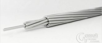
To connect objects to the centralized power supply line, wires with an integrated load-bearing element are used that can withstand wind loads. Before connecting the SIP with a copper cable at the entrance to the house, it is necessary to study the regulatory documentation and purchase the necessary components. Switching errors lead to problems with the power supply to the facility.
Features of connecting different wires
Direct connection of copper and aluminum cores is not allowed, since the metals form a galvanic couple. The contact of dissimilar materials has increased resistance, leading to heating of the cables when power is supplied and the load is connected.
Since SIPs are not allowed to be introduced into buildings, internal wiring is carried out on the basis of VVG-NG wire, which does not support combustion. The developer or home owner must correctly connect the aluminum and copper conductors, otherwise the wiring or electrical panel may catch fire.
About connecting cables
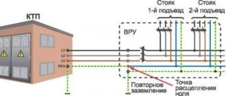
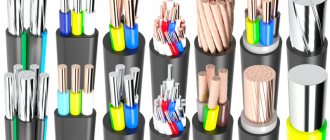
SIP cable is used to build power lines and organize branches to residential or industrial buildings. The wire is inserted into a distribution board with a central machine and a meter. The box is placed outside the house (for example, on a concrete or wooden power line support) or inside the building. Depending on the installation location, different methods are used to connect SIPs to copper wiring.
On line support
For SIP branches, piercing clamps are used to ensure the tightness of the contact. To connect a copper cable, you need bimetallic sleeves with subsequent protection of the contact from moisture.
For residential buildings, VVG-NG wire with 3 monolithic cores with a cross-section of at least 10 mm² is most often used (depending on the estimated load power). You should not insert cables of the SIP series into the shield and connect the aluminum conductors directly to the central machine, since it will not be possible to ensure tight contact between the core and the terminals.
On the wall of the house
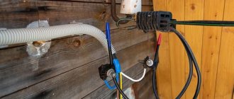
If the junction box is located on the external wall of the house and is protected from moisture penetration, then bimetallic sleeves can be used. If the shield is mounted indoors, then the SIP is mounted on the wall with an anchor, and then a piece of copper cable with non-flammable insulation is connected (for example, VVG-NG). The wiring is run through a plastic or metal pipe into the house and then connected to the central switch.
The sleeves are insulated with a shrink tube or rubber-based protective tape, which vulcanizes in air and forms a durable layer.
Connecting SIPs to each other
This type of SIP connection is used when it is necessary to connect two parts of the cable to each other or to make a branch from the main power supply line to other buildings on the site, as well as to create a branch from the power line on a support pole. To connect two parts of the SIP cable, special MJPT connecting sleeves are used, and piercing clamps are used to create branches. Let's consider both types of SIP connections separately from each other.
- MJPT connection sleeves. This type of sleeve is used for butt jointing of cores of self-supporting insulated wires. The technology for installing such elements is quite simple, but requires the use of a special hand press with a hexagonal matrix. To connect SIP conductors, current-carrying and self-supporting, it is necessary to insert the ends of the wires into this sleeve from different sides and perform multiple crimping of the structure. The result is a strong, sealed connection that can withstand heavy mechanical loads. The MJPT sleeve is a sectional aluminum tube enclosed in a sealed polymer housing with end waterproofing rings. This design allows you to reliably protect the connection from penetration of atmospheric moisture and dust.
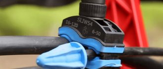
- Piercing clamps. To connect the cores and create branches from the main line on the supporting pole, the same piercing clamps are used as for connecting copper and aluminum conductors, since they do not create a galvanic pair between dissimilar metals and the contact is not destroyed. Installation of piercing clamps on the main line is quite simple and can be done without turning off the power supply, but in compliance with all safety regulations. At the first stage, the main cores are separated by special plastic separating wedges and clamps are installed and tightened on them. Next, the ends of the branches are also clamped in the corresponding clamp socket and protective caps are put on them. The branch line must be secured to the pole with anchor retaining devices.
Attention! When installing piercing clamps, their re-installation is not allowed, since the clamping head of the product is disposable. You cannot install more than one core in one clamp socket.
Safety precautions
The SIP cable is manufactured in accordance with GOST 31946-2012, which prescribes the use of wire for organizing outdoor overhead power supply lines. The insulation is made of polyethylene, which is resistant to ultraviolet light and low temperatures, but supports combustion. There is a version of SIP with additional marking with the letter “n”, designed for installation along the wall of the house. The insulator is made of self-extinguishing polymer and does not support combustion. But regardless of the type, the SIP cable cannot be used inside the house.
Options for connecting dissimilar wires
To connect cables with cores made of dissimilar metals, clamps or couplings are used to prevent direct contact of the materials. Otherwise, an electrochemical couple appears on the connection line. Metals are covered with a layer of oxides that have high resistance, or are destroyed. Since the SIP cores are made of aluminum, and the wiring inside the building is made of copper, reliable separation of materials at the junction lines is necessary.
Piercing type clamps
The clamps are suitable for connecting cores made of dissimilar metals and do not create electrochemical vapors that destroy materials.
For installation, simply insert the wires into the holes and then tighten the bolts. The pointed tips of the clamps pierce the insulation and go deeper into the metal of the core. The clamp body is made of polymer material with the addition of fiberglass to increase strength. The casing protects the contact from moisture and withstands exposure to ultraviolet radiation and precipitation.
Bolted
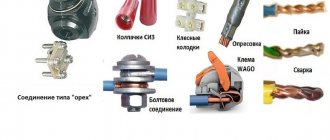
Bolting technology is used for temporary joining of cables with copper and aluminum conductors, but is not used for SIP. The method is based on installing cores twisted into a ring on the threaded part. To improve the quality of contact, steel washers are placed between the head, nut and mating cores. After tightening, the bolt is protected with a shrink tube or a layer of insulating tape. The resulting connection is not designed for mechanical loads and does not comply with the rules of the PUE.
With terminals
When laying cables inside the house use:
- WAGO terminals with reusable lever clamps. Before switching, the insulator layer is removed from the cores to a length of 8-10 mm. The products provide reliable contact and are not destroyed when connecting a powerful load. The casing does not protect the conductors from exposure to precipitation.
- Walnut-type clamps with a polymer body and metal plates, tightened with screws. WAGO or “nut” clamps can only be used for wiring inside the house; branches from SIPs using terminals are not allowed.
Connection of SIP with VVG cable
When introducing an electrical line into a structure, VVG cable or another similar brand of copper conductor is most often used. Direct contact of copper and aluminum conductors during installation is extremely undesirable. In this case, increased resistance to electric current occurs at the junction, which leads to overheating of the conductors, accelerated corrosion and destruction. Breaking the contact can lead to various negative consequences, including a fire. To prevent this from happening, special methods should be used to separate copper and aluminum conductors from each other.
The simplest of them is to connect a copper and aluminum core using a threaded connection. For this option you will need a steel bolt with a nut of suitable diameter, several simple washers and one engraving washer. Installation of such a connection is very simple: a washer is installed between dissimilar conductors to prevent direct contact of copper with aluminum. It is advisable to choose washers coated with pure tin or solder based on it. After tightening the bolt, the connection must be wrapped with insulating tape. This method is very simple, but extremely unreliable, so it is practically not used.
For a better and more reliable connection of SIP with copper cable, completely different methods are used, which are performed using specially designed connecting elements, such as piercing clamps, monolithic aluminum-copper sleeves and branching clamps. Let's consider each option separately.
- Piercing clamps. With this method, the insulation from the cores of the connected cables is not removed. A copper and aluminum conductor with an insulating layer is inserted into the corresponding hole in the clamp, after which the entire structure is tightened with a threaded connection. Tightening can be done either with one top bolt or with separate bots for each core of the connected cables. The body of the piercing clamp is made of durable polymer material with glass fiber reinforcement. It provides reliable protection to the connection from the effects of negative environmental factors.
- Branching compressions. Among experts they are called “nuts”. These connecting elements have in their design three bimetallic plates and tightening bolts, which are enclosed in a protective housing. To connect SIP to copper cable, you need to remove the insulation from the cores, insert it between the plates and secure with bolts. The use of clamps is more preferable for aluminum cores of self-supporting wires, since they are very sensitive to the notches that arise from the spikes of piercing clamps.
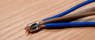
- Bimetallic sleeves. These connecting elements are made of copper and aluminum parts combined into one monolithic structure. The connection of dissimilar cores is carried out by crimping. The conductors are stripped and inserted into a sleeve, which is crimped with a special tool, thereby creating reliable contact. The connection point is sealed with a special heat-shrinkable tube filled with an insulating gel. Under the influence of high temperature, the tube contracts and reliably protects the contact from the negative influence of the external environment.
An alternative to all of the above methods of connecting self-supporting insulated wires with VVG copper cable or other brands is the direct insertion of self-supporting insulated wires into the building with a connection to the electrical panel. The rules of the PUE and the requirements of energy supply organizations do not prohibit this option, as it reduces the possibility of electricity theft.
Important! For wooden and other structures that can burn, the installation of self-supporting insulation insulation is prohibited by the rules of the Electrical Installation Rules. In this case, it is necessary to make a transition from a self-supporting cable to a copper cable such as VVG or any other suitable design.
Installation sequence
To connect using GAM bimetallic sleeves you must:
- Remove the insulation from the SIP cable core and put on the coupling.
- Deform the retainer using a 6-sided mandrel, moving the tool along the sleeve and performing successive compressions.
- Strip the copper cable of insulation, insert it into the coupling and secure the cores with a hexagonal mandrel. The length of the exposed area depends on the dimensions of the sleeve.
- Place a shrink tube on the metal elements; to increase the tightness, you can use several protective covers.
If you plan to use clamps, then you need to bring the cable to the wall of the house and secure it with an anchor. Then a clamp is put on the wires (main and branches) and the bolt is tightened. It is necessary to follow the installation rules: with a weak force on the key, the contact pins do not penetrate well into the cable cores. Protective caps are placed on the exposed ends.
The main line entering the house is laid through a pipe that prevents melt or rain moisture from flowing into the shield.
How to connect SIP wires to each other
Methods for connecting SIP wires largely depend on the brand. Therefore, if you need to connect SIPs to each other, then first of all, you need to find out the brand of wire.
For example, SIP 4 is not allowed to be connected to each other in spans. Such a SIP wire can only be connected using a support so that no load is placed on the wire cores.
Therefore, it is possible to connect the SIP-4 wire using only anchor clamps.
Other brands of SIP, for example, SIP-1 and SIP-2, can be connected with special clamps, such as: GSI-F and MJPT. These types of wires can be connected even in spans, using special clamps for these purposes.
Connecting SIP wires with sleeves
From the technical side, connecting SIP wires with sleeves shows itself best.
At the same time, when crimping SIP wires with sleeves, it is important to follow the following rules:
- The connected conductors of the SIP wires (phase and neutral) should not be opposite each other. To do this, the SIP wire must be cut in the form of a “ladder” so that the conductors are spaced apart and the sleeves do not come into contact with each other;
- After this, you need to remove the insulation from the SIP core, strictly to the required depth of the sleeve. At the same time, no open core should be visible from the sleeve for crimping the SIP wire;
- Then the core is inserted into the sleeve and rests its edge against the partition in the center;
- Using a hydraulic press, the liner is pressed directly through the insulation;
- If, after crimping the sleeve, contact lubricant leaks out, it must be removed with a piece of cloth.
You should know that for crimping SIP wires of different diameters, there are special sleeves (with a transition).
Errors when working with sleeves
The main problems when using sleeves are:
- the use of couplings with an internal hole that does not correspond to the diameter of the metal core;
- the use of connectors cut into several parts (for example, for the purpose of economy or in the absence of the necessary stock of components on site).
The use of sleeves with a small cross-section
Installation of a sleeve with an insufficient cross-section requires a reduction in the diameter of the wire. As a result, the power supply line cannot withstand the rated load, the contact overheats and is destroyed. Removing part of the metal from the core negatively affects the mechanical strength of the cable. Under the influence of wind loads, the core breaks, and special equipment is needed to locate the damage.
The sleeves are too wide
Installing a tip with an increased diameter will not allow you to tightly enclose the metal core of the cable. Winding the wire or bending the end of the strand can partially eliminate the problem, but in this way it will not be possible to increase the mechanical strength of the contact. When connecting powerful equipment to the power line, sparks appear in a poorly crimped joint, carbon deposits cause an increase in resistance and heating of the coupling until the insulation ignites.
Cutting shells
To reduce costs, novice installers cut metal sleeves into several parts. Manufacturers prohibit shortening connectors, since the short length of the clamp will not allow the wiring to be firmly connected. It is inconvenient to squeeze sections of sleeves with pliers; poor compression contributes to the appearance of sparking in the contact when a powerful load is connected. Subsequently, the house owner will have to reconnect the wires, so such “savings” will lead to additional costs.
