Device and principle of operation
A megohmmeter is a device for checking insulation resistance. There are two types of devices - electronic and pointer. Regardless of the type, any megohmmeter consists of:
- Constant voltage source.
- Current meter.
- Digital screen or measurement scale.
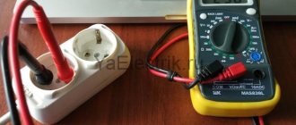
- Probes, through which voltage from the device is transmitted to the object being measured.
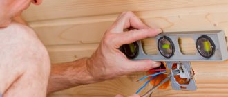
This is what a pointer megaohmmeter looks like (on the left) and an electronic one (on the right)
In pointer instruments, the voltage is generated by a dynamo built into the housing. It is driven by a meter - it rotates the handle of the device with a certain frequency (2 revolutions per second). Electronic models take power from the mains, but can also run on batteries.
The operation of the megohmmeter is based on Ohm's law: I=U/R. The device measures the current that flows between two connected objects (two cable cores, core-ground, etc.). Measurements are made with a calibrated voltage, the value of which is known; knowing the current and voltage, you can find the resistance: R=U/I, which is what the device does.
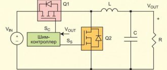
Approximate diagram of a magaohmmeter
Before testing, the probes are installed in the appropriate sockets on the device, and then connected to the object being measured. During testing, a high voltage is generated in the device, which is transmitted to the object being tested using probes. Measurement results are displayed in mega ohms (MΩ) on a scale or screen.
Cable insulation resistance measurement
It is often necessary to measure the insulation resistance of a cable or wire. If you know how to use a megohmmeter, when checking a single-core cable it will take no more than a minute; with multi-core cables you will have to tinker longer. The exact time depends on the number of wires - you will have to check each one.
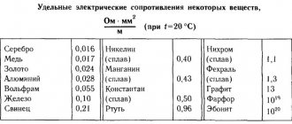
Select the test voltage depending on the network voltage with which the wire will operate. If you plan to use it for 250 or 380 V wiring, you can set it to 1000 V (see table).
Checking a three-core cable - you don’t have to twist it, but try on all pairs
To check the insulation resistance of a single-core cable, we attach one probe to the core, the second to the armor, and apply voltage. If there is no armor, attach the second probe to the “ground” terminal and also apply test voltage. Let's look at the readings. If the arrow shows more than 0.5 MOhm, everything is normal and the wire can be used. If it is less, the insulation is broken and it cannot be used.
You can check the multi-core cable. Testing is carried out for each core separately. In this case, all other conductors are twisted into one bundle. If at the same time it is necessary to check the ground fault, a wire connected to the corresponding bus is added to the common harness.
If the cable has a screen, metal sheath or armor, these are also added to the bundle. When forming a tourniquet, it is important to ensure good contact.
The insulation resistance of socket groups is measured in approximately the same way. All devices are turned off from the sockets and the power to the panel is turned off. One probe is installed on the ground terminal, the second - in one of the phases. Test voltage - 1000 V (according to the table). Turn it on and check it. If the measured resistance is greater than 0.5 MΩ, the wiring is normal. We repeat with the second core.
If the wiring is old - there is only phase and zero, testing is carried out between two conductors. The parameters are similar.
Safety rules when working with a megohmmeter
When testing electrical equipment, electrical personnel with an electrical safety group of at least third must be allowed to work with a megohmmeter. Even if measurements are made at home, those who intend to use a megohmmeter should familiarize themselves with the basic safety requirements:
- When testing, dielectric gloves should be used; unfortunately, this requirement is often ignored, which leads to frequent injuries.
- Before testing, it is necessary to remove unauthorized persons from the tested object, and also post appropriate warning posters.
- When connecting probes, you must touch their isolated areas (handles).
- After each measurement, remember to connect a portable ground before disconnecting the control cables.
- Measurements should be carried out only with dry insulation; if its humidity exceeds permissible limits, the tests are postponed.
vote
Article rating
Taking measurements
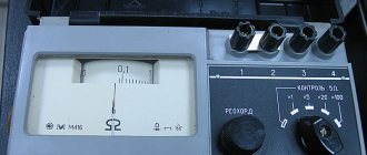
And yet, in the question of how to measure grounding resistance, it is better to use a megohmmeter rather than a multimeter. The best option is considered to be a portable electrical measuring device M-416. Its operation is based on the compensation measurement method; for this purpose, a potential electrode and an auxiliary ground electrode are used. Its measuring limits are from 0.1 to 1000 Ohms, the device can be operated at temperatures from -25 to +60 degrees, power is provided by three 1.5 V batteries.
And now step-by-step instructions for the entire process on how to measure the resistance of the ground loop:
- Place the device on a horizontal, flat surface.
- Now calibrate it. Select the “control” mode, press the red button and, while holding it, set the arrow to the “zero” position.
- There is also some resistance in the connecting wires between the terminals; to minimize this influence, place the device closer to the ground electrode being measured.
- Select the desired connection diagram. You can check the resistance roughly; to do this, connect the terminals with jumpers and connect the device using a three-terminal circuit. For accurate measurements, the error caused by the connecting wires should be eliminated, that is, the jumper is removed between the terminals and a four-clamp connection diagram is used (by the way, it is drawn on the cover of the device).
- Drive the auxiliary electrode and probe rod into the ground to a depth of at least 0.5 m, keep in mind that the soil must be dense and not bulky. To hammer in, use a sledgehammer, the blows should be straight, without swinging.
- Clean the place where you will connect the conductors to the ground electrode with a file to remove paint. Use copper conductors with a cross section of 1.5 mm2 as conductors. If you use a three-clamp circuit, then the file will act as a connecting probe between the ground electrode and the terminal, since a copper wire with a cross-section of 2.5 mm2 is connected on its other side.
- And now we move on directly to how to measure grounding resistance. Select the range “x1” (that is, multiply by “1”). Press the red button and turn the knob to set the arrow to zero. For larger resistances, it will be necessary to select a larger range (“x5” or “x20”). Since we chose the “x1” range, the number on the scale will correspond to the measured resistance.
It is clear how grounding is measured in the following video:
Basic Concepts
The resistance of the grounding device (it is also called resistance to current spreading) has a directly proportional relationship with the voltage and inversely proportional to the current spreading to the ground.
There are three types of grounding:
- working. With its help, certain places are grounded and used during the operation of electrical equipment;
- lightning protection. Lightning rods are grounded in order to redirect currents that arise under the influence of lightning to metal structures;
- protective. Used to protect against the damaging effects of electric current if someone inadvertently comes into contact with a part that should not carry current during normal operation.
There are several methods for measuring the resistance of grounding devices, which will be discussed in more detail. Measurement methods are determined by specialists from the electrical engineering laboratory and depend on the specific operating conditions of the equipment.
How to measure ground loop resistance - a review of techniques
08/15/2016 no
Grounding resistance must be measured to make sure that it matches the requirements of the PUE (electrical installation rules) Ch. 1.8. as well as PTEEP pr. 3.3.1. Measurements taken in an electrical installation with a solidly grounded neutral (the voltage of which is below 1000V) must comply with the following standards. It doesn’t matter whether in winter or summer, the value should not exceed 8, 4 and 2 Ohms at voltages of 220, 380, 660 V (for sources with three-phase current), respectively, or 127, 220 and 380 V for sources with single-phase current. For electrical installations where an insulated neutral is used (voltage below 1000V), the resistance of the grounding loop must correspond to clause 1.7.104 of the PUE and is calculated using the formula Rз * Iз < 50 V. Below we will consider the main methods for measuring the loop, as well as instruments that can be used for this .