This skill is not useful every day, but it is better to find out in advance how to check the voltage in an outlet with a multimeter and what it should show. In addition to voltage, the electronic tester is capable of measuring current strength and resistance of wires, for which the connection of the plugs on the device must be swapped. Their correct connection must be carefully monitored - if measurements are taken incorrectly, a short circuit will occur.
A little theory - how measuring instruments are connected
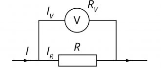
An electronic multimeter combines several different devices that are connected to a section of the circuit in different ways.
To use it correctly, you need to know how voltage is measured, and how current is measured, and connect the device correctly. When the wires are simply connected to a working power source, an electrical voltage appears on them, which can be measured between plus and minus (phase and zero). This means that the voltage can be measured both with a load (operating device) connected to the network and without it.
Electric current appears in the wires only when the circuit is closed - only then does it begin to flow from one pole to the other. In this case, current measurements are carried out when the measuring device is connected in series. This means that the current must pass through the device and only in this case will it be able to measure its value.
Of course, in order for the measuring device not to influence the current it measures, the resistance of the multimeter should be as low as possible. Accordingly, if the device is configured to measure current, and you mistakenly try to measure voltage with it, a short circuit will occur. True, not everything is clear here either - current and voltage measurements with modern electronic multimeters are carried out with the same connection of the terminals to the device.
If you recall at least superficial school knowledge about electrical circuits, then you can formulate the rules for measuring voltage and current as follows: the voltage is the same on parallel-connected sections of the circuit, and the current is the same when the conductors are connected in series.
To avoid errors, before taking measurements, be sure to check the markings located near the contacts of the multimeter and its mode switch.
What current flows in a 220V home outlet and how do modern electrical consumers spoil it?
There are two main types of voltage used inside our homes, shown in the graph below:
- permanent. The sources of electricity are: chemical current sources (accumulators, batteries), as well as rectifiers, power supplies, current drivers;
- alternating sinusoidal, generated by generators of energy systems and coming through power supply lines through transformer substations.
These types of voltages form direct or alternating current in the network when a load is connected.
In other words, the current waveform in the outlet follows the appearance of the voltage, and its value depends on the applied resistance. I’ll explain with a picture demonstrating Ohm’s law I=U/R. This is a fundamental rule that works flawlessly when transmitting electricity.
The water in the washstand bottle is raised to a height (potential difference) and has potential energy. This is analogous to the voltage applied to the contacts of a socket.
When the plug is closed, the water does not flow: its flow is not able to overcome the enormous resistance. To wash your hands, you need to turn the tap and create a stream, the thickness of which can be adjusted with the valve.
In a similar way, current arises in the socket. It will begin to flow (the movement of charged particles occurs) only when a consumer with a certain resistance is connected to its contacts, which regulates the force.
Of all three parameters (U, I, R), we are most interested in the hard-working current I. After all, only it does useful work: it turns the electric motors, heats the heating element, illuminates the room...
It is important for us to remember that the current increases:
- increase in voltage;
- or a decrease in resistance.
With the opposite action, it decreases. Even its unit of measurement, 1 ampere, is defined as 1 volt divided by 1 ohm.
All this is explained in the school physics curriculum for all students. Moreover, Ohm's law should be applied to any type of electricity, regardless of the type of current flowing: direct or alternating.
It is simply conventionally accepted that single-phase alternating current is directed to the consumer from the generator phase potential, and returns along the working zero conductor, moving along a closed circuit.
An important indicator of its sinusoid is the frequency, measured in Hertz (abbreviation Hz). The frequency of the entire European network and Russia has a standard value of 50Hz. Overseas, in the country of the United States, a different indicator is set. All electrical equipment there operates at a frequency of 60 hertz (60 cycles per second).
Direct current has a polarity direction from the plus of the voltage source to its minus. It is most often produced by batteries, accumulators, galvanic cells of automobile and air transport, and solar stations of home devices.
It powers mainly portable lighting devices, mobile gadgets, for example, smartphones, detectors (metal detectors), radio receivers, measuring instruments: the same multimeters...
4 most important sinusoidal voltage parameters
It's time to remember the trigonometric sine function, which describes the current values at a certain point in time with a repeating graph. For us this will be the expression: u=sin(ωt).
We will consider fluctuations within one period (highlighted in brown).
The horizontal angle showed the angle in radians, the vertical - sine, varying from -1 to +1. If we substitute unity for the maximum value (amplitude Um or Im), we obtain a formula for expressing voltage or current at any point in the period.
u=Um·sin(ωt), i=Im·sin(ωt).
Classical electrical engineering primarily takes into account four characteristics:
- signal amplitude;
- the frequency f of its oscillations per unit time or period T, which are related by the formula f = 1/T;
- a shape described by a sinusoidal expression;
- phase shift angle φ relative to the origin.
Based on them, I will try to evaluate the electrical signal coming to us from power engineers.
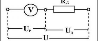
What a Voltmeter Shows: 3 Methods for Measuring a Sine Wave Signal
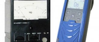
It's time for the experiment. I took an extension cord and inserted a voltmeter into each outlet. One is an old Soviet tseshka (Ts4324 tester), and the second is a Chinese digital multimeter Mestek MT-102.
Their accuracy classes (an instrument indicator important for a metrologist) according to the factory documentation for this particular measurement are:
- the tester has 4.0;
- multimeter – 1.0.
The measured reading of a digital voltmeter is 236 volts, and on an analog device it is 240. A fundamental question arises: where on the sine wave graph is their reference point and what does each voltmeter actually show (although I am happy with both in everyday life: they are of the same order).
To start measuring, it makes sense to use amplitude as the maximum value of the signal. You will have to build on it further in order to form an average reading of high-speed processes common to all cases.
Mathematically, they are described by three methods and calculated using the formulas as:
- average;
- medium-straightened;
- or root mean square expression.
The average value is calculated through an integral and is rarely used in practice. Graphically, it can be represented by the displacement of the harmonic relative to the abscissa axis.
Formula:
The average rectified voltage is somewhat more complicated to calculate, but graphically it can be represented as the process of rectifying the lower half-wave with further integration of the signal.
In practice, it is calculated as a multiplication of a coefficient of 0.64 by the amplitude.
Formula:
The effective voltage is taken as the square root of the sum of squares over one period.
Formula:
In practice, it is calculated as the amplitude divided by the square root of two.
An important practical conclusion: the effective value of the signal is less than the amplitude of the sinusoid by the root of two, which is the basis for using the coefficient 0.707 = 1/√2.
according to the formula Ud = Um/√2 . But they do it in different ways:
- an accurate method of determination, which forms the basis of laboratory meters;
- simplified.
It is interesting to understand that analog instruments do not have the ability to calculate the parameters of a sinusoid. They immediately measure the actual value without any converters. That’s why they still work for energy specialists.
How 2 types of digital electrical meters work
In practice, they exist with two operating principles:
- True RMS;
- RMS.
The difference in the readings of electrical appliances and the accuracy of these groups is clearly visible in the control photo, where, on a special installation, an electronic generator produces an almost sine wave, and its value is simultaneously measured by voltmeters of both groups. Everything is clear, but how to make a choice?
The devices operate in the same accuracy class, defined for a pure sine wave, and the voltage indicator varies from 229 to 240 volts. And this is not the limit of the difference.
True RMS multimeters (the markings are indicated on the front and in the passport) are the most complex, expensive, and measure the rms or rms voltage value immediately. Their testimony is closest to the truth.
RMS brand devices are simpler, cheaper, measure the average rectified value and simply convert it into effective value by multiplying by the average difference coefficient for a sine wave of 1.1. This simplified calculation algorithm was laid down by their manufacturer.
When the shape of the sine is even slightly distorted, then errors are immediately applied to the voltmeter reading.
The word “True” is translated from English as true. It refers to devices that operate on the principle of measuring the root mean square value, which takes into account the distortion of the sinusoidal signal.
If there is interference in the network, RMS group devices can measure with an error in readings of up to two times.
But it's not all bad with RMS class measuring devices. Their use is fully justified when evaluating direct current or pure alternating sine without interference. The problem is that you need to know this in advance, before the measurement begins. And these are most often laboratory conditions.
In a modern home, the use of True RMS measurement devices is more justified. They accurately calculate the effective value of not only a sinusoidal, but also another type of alternating signal (triangular sawtooth, square, meander, etc.). Decide for yourself what you choose: the difference is explained.
Now I will try to briefly explain everything about the interference of alternating voltage and current superimposed on an ideal sine wave and why we need to take their presence into account in everyday activities.
What signal distortions occur in modern household wiring?
First, let's look at the work done by an alternating current of a sinusoidal shape and its expression by the effective value. According to Ohm's law, it is formed by ideal voltage.
Let's imagine a graph of a sinusoid and the effective value of the current for it iд, which flows through a purely active resistance, for example, a heating element, a resistor.
The work done by the current iд will be equal to the work done by the direct current iп of the same strength. I specially highlighted this area on the graph with a colored rectangle.
For myself, I long ago made a simple rule: an active value is a value of an alternating signal that does the same work as its constant analogue.
In principle, this is an ideal theoretical case. But all our activities are far from it. Therefore, we need to know all the nuances in order to make adjustments and take into account various complex issues that occur in the modern electricity network.
What current is created by modern household appliances
Electrical current loads of an alternating network are divided into two classes:
- linear;
- not linear.
Linear are those that are described by a straight line graph on the coordinates of the current-voltage characteristic (CVC), when the voltage increment changes the current strength strictly proportionally.
In this case, the resistance does not make any adjustments to the deviation of the current-voltage characteristic from a linear character. It is called active or resistive. This includes powerful electric stoves, kettles and boilers with heating elements, incandescent lamps for lighting devices.
All other resistances have a different effect on the nature of current flow through them.
Reactive loads are considered to be inductances (chokes, windings of transformers, electric motors) and capacitances (capacitors). The phase of the vector shifts on them.
The current passing through the capacitor leads the voltage sine wave by 90 degrees or a quarter of a period.
The current passing through the inductance lags the voltage sine wave by 90 degrees.
It is important to understand that the energy spent on reactive loads not only performs useful work, but is additionally spent on overcoming inductive and capacitive reactances. They create power losses and reduce system efficiency.
In everyday life, we often use freezers, refrigerators, washing machines, dishwashers, vacuum cleaners, and various power tools.
All of them together create increased inductive loads, increase energy costs, and worsen the operation of electrical networks. But the energy sector has somehow learned to fight and put up with this deficiency.
However, over the past three decades, many different semiconductor and digital devices have begun to work in our everyday life: computer and gaming systems, televisions, cinemas, telephones, switching power supplies, microwave ovens, electronic devices, energy-saving fluorescent and LED lamps...
Electronics introduce significant distortions into electrical networks. Let's look at the current-voltage characteristic of a conventional diode. It is very different from the straight line of a resistive element.
A semiconductor diode not only cuts off one part of the sine wave, but distorts the other, greatly changing its shape. As a result, the current consumption is no longer sinusoidal, but distorted.
Transistors, thyristors, triacs and other semiconductors can produce even worse alternating current and voltage distortions.
They have more complex types of current-voltage characteristics, convert high-power electricity, and are a generating source of interference, which poses a certain problem.
What danger do nonlinear loads pose to power engineers?
Let's imagine how electricity is transferred from a power plant to an outlet in an apartment. To do this, a chain of series-connected wires, cables and switching devices is assembled between the step-down transformer substation and the room according to a phase-zero circuit.
When there is nothing on the socket contacts (idle mode), the circuit is open and there is no current in it. U1=U2.
When the load is connected, the picture changes. Since each of the phase and zero circuits has a certain resistance, thermal energy is released on them and a voltage drop occurs.
Since this current differs from the ideal sinusoid shape, an additional voltage drop occurs at the resistance of the wires under its influence with signal distortion. It adds up to the EMF of the substation and affects it.
Consequently, the voltage of the transformer substation U1 in the socket drops to the value U2, and uncontrollable noise appears in the power supply circuit of the transformer, the magnitude of which depends only on the consumer and is transmitted to the transformation source.
This dependence does not lend itself to any laws or calculations. Changes are random, because it is impossible to predict when a person will turn on the TV or computer, microwave or LED lamps, whether he will use them today and at what time.
Let's imagine how this happens on the scale of a three-phase 380 volt network.
Currents flow from the supply substation through three phases to each consumer. They are assembled on a common bus and return back via the neutral wire. At zero, the addition of all three sinusoids occurs.
When the signals are strictly of the same shape and magnitude (I showed an ideal case on the graph, far from ordinary realities), then their geometric sum is equal to zero amperes. All old electrical networks were created according to this principle of electrical engineering.
In Soviet times, to save material costs on cable products, three phase conductors were calculated according to the maximum current regime, and the neutral wire was made somewhat thinner to transmit less power. She was acceptable. This was considered the norm when installing an electrical network.
It was also allowed in some cases to use a three-core cable with an armored sheath, and run a neutral conductor along the grounding armor. Such schemes worked quite reliably for decades.
But the 21st century of technological progress has arrived. The picture has changed dramatically: people began to live better and began to use high-power electrical appliances in their homes on a large scale.
Electricity consumption and current overloads on the electrical circuit have increased sharply, heating of the cores and contacts has increased, but the connection of cables and wires has remained the same. Nobody changes or modernizes them.
The load on such a 380V network is constantly increasing. Electrical wiring becomes more dangerous. The question comes down to the specifics of the budget: there is no money, but we are holding on... which is the problem of switching to modern installation energy distribution schemes.
The equipment is worn out. The massive use of semiconductors began to create significant sine wave distortions in each phase.
When such currents add up in the neutral conductor, their total value can exceed the current strength in the phase by almost three times.
It should be understood that practically no one takes this indicator into account, although the frequency of damage to electrical equipment inside residential buildings has increased sharply.
I show with an example of graphic addition what distortion of a sinusoid leads to (don’t judge my skills as an artist too harshly). It is important for me to convey meaningful information to you.
In the left picture I once again showed for comparison the addition of ideal sinusoids, and on the right - distorted ones, which exceed the current strength in the neutral conductor. It is almost impossible to calculate them.
Now imagine that the power cable was laid many years ago, and the neutral conductor is connected through steel armor (not copper or aluminum) with a thin tape section. It is subjected to increased heat and tested for strength.
Weak contact connections under the influence of increased heat treatment oxidize more strongly, corrosion forms, and can completely burn out. And what should happen in this case, I show further: this information is important to know.
What is the danger of a zero break in a three-wire network: why does expensive equipment connected to an outlet suddenly burn out?
When a zero breaks or burns out, a disaster occurs for most owners, but not all.
With the next picture I try to show what a zero break in a three-phase network will lead to, when all electricity consumers are supplied from the transformer substation.
In such a situation, phase voltage 220 disappears as such and only linear voltage begins to work, which is supplied in series to two apartments, for example, phases A and C. The network circuit works as a voltage divider.
Their electrical resistance will add up (Ra + Rc) and form a total current that will flow through all consumers. Inside each apartment there will be its own voltage drop, described by the same Ohm’s law: U=I·R.
And here we get a very interesting picture: one owner at this moment may have a lot of electric household assistants working (freezer, vacuum cleaner, washing machine, stoves or high-power hob...), while the second owner sits under an LED lamp and works at a laptop. Everything else is simply turned off.
Now calculate what voltage will appear in one and the other: you need to multiply the same current by the resistance of all connected consumers. The difference can be huge: for one it will become negligible, for the second it will be close to 380 V.
Ten years ago, our apartment building was damaged: a similar incident occurred. The housing and communal services electrician mistakenly broke the connection of the neutral conductor contacts.
Nothing critical happened to us, but our neighbor on the landing suffered big losses. His TV, computer, radiotelephone, refrigerator, freezer and almost all the light bulbs burned out.
He contacted the energy supply organization, filed a lawsuit, and ran through various administrative authorities. It is known that he managed to return some of the funds. But how much did all this cost in nerves and loss of time...
It could be worse. But there is another, more affordable and reliable way to avoid such costs.
Multimeter scale markings
Different device models have their own characteristics, but their basic capabilities are approximately the same, especially for budget models.
The simplest instruments can measure:
- ACV – alternating voltage. Setting the switch to this division turns the multimeter into a voltage tester, usually up to 750 and 200 volts;
- DCA – direct current strength. Here you need to be careful - on the scale of many budget devices there are measurement limits of 2000µ (microamperes) and 200m (milliamperes) and the plug must be left in the same terminal as when measuring voltage, and if current strength is measured up to 10 Amperes, then the plug must be rearranged to another terminal with the corresponding designation.
- 10A – DC current from 200 milliamps to 10 Amps. Usually it is written on the device that when you turn on this mode, you need to rearrange the plug.
- hFe – transistor check.
- >l – checking the integrity of diodes, but most often this function is used as a wire tester.
- Ω – measurement of the resistance of wires and resistors. Sensitivity from 200 ohms to 2000 kiloohms.
- DCV – constant voltage. Sensitivity can be set from 200 millivolts to 1000 volts.
Two wires are usually connected to the multimeter connectors - black and red. The plugs on them are the same, but the colors are different solely for the convenience of the user.
Checking readings with a multimeter
It is important to measure current strength when monitoring the correct operation of devices. Often you need to check the charging current level of a battery for a car, laptop, tablet, power-bank.
Current measurements of various types are carried out in different ways inside the measuring device. Therefore, there is always an element on the multimeter whose task is to select the parameter, measurement mode and signal level. Sometimes, in more advanced equipment, the signal level is determined automatically.
Typically, the parameter and measurement mode are selected by turning the knob on the multimeter body. The selected characteristics are grouped by their types. They are usually designated as follows:
- Direct current: A -, DCA, I -;
- AC Current: A~, ACA, I~;
- Constant voltage: V-, DCV, U -;
- Variable voltage: V~, ACV, U~;
- Resistance: Ω, R, Ohm;
- The definition of the capacitance of capacitors is often indicated by the capacitor symbol, or the letter C;
- Diode continuity is usually indicated by a diode symbol.
Wire resistance measurement
This is the simplest mode of operation - essentially you need to take a wire, for which you need to measure the resistance and touch the ends of the multimeter with the probes.
Resistance measurement occurs thanks to the power source that is inside the multimeter - the device measures its voltage and current in the circuit, and then calculates the resistance using Ohm's law.
There are two nuances when measuring resistance:
- The multimeter shows the sum of the resistances of the wire being measured along with the probes that touch it. If exact values are needed, then the probe wires must initially be measured and then the result obtained should be subtracted from the total.
- It is difficult to estimate in advance the approximate resistance of the wire, so it is advisable to make measurements by reducing the sensitivity of the device.
Voltage measurement
Usually in this case the task is to measure the voltage in the outlet or simply check its presence. The first step is to prepare the tester itself - the black wire is inserted into the terminal marked COM - this is negative or “ground”. The red one is inserted into the terminal, which has the letter “V” in its designation: it is often written next to other symbols and looks something like this ֪– VΩmA. Near the multimeter mode selection wheel, the limit values are shown - 750 and 200 Volts (in the section marked ACV). When measuring the voltage in the outlet, the voltage should be about 220 Volts, so the switch is set to the 750 division.
If in this case you set the measurement limit to 200 Volts, then there is a possibility of damaging the device.
Zeros will appear on the device screen - the device is ready for use. Now you need to insert the probes into the socket and find out what voltage is in it now and whether there is any voltage at all. Since it is necessary to measure the voltage in the AC network, it makes no difference which probe touches the phase and which zero - the result on the screen will be unchanged - 220 (+/-) Volts if there is voltage in the outlet or zero if there is none. In the second case, you need to be careful - if there is no zero in the socket, the device will simply show that the socket is not working, so in order not to receive an electric shock, it would not hurt to additionally check the contacts with a voltage probe.
DC voltage is measured in exactly the same way - the only difference is that the probe with the black wire must touch the minus, and the red wire must touch the plus (if they are correctly connected to the terminals of the device). The mode selection wheel, of course, must be moved to the DCV area.
There is the same nice feature here as when measuring alternating voltage: in fact, when determining the voltage, you can touch both minus and plus with the black probe - just if you reverse the polarity, the correct result will be displayed on the device screen, but with a minus sign.
These are all the features that you need to know before measuring the voltage with a multimeter - in any device or outlet.
What devices can you use to find out phase or zero?
To find the zero or phase, you can also take precise devices that are not very difficult to operate, but will help to accurately determine in which wires the zero or phase is located.
How to determine phase and zero with an indicator screwdriver
The entire internal structure of this device is assembled into a hollow body made of a material with dielectric properties.
You might be interested in Description of installed and estimated capacity
The main part of such a screwdriver is a metal pin, which usually has a flat shape.
To reduce the risk of inadvertent contact with other conductive components in the vicinity of the test line, the exposed portion of the tip is usually small.
Important! During the test, the end of the indicator screwdriver should be considered to be in full contact. When the need arises, it is capable of performing the simplest task, for example, unscrewing the screws that secure the cover of a socket or switch
But constant use of it as a screwdriver worsens the quality of the test and negatively affects the overall condition of the device.
The metal rod that fits into the tip of the housing becomes a conductor that is connected to the structure inside the screwdriver. This electrical chip consists primarily of a strong resistor with a minimum value of 500,000 ohms. Its main purpose is to reduce the current intensity when connected to the circuit to a value that is safe for the human body.
The next element is a neon based light bulb, which emits current even at low currents. Mutual electrical contact of all circuit components is ensured by a clamping spring. The screwdriver ends with a plug. It screws into the end of the outer shell (this can be all metal or a metal “heel”). In other words, this element acts as a contact pad during the verification process.
When the contact pad of the screwdriver is touched with a finger, it “joins” the circuit. Firstly, the body itself has electrical conductivity, and secondly, it is a powerful “capacitor”. According to this principle, the process of searching for phase and zero occurs.
In the case when the screwdriver's spike is in phase and the circuit is closed, the voltage is enough to generate a current that does not harm the human body by causing the neon to ignite. In the same situation, if the test falls on the zero contact point, no glow will be emitted.
Indicator screwdriver
Multimeter
A multimeter is another test and measurement device that a DIYer needs to master. The price of the device is low (the cost of a fully functional model ranges from 300 to 500 rubles*). Moreover, if such a purchase is possible, it is definitely in demand, since the device is multifunctional.
Multimeter
A multimeter should be one of the elements of the tool “arsenal” of a good owner of a house or apartment.
You might be interested in AC voltage
Important! If the wiring consists of three channels: phase conductor, neutral wire and protective earth channel, but without a color code, or if it is unclear, or if its reliability is unknown, the elimination method can be used
Tester
How to determine the phase using a tester:
- The multimeter is getting ready for use. The black test leads are connected to the COM jack and the red test leads are connected to the voltage jack.
- The operating mode switch is placed on the section designated for AC voltage measurements (~V or ACV) and the needle will be set to a value that is greater than the mains value. In another variation it could be, for example, 500, 600 or 750 volts.
- Next, the voltage is measured between the stripped conductors. In this case there can be three combinations. The first is that between phase and zero the voltage should be close to the standard voltage of 220 volts. The second is that there can be the same voltage between phase and ground. However, it is true that if the line is equipped with a current leakage protection system (residual current protective device - RCD), this protection can work properly. If there is no RCD or the leakage current is small, the voltage remains within the rated range. Third - there should be no voltage between zero and ground
This is only the last option to show that the wire that does not include the measurement is phase.
Important! After checking, the voltage must be turned off and the bare end of the wire must be insulated and marked. For example, you can stick a white tape and make an appropriate inscription on it
Determining phase with a multimeter
Current measurement
It’s good if you have a relatively good multimeter on the farm, which has an A~ mark on it, which indicates the device’s ability to measure alternating current. If you use budget measuring instruments, then, most likely, on its scale there will only be a DCA (direct current) mark and in order to use it you will need to carry out additional manipulations, for which you will have to remember the basics of constructing electrical circuits.
If the device “can” measure alternating current “out of the box,” then in general everything is done in the same way as for measuring voltage, but the multimeter is connected in series with a load, for example, an incandescent lamp. Those. from the first connector of the socket the wire goes to the first probe of the multimeter - from the second probe the wire goes to the first contact on the lamp base - from the second contact of the base the wire goes to the second connector of the socket. When the circuit is closed, the multimeter screen will display the current flowing through the lamp.
More information about measuring current is described in this video:
You should always at least roughly imagine what current strength you will have to measure, so as not to damage the measuring device itself.
How to check the voltage in an outlet with a multimeter - step-by-step instructions
If any of the household appliances does not turn on, then before diagnosing it and checking the entire electrical wiring circuit, you should make sure that there is a power supply. Even if the light in the room is on, this does not mean that there is voltage in a particular outlet. You can verify this (or the opposite) using a special indicator probe (probe) or a multimeter. The latter device is even better, since it allows you to determine the numerical value of this parameter of the intra-house network.
If you check the voltage in the outlet with a simple multimeter, you can make sure that the voltage rating is within the tolerance and whether it is sufficient for the correct operation of technical devices.
Measuring AC current with a voltmeter
If you need to measure the strength of alternating current, but you only have a budget multimeter at hand, which does not have such functionality, then you can get out of the situation by using the measurement method using a shunt. Its meaning is reflected by the formula I = U / R, Where I is the current strength that needs to be found, U is the voltage in the local section of the conductor, and R is the resistance of this section. From the formula it is clear that if R is equal to one, then the current strength in the circuit section will be equal to the voltage.
To measure, you need to find a conductor with a resistance of 1 ohm - this can be a fairly long wire from a transformer or a piece of spiral from an electric stove. Wire resistance, i.e. its length is adjusted by the tester in the appropriate test mode.
The result is the following circuit (incandescent lamp as a load):
- From the first connector of the socket, the wire goes to the beginning of the shunt, and one of the multimeter probes is connected here.
- The second probe of the multimeter is connected to the end of the shunt and from this point the wire goes to the first contact of the lamp base.
- From the second contact of the lamp base, the wire goes to the second connector of the socket.
The multimeter is set to AC VOLTAGE MEASUREMENT MODE. It is connected in parallel to the shunt, so all the rules are followed. When the power is turned on, it will show a voltage equal to the current passing through the shunt, which in turn is the same as the load.
This measurement method is clearly shown in the video:
How to Measure Battery or Battery Voltage
All kinds of batteries and various accumulators, in general, everything where you see “+” and “-” are all sources of direct electric current. Measuring DC voltage is no more difficult than alternating voltage.
To do this, take, for example, the most ordinary AA battery. Connect the red wire of the multimeter to the “+” terminal of the battery, and the black wire to the “-” terminal. If you connect them the other way around, nothing bad will happen, the readings will simply be displayed on the multimeter screen with a minus sign, something like this.
Usually the voltage on the batteries is low, so you don’t have to be afraid to press the probes with your fingers. Up to 20 volts you most likely won't feel anything. In the case of an AAA battery, its maximum voltage is 1.5 volts, which is not at all dangerous for a person.
As we can see from the multimeter readings, the voltage in our battery is 1.351 volts, which means the battery is still fully charged and can be used.
In a similar way, you can check any other batteries and measure their voltage, and as you now know, there is nothing complicated about it.
{SOURCE}
As a result
Even a budget universal measuring device - a multimeter - allows you to take measurements within a fairly wide range, sufficient for home use. But when buying a device, you need to at least have a general idea of what purposes it will be used for - it may be better to overpay a little, but as a result, have a tester on hand that can perform any task assigned to it. Also, before using it, it would not hurt to at least in general refresh your memory of the basics of constructing electrical circuits and using electrical measuring instruments in them.
What does leakage current carry?
Detection of leakage currents in an electrical circuit (network) indicates that the insulation resistance has decreased or disappeared completely due to the destruction or deformation of the insulating material. Simply put, the electric current found a loophole (or loopholes) in the circuit through which it rushed to the ground or to some electrically conductive parts connected to the ground.
In other words, in parallel with an electrical circuit operating in normal mode, if the insulation is broken, a new (parasitic) electrical circuit is created, creating an additional load on the network and also having unstable parameters.
It is almost impossible to determine the electrical characteristics of a parasitic circuit, because it is influenced by many factors - humidity, the shape of the leakage point-ground loop, and the progress of insulation deterioration. Moreover, such characteristics may change over time.
When a current leak appears in the network, it begins to operate in an abnormal mode. Because of this, there are losses of electricity and the risk of fire as a result of the destruction of electrical wiring, and there is a high chance of a person being exposed to voltage. Therefore, when installing new electrical wiring, it is necessary to measure the insulation resistance, and more than once.
This procedure will allow you to catch installation errors at an early stage. When leakage currents appear during the operation of electrical wiring, they begin to combat them by installing an RCD, organizing protective grounding, and installing a potential equalization system.