Physical meaning of resistance
Electric current is the movement of charged particles in a certain direction, which is initiated by a difference in voltage at the ends of a conductor. Current-conducting materials have resistance, which can be visualized as frictional force. The more obstacles the electrons encounter on their way, the faster they lose energy.
The resistance value depends on the properties of the conductor material, its length and cross-sectional area. Copper has the best conductivity among available metals, which is why modern power lines and electrical wiring are made of copper conductors. The energy losses of such lines are much less than those of aluminum or steel.
Resistance is influenced by environmental conditions. Some materials, when reaching a critical temperature of about -200°C, exhibit superconductivity, that is, zero resistance. This allows them to be used for the manufacture of complex equipment and powerful turbogenerators.
In elements such as heating elements or heating cables, on the contrary, the resistance is very high. By transferring some of the energy from charged particles to the conductor material, the device heats up and transfers heat to the surrounding space.
Not only conductors have resistance, but also current sources, measuring instruments, capacitors, coils, and contacts in connections. There are 3 types of resistance:
- active at direct and alternating current;
- inductive;
- capacitive
In size it can be small, medium and large. The lower the value, the more strongly the resistance of the device itself and its contacts affects the measurement result.
What is wire insulation resistance
Insulation resistance is one of the most important parameters of any cables and conductors. This is based on the fact that all wires are subject to external influences during their operation. In addition to external influence, there are also internal ones: the influence of the cores of one wire on each other, interaction through electromagnetic fields. All this, one way or another, leads to leaks.
Industrial megger for measuring large resistance values
That is why any electrical and non-electrical wires are created with insulation that protects the conductor from external influences. Popular insulating materials include rubber, polyvinyl chloride, oil, wood and paper. These materials are used based on the purpose of the cable. For example, wires buried underground are insulated with relatively thick dielectric tape, while telecommunications cables may be enclosed in a simple aluminum foil wrapper.
Old Soviet analog bench ohmmeter
Important! Insulation is the protection of cores from exposure to otherworldly factors, protection of cores from each other, from short circuits and from various leaks. Insulation resistance is the amount of resistance between the conductors of a wire or between one of the conductors and the insulating layer.
Any material ages and deteriorates over time, which leads to deterioration of its characteristics and a decrease in insulation resistance to direct or alternating current. The insulation resistance characteristic is indicated on the cable and is standardized in its GOST. It is determined in laboratory conditions at a temperature of 20 degrees.
Carrying out resistance measurements with a professional megohmmeter
Low-frequency communication cables have a minimum insulation resistance of 5 Gigaohms per kilometer, and coaxial cables, in turn, have a minimum insulation resistance of 10 Gigaohms per kilometer. Measurement and testing of resistance is carried out on a regular basis with a megohmmeter: at mobile communication installations - once every 6 months, at high-risk facilities - once every 12 months, at other facilities - once every three years.
You might be interested in this Features of devices for measuring battery capacity
Resistor to increase the resistance of the electrical network
Ohm's law
The pattern between three characteristics - current I, voltage U and resistance R - was established by the German physicist Georg Ohm in 1826. He found out that they are connected by a fairly simple relationship:
I=U/R
Based on the formula and knowing any 2 quantities, it is very easy to find the missing third:
U=I*R
R=U/I
In turn, the resistance depends on the properties of the material and the size of the conductor:
R=ρ*l/s, where ρ is the resistivity per 1 m (tabular value), l is the length, s is the area of the conductor.
Consumers in the circuit (resistors) can be connected in series, that is, without branching. To find the total resistance, all values are added together:
Rtot. = R1 + R2+…
The current strength will be the same in all sections, but the voltage will be different:
With a parallel connection, the dependency is more complex:
1/Rtotal=1/R1+1/R2+…
In this case, the voltage is constant, but the current strength in each section is different.
Often there are mixed circuits where serial and parallel connections of resistors are combined. You can check the parameters of a circuit of any configuration using measuring instruments.
Carrying out a short circuit test
It is possible to check the resistor with a multimeter to see if it has a short circuit. To do this, the handle should be set to the position in which the part is called. You need to touch the terminals with the probes. The appearance of a sound signal will mean that there is a breakdown in the part being tested. If it is absent, we can confidently say that there is no short circuit. But testing using an audio signal is used only in cases where the resistor value does not exceed 70 Ohms. The serviceability of all other radio elements can be determined by the indicators displayed on the display.
Resistance multimeter
To determine various electrical characteristics, it is very convenient to use a universal digital tester. It measures not only resistance, but also voltage, current, capacitance, etc. The range of functions and the accuracy of the data obtained depend on where the multimeter is intended to be used - at home or professional work. Some models can connect to a personal computer and exchange information with it.
On the body of the device there is a scale with a mode switch, connectors for connecting probes and a display for reading the results. The kit includes 2 probes - red and black.
Additionally, a thermocouple can be switched on. Power is supplied from AA batteries or the “crown” type. Testing with a multimeter helps to identify and eliminate problems in a section of the circuit - breaks, voltage drops, insulation breakdown.
What is a resistor and its main signs of performance
Digital multimeters have many useful features. One of the things that digital multimeters can do is test components. This article will show you how to use a digital multimeter to test a resistor.
Resistors are typically 2 terminal components whose main purpose is to limit current to other components. There is a voltage drop between the two terminals and the resistance can be calculated using Ohm's law R = V / I; where R = resistance, V = voltage and I = current.
Types of faults encountered
The most common is this:
- erroneous or incorrect resistor markings
- break of the current-carrying surface of the resistor
- detachment of the metal cap from the surface of the resistive layer
- open circuit due to excessive thermal overheating
- oxidation of resistor terminals
- short circuit between resistor terminals
In order to diagnose and prevent them, a multimeter is used.
How to measure resistance with a multimeter: procedure
Tests are carried out without a network connection. The battery supplies a small voltage to the contacts, so no other current source is needed. Thanks to this, the measurement does not pose a threat to humans and is considered safe.
Setting the mode and selecting the range
To check the resistance, a sector marked with the letter Ω (omega) is highlighted on the multimeter scale. To set the required precision register, you need to determine the expected order of magnitude:
- up to 200 Ohm;
- up to 2000 Ohm (2K);
- up to 20K;
- up to 200K;
- up to 2000K (2M).
Some instruments can measure resistances up to 200 megaohms (200m). They are used to test high capacitance resistors. Poorly conductive dielectrics from which wire insulation is made are examined using megaohmmeters. Multimeters are not suitable for this purpose because they cannot generate large currents, and their range is limited to a maximum of 200 mOhm.
Connecting probes
To take measurements, you need to insert the probes into the connectors on the device body:
- black - into the COM socket;
- red - in VΩmA.
With this arrangement, the “minus” will be fed to the black conductor, the “plus” to the red. Conventional resistors have no polarity; they can be connected to conductors in any order.
Measurements
Despite the fact that you are not in danger of receiving an electric shock, it is advisable not to touch the contacts with your fingers. Otherwise, the multimeter will display data with an error. Because the human body's resistance ranges from 3 to 100 ohms, the error may be very large.
Before starting measurements, it is recommended to connect the ends of the probes and check the conductors themselves directly. This is especially important if resistors with small R are being studied, where tenths of an ohm can make a difference.
After determining the resistance of the probes, this figure must be remembered in order to be subtracted from all further results.
Measurements are taken when the tips come into contact with the element contacts. The data is read from the display and, if necessary, converted to Ohms, taking into account the prefixes to the number:
- k - kilo, 1000;
- m - mega, 1000,000.
If the range is set correctly, the value will be different from 0. For a more accurate measurement, you can turn the switch to a lower number.
If 0 is displayed on the screen, the limit is gradually reduced until a numerical result is obtained. When only the number 1 is visible on the device, this means that the resistance is infinite. Due to an open circuit, there is no current in the circuit.
Preparing an Ohmmeter for Measurements
Repair of electrical wiring, electrical and radio engineering products consists of checking the integrity of the wires and searching for contact failure in their connections.
In some cases, the resistance must be equal to infinity, for example, insulation resistance. And in others it is zero, for example, the resistance of wires and their connections. And in some cases it is equal to a certain value, for example, the resistance of the filament of a light bulb or heating element.
Attention! In order to avoid failure of the Ohmmeter, it is allowed to measure the resistance of circuits only when they are completely de-energized.
You must unplug the plug from the socket or remove the batteries from the compartment. If the circuit contains electrolytic capacitors of larger capacity, then they must be discharged by shorting the capacitor terminals through a resistance of about 100 kOhm for a few seconds.
As with voltage measurements, before measuring resistance, it is necessary to prepare the device. To do this, you need to set the device switch to the position corresponding to the minimum measurement of the resistance value.
Before measurements, you should check the functionality of the device, since the batteries may be bad and the Ohmmeter may not work. To do this, you need to connect the ends of the probes together.
The tester's needle should be set exactly to the zero mark; if it is not set, then you can turn the "Set" knob. 0". If this does not work, you need to replace the batteries.
To test the continuity of electrical circuits, for example, when checking an incandescent light bulb, you can use a device whose batteries are dead and the needle does not set to 0, but reacts at least a little when the probes are connected. It will be possible to judge the integrity of the circuit by the fact that the arrow is deflected. Digital devices should also show zero readings, a deviation in tenths of ohms is possible due to the resistance of the probes and the transition resistance in the contacts connecting them to the terminals of the device.
When the ends of the probes are open, the tester arrow should be set to the point indicated on the scale ∞, and in digital instruments, the overload will blink or the number will be displayed 1
on the indicator on the left side.
The ohmmeter is ready for use. If you touch the ends of the probes to the conductor, then if it is intact, the device will show zero resistance, otherwise the readings will not change.
Expensive models of multimeters have a circuit continuity function with audio indication, indicated in the resistance measurement sector with a diode symbol. It is very convenient for testing low-impedance circuits, such as twisted pair cables for the Internet or household electrical wiring. If the wire is intact, then the continuity is accompanied by a sound signal, which eliminates the need to read readings from the multimeter indicator.
Variable resistor resistance
If with a constant resistor everything is more or less clear - its resistance is indicated on the case in the form of symbols or colored stripes - then with a variable resistor it is a little more complicated. Such devices are used in devices where it is necessary to periodically change the resistance of the element, for example, when adjusting the sound volume.
Variable resistors have multiple outputs. To determine the connection between them, you need to install the end of the black probe on 1 leg, and touch the rest one by one with the red one. Where there is no conductivity, the multimeter will show 1. If there are numbers on the screen, then this pair of contacts is one of the resistances of the variable resistor.
Next, it is determined which bends are extreme and which are intermediate. The resistance of each pair is measured. The sum of the internal values must be equal to the resistance on the external contacts, that is, its nominal value.
To check, you can turn the variable resistor knob with the probes connected to the taps. If the resistance changes, it means that one terminal is outer, the second is internal movable.
How to measure correctly
To correctly measure the resistance parameters of a wire or cable you need:
- Turn on the multimeter and set it to the appropriate values;
- Connect one probe in any way to one contact of a wire or element, and the other to another free one;
- If one lights up on the display, then the maximum power is not enough and you need to set a higher limit;
- Compare the obtained values with the nominal markings.
Important! During the measurement process, you should adhere to simple but important safety measures: do not touch the exposed parts of the probes with your hands and be careful when measuring the parameters of some types of electrical appliances.
Correct and safe measurement is essential for accurate results
Thus, the electrical network can be determined by many parameters, one of which is resistance. The multimeter way to find out resistance is one of the most common and simplest. This does not require any special knowledge or skills. It is enough to have the subject of analysis and the apparatus to check and record the relevant data.
Ground resistance
To reduce the touch voltage to a safe value in the event of a short circuit, a ground electrode is used. This device has low resistance, allowing electricity to flow through conductive elements into the ground. This is where the name of this important component of the electrical safety system comes from.
Grounding resistance is standardized depending on the type of object and energy consumption. So in three-phase networks with a voltage of 380 V it should not exceed 4 Ohms, in single-phase networks with a voltage of 220 V - 8 Ohms.
The operation of the circuit is checked using special grounding parameters meters - M-416, MRU-105, Metrel and others. Unlike household multimeters, they are much more powerful, have long probes, and use batteries, power lines, or a built-in generator as a power source. The voltage in the circuit can reach 1000 V. Using such installations, it is possible to measure grounding resistance, soil resistivity, as well as step and contact voltage.
To carry out the work you will need 2 pins and a set of wires. First you need to remove oxides from the grounding contacts; for this, a rasp or file is useful.
The potential electrode is driven at a distance of 15 m from the building, the current electrode is 30 m, then connected by wires to the tester according to the diagram. When the probe touches the stripped grounding contact, the device passes current through the electrodes and determines the voltage and current strength. It independently carries out calculations and gives readings in Ohms.
Another way to find ground resistance is to measure it with a current clamp. In this case, there is no need to use additional wires and electrodes or partially disconnect the ground electrodes in case of a complex connection diagram. The wires are simply covered by the detachable cheeks of the device, inside of which magnetic circuits are located. The fit of the conductors and contacts of the meter should be as tight as possible to reduce errors. After taking readings at one point, you can immediately move to work in another place.
Types of devices for taking measurements
Almost all multifunctional measuring instruments have the ability to measure the impedance value. Based on their operating principle and functionality, manufactured devices can be digital or analog. At the same time, their important characteristics are the error and measurement range.
Before you start working with the tester, you need to make sure that its batteries are in good condition. If a digital type of device displays a blinking battery indicator, this means that the battery needs to be replaced. For a pointer instrument, a signal to replace the power elements will be the inability to set the pointer to the zero position.
To obtain the correct result, it is necessary not only to use the configured device, but also to monitor the ambient temperature. As is known from the laws of physics, when heated, the resistance value of conductors increases, and that of semiconductors decreases. The optimal temperature is considered to be 20 degrees Celsius.
Digital multimeter
The main feature of a digital multimeter is the presence of a screen; the measured value is clearly displayed on it. The operating principle of the device is based on comparing the measured signal with a reference signal; for this, an analog-to-digital converter is used.
To carry out a measurement, the tester is connected with a set of wires to the element being measured. At one end of each wire there is a plug intended for installation in the meter socket, and at the other there is a contact probe. The procedure for measuring the resistance of a resistor with an electronic multimeter can be represented as the following:
- Pressing the ON/OFF button turns on the device.
- The probes are connected to the two ends of the resistor, the reverse ends of the wires to the Ω and COM connectors.
- The switch sets the approximate resistance.
- If a unit is displayed on the indicator, the switch should be moved up one position, i.e., increase the measurement limit.
- If, when taking readings, numbers other than one are displayed on the screen, this will be the resistance value.
In the same way, you can measure the resistance of the pn junction of a semiconductor. A digital device is convenient to measure constant resistance, but it is useless when you need to find out its variable value. For such measurements, it is preferable to use a pointer instrument.
Pointer device
The very first measuring instruments were equipped with a pointer device. This device was an electromechanical head. Structurally, it is made in the form of a frame located in a magnetic field. An electrical signal is supplied to this head through various resistances. Depending on the current strength, the arrow in the frame deviates, settling in a certain position. The range of the needle deflection is calibrated, according to these values and the required value is calculated.
The technical capabilities of an analog tester are largely determined by the sensitivity of the magnetoelectric measuring device. Its main advantage is its inertia and immunity to interference during the measurement of DC voltage and resistance value.
Pointer instruments are ideal for displaying signal dynamics. The tester instantly shows its change. At the same time, such a device has a large error when measuring in high-resistance circuits, and there is some difficulty in interpreting the measurement results.
The device is turned on according to the instructions indicated on the back of the battery cover. The switch button selects the operating mode for a constant, variable value or resistance (respectively “—”, “~”, “Ω”). A double click is used for a measurement pair. The calculation range switch is set to a fixed value corresponding to the expected measurement value.
Before measuring the resistance value, the tester is adjusted by rotating the zero knob until the arrow points to the “∞” value. When choosing the “Ω” measurement range, the resistance values are not marked with the maximum numbers in this range, but have the following form: x1, x10, x100. This means that the resulting value will be measured in Ohms, kOhms, and MOhms. Active resistance is measured from a direct current source (battery) installed in the device.
Having turned on and prepared the tester, you need to attach the probes to the object being tested. According to the arrow readings, the result will appear on the measuring scale, which is then multiplied by the range multiplier.
Using a Megger
A megohmmeter is a specialized measuring device. Before starting measurements, you must strictly adhere to the requirements of the PUE (electrical installation rules). The basic rules include:
- Measurements are taken at the limit of the tester, which exceeds the highest possible resistance value. If such a value is unknown, then they start with the maximum possible limit, which is reduced to the minimum possible to improve the accuracy of the result.
- Before checking the resistance with a tester, you will need to make sure that the object being tested is de-energized.
- All elements with reduced insulation, capacitors, semiconductors are short-circuited before testing begins.
- During the measurements, the test object is grounded.
- After completing measurements, especially for devices with large capacitance (for example, long-distance wires), before disconnecting the probes of the device, it is necessary to remove the residual charge by shorting it to ground.
- Taking readings of the insulation resistance of power and lighting wiring occurs with switches turned off, fuses removed, and lamps removed.
- It is strictly prohibited to measure insulation near high voltage lines or during a thunderstorm.
A megohmmeter is a complex device consisting of a current generator and a measuring head. Also included are: current-limiting resistors, terminal blocks, a dielectric housing and a mode switch.
The device has three terminals for external connection of wires. The ground is connected to one, the line to the other, and the screen to the third. Which wire is connected where is indicated in the instructions for the device.
The ground and line terminals are used for any insulation readings relative to the ground loop, and the shield contact is needed to reduce the influence of leakage currents. Such currents appear when measuring between two wire strands located parallel to each other. The screen contact is connected with a special wire that comes with the device.
We recommend reading: DIY generator voltage regulator relay: diagram
After connecting all the probes on old-style devices, you will need to twist the knob, which will ensure the operation of the internal generator and the supply of voltage to the object being tested. In modern devices, a button is used instead of a handle, and power is taken from installed batteries or galvanic batteries. The generator voltage can range from 100 volts to 2.5 kV. As soon as the voltage is applied, for a pointer instrument, readings are taken from the arrow on the scale corresponding to the selected range, and for a digital type of instrument, readings are taken in the form of numbers on the indicator.
Checking the grounding in the socket
Signs of a lack of grounding may be frequent failures of household appliances, light electric shocks from metal parts of electrical appliances (if there is a breakdown on the body), or two-wire wiring. You can determine the presence of grounding in the socket using a multimeter in voltage measurement mode:
- Install the switch in the ACV segment at 750 V.
- Connect the probes to the COM and VΩmA connectors.
- Turn on the device.
If there is no third input in the socket, it must be disassembled by first de-energizing it using an RCD. Take readings between phase and zero and between phase and ground. If the voltage at the contacts is 220±10% everywhere, then the grounding is working properly.
Checking diodes with a multimeter or tester
Semiconductor diodes are widely used in electrical circuits to convert alternating current to direct current, and usually when repairing products, after an external inspection of the printed circuit board, the diodes are first checked. Diodes are made from germanium, silicon and other semiconductor materials.
In appearance, diodes come in different shapes, transparent and colored, in a metal, glass or plastic case. But they always have two conclusions and immediately catch the eye. The circuits mainly use rectifier diodes, zener diodes and LEDs.
The symbol for diodes in the diagram is an arrow pointing to a straight line segment. A diode is designated by the Latin letters VD, with the exception of LEDs, which are designated by the letters HL. Depending on the purpose of the diodes, additional elements are added to the designation scheme, which is reflected in the drawing above. Since there is more than one diode in a circuit, for convenience, a serial number is added after the letters VD or HL.
It is much easier to check a diode if you understand how it works. And the diode works like a nipple. When you inflate a ball, rubber boat or car tire, air enters it, but the nipple does not allow it back.
A diode works exactly the same. Only it passes in one direction not air, but electric current. Therefore, to check the diode, you need a direct current source, which can be a multimeter or a pointer tester, since they have a battery installed.
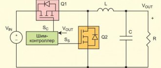
Above is a block diagram of the operation of a multimeter or tester in resistance measurement mode. As you can see, a DC voltage of a certain polarity is supplied to the terminals. It is customary to apply the plus to the red terminal, and the minus to the black. When you touch the diode terminals in such a way that the positive output of the device is on the anode terminal of the diode, and the negative output is on the cathode of the diode, then current will flow through the diode. If the probes are swapped, the diode will not pass current.
A diode can usually have three states - good, broken or broken. During a breakdown, the diode turns into a piece of wire; it will pass current no matter the order in which the probes touch. If there is a break, on the contrary, the current will never flow. Rarely, but there is another condition when the transition resistance changes. Such a malfunction can be determined by the readings on the display.
Using the above instructions, you can check rectifier diodes, zener diodes, Schottky diodes and LEDs, both with leads and in SMD version. Let's look at how to test diodes in practice.
First of all, it is necessary, observing the color coding, to insert the probes into the multimeter. Usually a black wire is inserted into COM, and a red wire into V/R/f (this is the positive terminal of the battery). Next, you need to set the operating mode switch to the dialing position (if there is such a measurement function), as in the photo, or to the 2kOm position. Turn on the device, close the ends of the probes and make sure it is working.
We’ll start the practice by checking the ancient germanium diode D7, this specimen is already 53 years old. Germanium-based diodes are now practically not produced due to the high cost of germanium itself and the low maximum operating temperature, only 80-100°C. But these diodes have the smallest voltage drop and noise level. They are highly valued by tube amplifier builders. In direct connection, the voltage drop across a germanium diode is only 0.129 V. The dial tester will show approximately 130 Ohms. When the polarity is changed, the multimeter shows 1, the dial tester will show infinity, which means a very high resistance. This diode is OK.
The procedure for checking silicon diodes is no different from checking those made of germanium. The cathode terminal is usually marked on the diode body; it can be a circle, line or dot. In direct connection, the drop across the diode junction is about 0.5 V. For powerful diodes, the drop voltage is less, and is about 0.4 V. Zener diodes and Schottky diodes are checked in the same way. The voltage drop of Schottky diodes is about 0.2 V.
For high-power LEDs, more than 2 V drops at the direct junction and the device can show 1. But here the LED itself is an indicator of serviceability. If, when turned on directly, you can see even the faintest glow of the LED, then it is working.
It should be noted that some types of high-power LEDs consist of a chain of several LEDs connected in series and this is not noticeable from the outside. Such LEDs sometimes have a voltage drop of up to 30 V, and they can only be tested from a power supply with an output voltage of more than 30 V and a current-limiting resistor connected in series with the LED.
Continuity of wires
In the continuity mode, you can check the wires for breaks in any part of the circuit. On the multimeter scale it is indicated by the “sound mixer” icon. If the wiring and contacts are intact, a signal will be heard - a subtle squeaking sound. If there is no conduction, the sound stops.
How to find out if the wires are intact:
- Select the dialing mode with the switch.
- Insert the probes into the COM base and the middle VΩmA connector.
- Touch the contacts of the area under study with a multimeter, closing the circuit.
Based on the presence or absence of sound, conclusions are drawn about the integrity of the wires. It is recommended to pre-ring the probes themselves to prevent damage. They are connected by tips to each other, and a continuous sound should be heard.
Visual check of the resistor condition
Before checking the resistor with a multimeter, you should inspect it. In this case, you need to pay attention to the presence of the following signs:
- There is noticeable darkening on the body. If the darkening is slight, this indicates slight overheating, at which the part can remain operational.
- The appearance of a specific odor.
- The markings become faintly visible.
- Burnt tracks are visible on the board.
If there is obvious damage, the faulty part should be removed and a resistor with the same value installed in its place. If the resistance appears to be working outwardly, it is necessary to check for serviceability using a multimeter.
How is insulation testing done?
This procedure is performed only in rooms with positive temperatures or in warm weather. This is due to the possibility of ice crystals appearing in the inner part of the cable braid. Such formations are classified as non-conductive dielectrics. Testers simply do not take them into account, but after thawing, the moisture that appears has a negative effect on the condition of the cable.
Digital multimeter models have several sections, which can be selected manually. The required measurement limit is selected after an approximate assessment of the parameters of the circuit being tested. The most popular modifications T83x, M83x, MAS83x are equipped with five testing options.