Safety during installation and repair of electrical installation devices must be ensured by all possible means. It is necessary to exclude both light shocks and severe electric shocks. Do you agree? Before performing any actions with electrical points, it is necessary to check the voltage, which is done using a multimeter.
We will tell you what this portable device is and how it works, used by both home craftsmen and professional electricians. Here you will learn how to check the voltage in an outlet with a multimeter, as well as whether there is voltage in the network itself. Let's look at how it can be used to measure current strength.
For you, we have described in detail the types of multimeters and given the rules for their use. To optimize the perception of a difficult topic, we included photo collections, diagrams, and videos.
Household power supply
Considering the topic and specifics of the article, we are talking about the metric measurement of a household power supply network. But to carry out work to determine the parameter values, it is necessary to have at least an approximate understanding of the characteristics of the household electrical power supply network.
And the socket, in this case, acts exclusively as an “output point” for voltage, so it is reasonable that you need to know what voltage in the socket the consumer will “work” with.
All over the world, there are several main categories of electrical power networks for household electrical appliances, one of which is “our” 220 V with a frequency of 50 Hz. It consists of two wires (“phase” and “zero”), the voltage between which is 220 V.
Recently, for supply systems for private houses and apartments, a 3-phase voltage network of 380 V with a frequency of 50 Hz is sometimes connected to “power” devices such as a pumping station, compressor, lathe, etc.
The household electrical network “provides” 220 V (single phase) voltage in sockets for current foreign and domestic household appliances: from kettles and hair dryers to dishwashers and washing machines
A natural question arises: why is it necessary to measure network characteristics? On the one hand, the answer is obvious: if you do not know or are not confident in your beliefs regarding the outlet that you see in front of you and you need to do some work with the wiring.
On the other hand, most electrical appliances are precisely designed for a specific frequency and voltage. Some electrical devices are designed to operate from a 60 Hz power supply.
For example, an imported microwave oven made in South Korea is equipped with a transformer, which can easily “swell” from “our” 50 Hz and it (the oven) will quickly fail.
Exceeding or decreasing frequency, voltage and current can significantly change the efficiency of devices, as a result of which the electrical device fails and subsequent operation is impossible. Multimeters are needed to measure and monitor such network parameters.
Multimeter scale markings
Analog instruments with arrows have scales, which are divided into named and conditional. Named scales are graded with measurable indicators. Conventional scales are used in instruments that are capable of measuring many parameters.
Which wires are best to use for wiring in an apartment. Great comparison article here.
To find a numerical indicator that is measured by a device with a conventional scale, it is necessary to multiply the value of one scale division by the number of divisions on a given scale up to the interval where the arrow appears.
In addition, to determine the value of one division, it is necessary to establish the difference between the indicators of nearby divisions with numbers and divide by the number of divisions between them.
Multimeter markings
The positions of the linear or angular intervals between the surrounding scale marks, and the measured indicators, are distinguished by devices of uniform and non-uniform types.
What to do if a person is electrocuted? Everyone should know this, everyone should read it!
For accurate results, a model with a uniform scale is preferred. This scale will be uniform if the ratio of the largest number to the smallest does not exceed the reading of 1.3 with a constant division value.
Near the scale on the front panel of the measuring device, the existing marking parameters are listed:
- measure of value;
- GOST, according to which the multimeter is manufactured;
- tester device; degree of protection of the device from the influence of external magnetically active and electrical environments;
- accuracy class.
In addition, it is indicated:
- tool category according to operating requirements;
- functional location of the multimeter;
- number of phases and type of current;
- experimental voltage for the reliability of electrical insulation of current-carrying elements of the invention;
- the location of the tester in comparison with the earth's magnetic field;
- the year of publishing;
- view;
- code;
- factory number and other indicators.
Safety precautions before work
A multitester is a multifunctional portable device that is powered by a battery (usually a crown) and is a convenient, and most importantly safe, tool for the end user. But for its operation there are certain rules of use.
“Krona” is a battery of galvanic batteries, overall dimensions 48.5X26.5X17.5 mm. The battery weight is about 53-55 grams. Output voltage - 9 V, average capacity - 600 mAh
The tester itself is equipped with internal protection against overloads and overvoltages. But without following the rules below, it can also easily “burn out” and partially fail. To avoid this, there are a number of general rules for the safe operation of a digital tester.
When measuring AC input voltage:
- If the preliminary value of the measured voltage has not been determined, set the switch to the largest range.
- Do not apply voltage more than 750 V to the input to avoid damaging the internal circuit.
Hands without dielectric gloves should not touch electrical components.
When measuring DC and AC input current:
- If the preliminary value of the measured current has not been determined, set the switch to the largest range.
- If the LCD display is set to “1”, set the trigger to the next range in the direction of increasing the maximum value.
- When working with the “20A” connector, the testing time should not exceed 15 seconds, since there is no fuse for this mode.
When measuring the internal resistance of a circuit, you need to make sure that the power to the circuit is turned off and all capacitors are discharged to zero.
The fuse is a glass bulb with external metal contacts in the form of “caps”. Inside the flask there is a piece of wire that melts at the moment of overload; it opens the circuit and saves the device from breakdown
In addition, there are special rules for the care and storage of the device, namely, you do not need to apply voltage to the input if the rotary switch is in the Ohm position, and work with the device if the housing cover is not completely closed. And lastly, replacing the galvanic battery and fuse is carried out only with the device turned off and the probes disconnected.
Typical measurements with a household multimeter
DC current measurement
Measurement of direct current of safe value. For example, checking a car battery. Mode setting: DC voltage measurement. The measurement limit is 20 volts (closest range). The measuring cables are connected in accordance with the instructions.
How to check batteries or accumulators
We check AA batteries or accumulators in a similar way. The measurement limit in our case is the same 20 volts DC voltage. The estimated value is 1.4 volts. We press the contacts to the battery (observing polarity) and take readings.
Hazardous Voltage Measurement
Attention! Only persons with the appropriate clearance groups may work with dangerous voltage!
Measuring dangerous voltage: for example, in a socket network. First, let's check the measuring cables. The insulating handles must be intact and the wires must be securely held. Restrictive rings are molded onto the measuring cable to prevent fingers from slipping into the danger zone when pressing against the contacts being measured.
We set the AC current measurement mode, the measurement limit is 500 (or 750) volts (measured voltage 220 volts). We securely fix the cables in the device, connect to the outlet, manipulating with one hand.
To measure the voltage in the network, a few seconds are enough. Do not leave the device connected to the outlet for a long time.
Chain continuity
Having figured out how to use a voltage tester, we move on to the simplest operation: checking the continuity of the circuit.
Attention! It is permissible to perform testing only on completely de-energized sections of the circuit.
This is done when such a mode is available on the device.
Before starting the dialing, we connect the probes to each other and check the functionality of the device (a stable sound signal). If the ends of the wiring being tested are far apart, use an extension cord.
Important! To allow you to safely work on mains wiring in test mode, you must physically disconnect the line being tested at the nearest junction box.
Checking radio components
Of course, parts should be checked after they are removed from the circuit board. As a last resort, it is enough to disconnect one contact.
Checking a diode or resistor . We set the appropriate mode on the switch. If you do not know the approximate value, we start measuring from a higher limit. By switching the measurement range, you will sooner or later find the desired value.
LEDs are checked in dial mode. Even if you see that the diode is properly conducting current in one direction (in the test mode for conventional diodes), but does not light up, the measurements do not matter.
In dialing mode, the current will be sufficient to ignite the crystal. Reversing the polarity will not damage the part. The diode just won't light up.
You need to know this: Even economy class testers have some overload protection and a fuse on the input contacts.
But this does not mean that you can confuse the modes and connect to a high voltage with a low measurement threshold set.
How to check grounding
Grounding measurements can also be made using a household tester.
- First of all, let's make sure that you have a ground connection in your house . To do this, open the housing of any outlet and carry out a visual inspection. If nothing is connected to the “ground” contact, or there is a jumper (this is dangerous!) between the zero and “ground” terminals, there is actually nothing to check. If there is a “ground” on the contact: a typical yellow-green wire, you can check whether “natural grounding” is connected, or whether you have a combined neutral and ground bus.
- Determining the phase. There is an indicator screwdriver for this.
- Then, having previously checked the wires and set the correct mode, we measure the voltage between the phase and the neutral contact . We record the result and take a measurement between the phase and the ground being tested.
- If the result of step 3 is the same, then you have a false “ground” , the wire is combined with the zero bus. This is extremely dangerous; it is better to disconnect such a wire altogether and cover it with an insulating cap.
- If the result of step 3 differs by several volts, check several times with the minimum possible measurement interval. With a stable difference in value, you can be confident in the safety of your electrical network. You are naturally grounded .
How to check grounding without an indicator screwdriver
To do this, you need to use a tester to check the voltage between all pairs of contacts. Of course, this makes sense if there is a wire connected to the ground pin of the outlet.
A voltage close to 220 volts will only be between the pairs: phase-zero and phase-ground. It is clear that the phase cannot be connected to the grounding contacts of the socket; therefore, it is in one of the working holes.
You already know how to use a tester to check natural grounding (with a known phase contact).
Multimeter symbols
In fact, the multitester consists of several standard parts: a display (in analog – a scale with protective glass), a multi-position rotary switch, connectors for connecting probes. In this article, the DT9205A model is considered as a multimetric device.
The digital multitester DT9205A has extensive capabilities, including measuring AC and DC voltage and current, resistance, capacitance, and diode health. Size - 186x86x41 mm, weight - 318 grams
Buttons:
- ON/OFF—turn on/off the device;
- HOLD - Holds the displayed value on the LCD screen.
Central switch sectors:
- hFE – measurement of transistor parameters;
- F, Ω - testing capacitor capacity and resistance;
- A-, A~ - direct and alternating current;
- V-, V~ - constant and alternating voltage.
Main connectors:
- 20A - socket for measuring current up to 20A, red probe;
- A - socket for testing current strength within ranges;
- COM - socket for all modes, usually a black probe is connected;
- VΩ - socket for measuring resistance and voltage.
Section connectors “pnp/npn” - semiconductor testing, “cx” - connectors for inserting the capacitor being tested. It is imperative to observe the polarity, otherwise it will “swell.”
In order to use a multitester correctly, you should know what functions it has. Buttons indicating functions are located on the front panel (+)
Connecting probes to a multimeter
Probes are a special type of connectors that help measure the characteristics of electrical parts and sections of a wire circuit. They easily connect the necessary connectors of the multitester with other outputs.
Usually they are a metal rod with plastic insulation, at one end of which the rod exits from the other - a wire with a connector for insertion into the 20A, A, COM and VΩ connectors of the device.
In addition, sometimes it is necessary to have an additional set of probes in your arsenal, but instead of a rod, metal “crocodiles” are used - toothed clamps.
“Crocodile” is a special type of attachment for multitester probes, very convenient for measuring the electrical characteristics of medium and large parts
Most devices are imported from China, where they are manufactured in factories, workshops and mini-workshops. In this regard, manufacturers save on everything, including materials for probes, which quickly fail.
It is recommended to make the probes yourself by purchasing parts on the radio market or in a radio store. Instead of insulating plastic, empty ampoules and casings for ballpoint pens are often used.
The COM connector is an electrical “minus” and performs the grounding function in all modes and ranges. Usually a black probe is connected here
We connect the plug of the black probe into the multimeter connector marked COM. And we connect the plug of the red probe into the connector marked VΩ, which is designed for measuring direct and alternating voltage.
We strongly do not recommend pressing the red and black probes onto the contact in any mode, with the exception of the rotary switch in the “►” position (chain continuity).
In addition to voltage, the multitester can measure current and resistance values. It is important to remember that when measuring resistance values, you must turn off the power
How to measure current with a multimeter on a battery
Any machine has its own minimum amount of current leakage, which varies, in amperes, from 0.01 to 0.08. First, it’s worth understanding the causes of current leakage in the car. One of them may be that the owner simply forgot to turn off the lights, for example.
There are cars that have a bad factory design built into them. This can be considered a glass heating system, which conducts its power chain bypassing the ignition switch. Let’s not forget about children who love to sit in the driver’s seat, turning various instrument levers.
The second global reason may be an incorrect connection. Thus, during the period of global interest among car enthusiasts in music and radios, the battery charge was melting before our eyes. This happened because the installers did not know how to connect the devices correctly. One ignition wire passed through the ignition switch did the job. If you have an anti-theft system installed, and the next morning you find an empty battery, then there is no need to guess.
We also advise you not to leave recorders, radars and other devices in cigarette lighters and sockets. Not all cars provide them when the ignition is not working.
In order to determine current leakage, you need to perform some steps. So, with the hood open, unscrew the negative terminal from the battery. Next, after removing it, set the multimeter to amperage mode. Place a probe into the gap between the terminal and the battery contact. Numbers appear on the display that reflect the amount of leakage. If you see the readings in mA, then you can rest assured. If the measurements are presented in amperes, then hurry to take certain measures.
Measuring AC voltage in a socket
Introductory and preparatory work has been completed. Let's move on to the actual execution of the task. First of all, turn off the multitester if it is turned on. Press the ON/OFF button.
We move the rotary trigger of the multimeter to the “750” position (in other testers it can be 600, 1000) of the “V~” section. This means that the device can measure AC voltage parameters ranging from 0 to 750 V.
If we set the range below the rated desired voltage (less than 200 V), we can damage the device, thus creating an overvoltage situation. In the best case, you will have to change the fuse, in the worst case, you will have to “use” the multitester for spare parts
We turn on the tester, at least one “zero” should appear on the liquid crystal screen - the device is ready for use. We insert the probes into the holes of the socket one by one, it doesn’t matter which one goes where. We take readings of the alternating current of the household power supply network.
The values on the screen jump and do not show exactly 220V - this is normal, because we are dealing with a single-phase network with alternating voltage
Work on testing the power supply network must be carried out quite carefully, slowly and without touching the exposed parts of the probes.
Measuring current in a socket
Never, under any circumstances, measure the AC power of an outlet with a multitester directly, without a connected load. If you simply insert two probes from the tester into the socket, you can “say goodbye” to the device. As a result, we get “New Year’s fireworks” and a burnt-out electrical measuring device.
The current strength in a regular socket must be measured with a load connected in series to the “tester-socket” circuit. Even an ordinary light bulb with a socket (the place where the lamp is screwed in) can act as an elementary load.
To correctly measure the current in the circuit, we switch the trigger to the maximum position of the “A~” section; in the presented device this value is 20 Amperes. We move the red probe into the connector labeled “20A” (UNFUSED - mode without a fuse, FUSED - mode with a fuse)
Having connected the tester and the light bulb in series, insert one of the probes into the socket, and connect one wire from the light bulb base to the other probe. We insert the second wire of the light bulb into the free hole of the socket. We take the current values. It is not recommended to measure for more than 15 seconds in time.
And yet, it is not recommended to measure current strength in an outlet. This does not carry any semantic load. The household power supply simply has a maximum limit in Amperes that must be observed. The current strength always exists only in the presence of a load, where we measure the current.
Why do you need to measure current?
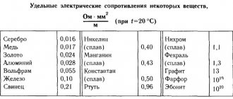
The voltage and resistance of the electrical circuit, which are measured in units such as volts (V) and ohms, respectively, have a significant impact on the amount of current. In this case, an increase in voltage with a constant resistance of the electrical circuit causes an increase in current strength, and an increase in the resistance of the circuit with a constant voltage value leads to its decrease. Current (I), voltage (U) and resistance (R) depend on each other and are related by empirical formulas:
- I = U/R
- U = I*R
- R = U/I
In this case, it is simplified to assume that a current of 1 A appears in a conductor with a resistance of 1 Ohm if a voltage of 1 V is applied to it.
Current measurement
By measuring the CT with a multimeter, you can:
- clarify the actual power consumption of a particular electrical appliance;
- find defects in an electrical appliance if its actual power does not correspond to the value stated in the documentation;
- find out the electrical capacity of autonomous power sources (batteries, etc.);
- identify the existence of current leakage in electrical circuits and, if necessary, localize the defective area;
- check the battery charger to ensure that the charging current corresponds to the specified value, etc.
Such measurements are carried out using special instruments - ammeters. There are enough varieties of them on the domestic market to satisfy the needs of all buyers.
The most popular, especially at the household level, are small multifunctional (ammeter + ohmmeter + voltmeter) multimeters, with which you can measure almost all the necessary parameters of an electrical circuit.
Conclusions and useful video on the topic
The video will clearly demonstrate the sequence of actions when taking measurements in dynamics:
The article clearly explains how to measure voltage and current in an outlet for everyone who knows and is just getting acquainted with electrical outlets and electrical wiring. Using a multimeter will significantly reduce the likelihood of dangerous situations occurring when installing and repairing wiring, replacing sockets and switches.
Do you have some interesting information to share about using a multimeter? Did you have any questions while reading the article? Please write comments in the block intended for feedback.