TYPES AND TYPES PARAMETERS AND CHARACTERISTICS
Power supply (PSU) is an electrical device that performs the function of converting primary voltage (electrical network, battery) into the value required for the operation of various types of equipment:
- heating boilers;
- welding machines;
- LED strips;
- computers, televisions, etc.
The most common version of the power supply involves converting 220 Volts of alternating voltage (U) into a reduced direct voltage.
In addition, power supplies can provide galvanic isolation between input and output circuits. In this case, the transformation ratio (the ratio of input and output voltages) can be equal to unity.
An example of such use would be to supply power to areas where there is a high degree of electrical hazard, such as bathrooms.
In addition, quite often household power supplies can be equipped with built-in additional devices: stabilizers, regulators. indicators, etc.
What is a computer power supply and what is it responsible for?
Computer components do not consume alternating current from a 220-volt network. To power them, they need a constant voltage of different levels (from 3.3 volts to 12 volts), this level must be stable, without drops. They also need overcurrent protection in the event of a fault. All these functions are performed by the power supply. Its main purpose:
- converting AC network voltage into several DC voltages;
- stabilization of output voltages regardless of changes in mains voltage and changes in load currents.
The power supply also provides control functions:
- supplies power to the section of the motherboard responsible for starting the PC;
- starts when receiving a signal from the computer;
- monitors the presence of all output voltages and, if absent, generates a corresponding signal.
The power supply is an important component of a computer or server. If without some components a computer system can work and, at least in a reduced mode, function (without a CD-ROM drive, without a network or sound card, even without a keyboard or mouse), then without a power supply it will not even start.
Load distribution and possible malfunctions
The voltage supplied by the power supply is designed for different loads. Thus, depending on the configuration of a particular PC, the power consumption in each power supply circuit may vary . That is why the technical characteristics of the power supply indicate not only the total power of the device, but also the maximum current consumption for each type of output voltage.
When upgrading PC hardware, you should remember this fact. For example, installing a powerful modern video accelerator leads to a sharp increase in the load in the 12 V circuit. For the PC to work correctly, it may be necessary to replace the power supply. Most often, problems with the operation of a power supply are associated with aging of its design elements or a significant lack of power.
Do not forget that overheating of the output stage may be associated with the accumulation of a large amount of dust inside the power supply. Electrolytic capacitors installed in the mains rectifier and output stages are more prone to aging than other parts.
This primarily applies to products from little-known brands that use cheap components. In fact, it is the element base and quality of parts that distinguishes good devices from cheap ones. Only a person who has a certain set of knowledge in the field of electronics can repair the power supply independently. However, modern devices manufactured by well-known brands are highly reliable. If you follow the PC maintenance rules, problems with them very rarely arise.
What varieties are installed on the PC?
All computer power supplies are built in accordance with the ATX standard. The previous AT standard became obsolete back in the 90s of the last century. The main difference between the switching power supply device of an ATX computer is the presence of a standby voltage, which allows you to turn on the computer without switching the power supply circuits.
The structure of switching power supplies (SMPS), a description of circuit solutions will be given below, and in order to initially navigate the types of power supplies, you need to know the general principles of device classification.
First of all, SMPS for computers are divided by power, and in parallel with the development of PCs, this parameter is constantly growing. If 20 years ago a power supply with a power of 250 watts was enough to cover any needs, then at the moment 550 watts is not always enough.
Also, many people pay attention to the presence of an 80PLUS certificate, which means increased efficiency of the power supply. From a technical point of view, this is important, but from an economic point of view, one must understand that the difference in cost will compensate for the gain in electricity no sooner than in several decades. Although there is one more point - power supplies certified to the highest categories 80+ (Gold, Titanium, etc.) do not have a fan, which means practically silent operation. The other side of the coin is that fanless power supplies are often made with an external heatsink that protrudes beyond the dimensions of the PC case. This may cause problems with your computer installation.
Exits
All power supplies come with long bundles of wires sticking out from the back. The number of wires and available connectors for powering devices will vary from model to model, but some standard connections should be provided by all power supplies without exception.
Since voltage is the magnitude of the potential difference, each output has two wires: one for the specified voltage (for example, +12 V) and a wire against which the potential difference is measured. This wire is called the ground, "earth", "reference wire" or "common" wire, and these two wires form a loop: from the power supply to the consumer device, and then back to the power supply.
Because some of these closed loops carry small currents, they may share common ground wires.
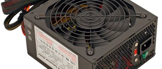
Official photo of the Cooler Master power supply.
The main required connector is the 24-pin ATX12V v. 2.4, which provides main power via several pins of different voltages, and also has a number of special pins.
Of these special ones, we note only the “+5 standby” pin – standby power supply for the computer. This voltage is always supplied to the motherboard, even when the computer is turned off, provided that it remains plugged in and its power supply is working. The motherboard needs standby power in order to remain active.
Most PSUs also have an additional 8-pin motherboard connector with two +12V lines, and at least one 6 or 8-pin power connector for PCI Express.
The PCI Express slot can handle a maximum of 75W of graphics cards, so this slot provides additional power for modern GPUs.
Our particular power supply in question actually uses two PCI Express power connectors on the same lane for cost reasons. Therefore, if you have a really powerful video card, try to allocate an independent power line for it, do not share it with other devices.
The difference between 6 and 8-pin PCI Express connectors is two additional ground wires. This allows you to increase the current, satisfying the needs of the most power-hungry video cards.
Over the past few years, we have increasingly begun to notice power supplies proudly labeled “modular” (modular PSU). This simply means that they have detachable cables, allowing you to use only the number of cables and connectors you need without connecting anything unnecessary, thereby freeing up space inside the unit.
Photo source nix.ru
Our Cooler Master, like most, uses a fairly simple system for connecting modular cables.
Each connector has one +12V, +5V and +3.3V wire, as well as two ground wires, and depending on what device the cable is connected to, the connector at the other end will use either the corresponding or simplified wiring.
The Serial ATA (SATA) connector pictured above is used to connect power to hard drives, solid-state drives, and peripherals such as DVD drives.
This familiar connector is called intricately: “AMP MATE-N-LOK power connector 1-480424-0”. But everyone simply calls it Molex, despite the fact that this is just the name of the company that developed this connector. It provides one +12V and +5V terminal, and two ground wires.
On output wires, manufacturers can also save money or increase the price by using brighter or softer wires. The cross-section of the wire also plays an important role, since thicker wires have less resistance than thin ones, so they heat up less when current passes through them.
Functions and principle of operation of the main components
Block diagram of a computer power supply.
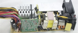
Power supplies in computers are made using pulse circuits. Their main advantage is their small size and weight with high power. The disadvantages are also known - complex circuitry and, as a result, reduced reliability. In general, such sources are repairable, but restoration requires increased qualifications of a technician and the availability of instruments.
When building power supplies, each manufacturer uses its own circuit design solutions, but all SMPS are based on a single operating principle:
- rectification of mains voltage;
- “cutting” high-frequency pulses from it (from several kilohertz to several hundred kilohertz);
- transformation of high voltage into low voltage;
- rectification, subsequent filtering of DC voltages.
Despite the difference in circuits, most supply voltage sources are built according to a standard block diagram and contain the same structural elements. You can consider them using the example of a circuit diagram of a Power Master LP-8 unit with a power of 230 watts.
Schematic diagram of a switching power supply Power Master LP-8 ver.2/03 230 W.
Input filter
PSU input filter circuit.
The input filter is not a critical part of the switching power supply circuit - everything will work without it. But it is impossible to do without filtering circuits - the SMPS will generate interference into the supply network, and the operation of other devices on microcontrollers powered from the same network will become unpredictable. The input circuits contain protection elements against common-mode (unbalanced) interference and differential – symmetrical. The inductor LF1 and capacitors Cy protect against the former. To protect against the latter, a capacitor Cx is installed.
The input circuits also contain a thermistor RTH1 - in a cold state it has a high resistance and limits the charging current of the capacitors of the high-voltage rectifier. After warming up, its resistance drops and it does not affect operation.
The circuit contains fuse F1, which protects the power supply from short circuits. This inclusion of the fuse link is not optimal - elements RTH1, Cx2, LF1 are unprotected. A different input circuit diagram looks better.
Improved protection scheme.
There is one more element here - a varistor. In the normal state, its resistance is high, it does not affect the operation of the power supply. But when the mains voltage surges, it opens, its resistance drops, and the current through it contributes to the fuse blowing.
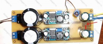
High voltage rectifier and smoothing filter
Rectification circuit with filter capacitor.
The DC voltage generation circuit does not contain any special features. It consists of a full-wave bridge rectifier on a diode assembly and a smoothing filter. The capacitors are connected in series - this is how the divider is made to obtain half the supply voltage required to operate the half-bridge inverter.
Pulse generator
Pulse generator on TL494.
The pulse generator that controls the inverter is made on a TL494 microcircuit in a standard connection. It is a pulse width modulation (PWM) controller. The average open time of the inverters (and therefore the output voltage) is controlled by adjusting the duration of pulses that follow at the same frequency. It is set by resistor R53 and capacitor C27.
Pin 4 is supplied with voltage from the signal processing circuit PS_ON (Power_ON). If there is a low voltage at this pin, the microcircuit begins to generate pulses and the power supply starts.
Feedback on the output voltages is organized through pin 1 - if the voltage of the computer power supply decreases, the pulse width increases and vice versa (all channels are adjusted simultaneously). Current feedback is not used in this circuit, so this source does not have overload protection. A high level is applied to pin 13 from pin 14, this determines the operating mode of the microcircuit - push-pull. The generated pulses are removed from the output transistors - pins 8,9 and 11,10.
We recommend: How to make your computer turn on automatically when power is applied
Inverter
Half-bridge inverter circuit.
The task of the inverter is to transform the rectified DC voltage into a unipolar pulse voltage suitable for transformation (similar to a bipolar alternating voltage). The transistors open and close in turn, applying a voltage of about 300 volts to the primary winding of the transformer.
In this case, the inverter is assembled using a half-bridge circuit - a compromise between bridge and push-pull. This circuitry is used in most power supplies for computers. Since powerful current pulses with good squareness are required to open key transistors Q1, Q2, they are controlled not directly from the pins of the microcircuit, but through a pre-amplifier (driver). It is assembled on transistors Q7, Q8, connected to the final stage via transformer T2. In this source, bipolar transistors are used as switches; in others (especially with a power of 400+ watts), field-effect or IGBTs can be used, combining the advantages of bipolar elements and MOSFETs.
Control circuit and generation of service signals
This scheme usually consists of several independent sections. The Stand By voltage is generated using a separate generator powered by rectified mains voltage. The generator is loaded onto the primary winding of the transformer. The standby power supply itself is removed from the first secondary winding (1-2), straightened, and stabilized by the linear regulator L7805. The second (3-4) removes the voltage for its own needs - powering the PWM chip, as well as the key driver. After starting the SMPS, the +12 volt voltage from the corresponding output channel through diode D12 turns off diode D18, and further power supply to these circuits comes from the output voltage.
StandBy power conditioner.
The PG (Power Good) signal is generated by the specified section of the circuit in the presence of all supply voltages. If everything is ok, a high level is issued to the motherboard. If a channel disappears, the voltage at the output of the driver drops to zero, which serves as a command to turn off the computer.
Formation of the Power Good signal.
The PS_ON signal is issued by the motherboard, closing the green wire of the power supply unit to the common bus. In this case, a low level appears at the emitter of transistor Q13, which, through diode D26, allows the operation of the PWM driver chip.
Scheme for enabling the start of the control pulse generator.
It's not the zener diode
We check whether the short circuit in the duty and ground circuits has been eliminated or not. Indeed, the short circuit has disappeared. I went to the radio store to get a new zener diode and soldered it. I turn on the power supply, and... I see how my new, just purchased zener diode emits magical smoke)...
And then I immediately remembered one of the main rules of a repairman:
If something burns out, first find the reason for it, and only then replace the part with a new one or risk getting another burnt out part.
Cursing to myself, I bite the burnt zener diode with side cutters and turn on the power supply again.
That’s right, the duty is too high: 8.5 Volts. The main question is spinning in my head: “Is the PWM controller still alive, or have I already burned it safely?” I download the datasheet for the microcircuit and see the maximum supply voltage for the PWM controller, equal to 16 Volts. Phew, looks like it should pass...
Nice bonuses
One of the most pleasant “features” of modern power supplies is the modular design: some of the wires (and sometimes all the wires) have connectors at both ends, allowing you to remove unnecessary and unused “braids” from the system unit: it is both more aesthetically pleasing and it is more convenient to lay cables inside the PC , and less resistance to air flow in the housing.
Of course, you have to pay extra for this feature, albeit a little. If you are assembling a computer and your budget is very limited, you can not bother with “modulars” and just take an inexpensive, high-quality model with “built-in” wires, and you will always find somewhere to invest the extra 500-600 rubles.
Peculiarities
It's no secret that modern power supplies (PSUs) have become more powerful, have improved characteristics and, of course, a modern design than their predecessors 10-15 years ago. Also, many of you know (or are learning now) that modern power supplies have new connectors for components not previously used in personal computers (PCs). The presence of new connectors is associated with the emergence of new (or modernization of old) computer components, improvements in their performance characteristics and, as a result, the need for additional power.
On the market, in addition to conventional ones, you can find modular or partially modular power supplies. A distinctive feature of a modular one from a regular one is that the cables from the block are replaced with connectors for connecting cables with connectors. So, you can disconnect unused cables in the power supply, freeing up space in the system unit for better ventilation.
A modern power supply meets energy efficiency and efficiency certification standards that are used to distribute power and efficiently deliver power to computer components. Due to the “greater gluttony” in power supply of the same video cards and motherboards, the power supply contains additional wires, contacts and connectors.
Recommended Models
Among the simple, reliable and unremarkable power supplies, we can mention the FSP ATX-550PNR.
It is inexpensive (less than three thousand rubles), well assembled, does not make noise, has a two-year warranty and is extremely rarely found in service centers. The power supply power is 550W, which is quite enough for a completely typical system unit (like the one we “assembled” a couple of paragraphs above). A slightly more expensive model (but with an efficiency class of 80+) is the Chieftec GPS-550A8, which looks nicer and is quieter.
If, after all the calculations, you have come to the conclusion that you need a power supply with a power of 600-650 W, you should pay attention to the CoolerMaster G650M model. It has 80+ Bronze certification, a good cooling system, supports automatic fan speed control, a modular cable connection system, and costs just over five thousand rubles. The model is new, but it enjoys exceptional success in the “iron” press and among enthusiasts. By the way, it also exists in a 750-Watt version.
An alternative to Cooler Master in the segment of powerful power supplies for top-end computers can easily be called the Corsair CX 750 M. It has all the same advantages as the CM G650M - modular design, 80+ Bronze certificate and an excellent reputation. In addition, the price is not too bad - our Corsair costs a little less than seven thousand rubles.
Well, you can safely forget about all sorts of monsters, such as the Corsair CP-9020008-EU at 1.2 kW. If you don’t have 4 video cards for 30-40 thousand rubles each, then you definitely won’t need such a monster for ~20 thousand rubles.