VGT-UETM®-110
Switches VGT-UETM®-110, VGTZ-UETM®-110 are designed for switching electrical circuits in normal and emergency modes, as well as operating in automatic reclosure cycles in three-phase alternating current networks with a frequency of 50 Hz and a rated voltage of 110 kV.
- The switches are manufactured in climatic versions U and HL*, placement category 1 GOST 15150-69 and GOST 15543.1. They are designed for use in open and closed switchgear in areas with moderate and cold climates
- The lower operating value of the air temperature surrounding the circuit breaker is: for version U1 – minus 45 °C when filling the circuit breaker with SF6 gas, for version HL1* – minus 55 °C when filling the circuit breaker with a gas mixture
- The upper operating temperature of the air surrounding the switch is +40 °C
- Upon request, it is possible to supply it in climatic version T1 – upper operating air temperature +50 °C
- The switch is controlled by a spring drive, with an electric motor for winding springs and various versions of the motor supply voltage
- For closed switchgears there is a special version VGTZ-110 with a reduced overall length for installation in a six-meter switchgear cell
- High factory readiness, simple and quick installation and commissioning
- The natural level of leaks is no more than 0.5% per year
- Possibility of disconnecting load currents in the event of loss of excess gas pressure in the circuit breaker
- Maintaining the electrical strength of the circuit breaker insulation at a voltage equal to 1.15 times the highest phase voltage in the event of loss of excess gas pressure in the circuit breaker
- Switching off capacitive currents without repeated breakdowns, low overvoltages
- Low noise level when activated – meets high environmental requirements
- Possibility of supplying a switching resource metering device or a synchronous circuit breaker control device with a switching resource metering function (for single-pole design).
- Possibility of supplying a distribution cabinet (for single-pole design).
Delivery examples
Technical documents
Questionnaire
Catalog VGT-UETM®-110
Declaration of Conformity
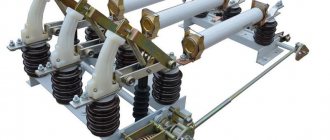
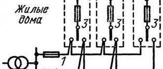
Combined installation of TRG-110 and column switch VGT-110
www.uetm.ru
Purpose of high-voltage circuit breaker VGT-220
Designed to perform switching operations (closing and shutting down), as well as automatic reclosure cycles under specified conditions in normal and emergency modes in three-phase alternating current networks with a frequency of 50 Hz and a rated voltage of 220 kV with a grounded neutral.
SF6 circuit breakers are designed to operate under the following conditions:
Climatic factors of the external environment are normal values in accordance with GOST 15150 and GOST 15543.1 for climatic version U placement category 1, with:
- environment – not containing chemically active and explosive impurities (type II atmosphere according to GOST 15150);
- operating ambient temperature range:
- upper – plus 40⁰C,
- lower – minus 45⁰C;
- relative air humidity at a temperature of 20⁰C – 80% (upper operating value – 100% at 25⁰C);
- the highest installation altitude above sea level is 1000 m;
- wind speed:
- in conditions where there is no ice – no more than 40 m/s,
- in icy conditions with an ice crust thickness of up to 20 mm - no more than 15 m/s;
- intensity of seismic impact: no more than 9 points according to MSK-64.
The switches are not intended for switching the shunt reactor and capacitor banks. The switches comply with the requirements of GOST R 52565 “AC switches for voltages from 3 to 750 kV. General technical conditions".
SF6 core switch VGP-110
SF6 core switch VGP-110 (Electroapparat VO, JSC)
Specifications:
TU3414-019-046821485-2006
Since 2006, serial production of VGP-110 column switches has been resumed. The traditions of the St. Petersburg school of apparatus engineering, reflected in the VGP-110 switch, take into account, first of all, the specifics of operation in Russian conditions:
The arcing device has several modifications in terms of switching capacity for networks with different short-circuit currents, for different minimum operating temperatures.
The internal insulation is formed under reduced pressure of SF6 gas for operation at low ambient temperatures without the use of mixtures.
The mechanical life of the drive is 10,000 O–V operations; the mechanical life of the switch phase has no restrictions within the framework of reasonable operation during its service life.
Resistance to any influence of the external environment is ensured by protective coatings for the entire service life.
The safe operation of switching devices, like pressure vessels, is ensured by a protective device.
The stability of production quality is confirmed by periodic tests of serial products, including switching tests, at the Test Center of JSC NIIVA.
| Parameter name | Unit change | Execution | |
| VGP-110-40 U1 | VGP-110-20 UHL1* | ||
| Rated voltage | kV | 110 | 110 |
| Highest operating voltage | kV | 126 | 126 |
| Rated current | A | 2500 | 2500 |
| Rated breaking current | kA | 40 | 20 |
| Parameters of through short circuit current: - largest peak - thermal resistance current - flow time of thermal resistance current | ka ka s | 102403 | 102403 |
| Current of unloaded lines, disconnected without repeated breakdowns | A | 31,5 | 31,5 |
| Own shutdown time | With | 0,03 ±0,005 | 0,03 ±0,005 |
| Total shutdown time | With | 0,05… 0,055 | 0,05… 0,055 |
| Minimum no-current pause during automatic reclosure | With | 0,3 | 0,3 |
| Own switching time | With | 0,6 ±0,2 | 0,6 ±0,2 |
| Gas consumption for leaks in % per year of gas mass, no more | % | 1 | 1 |
| Mass of SF6 gas no more than | kg | 6,3 | 4,3 |
| Excessive pressure of SF6 gas, reduced to +20° C13.1. Filling pressure 13.2. Alarm pressure 13.3. Blocking pressure | MPa MPa MPa | 0,40,340,32 | 0,30,240,22 |
| Minimum air temperature | °C | -45 | -50 |
| Switch weight: - with spring drive - with spring-hydraulic drive | kg kg | 15001300 | 15001300 |
| Life time | years | 40 | 40 |
| Guarantee period | years | 3 | 3 |
The SF6 gas column circuit breaker VGP-110 meets the requirements of the following regulatory documents: IEC standards
GOST R 52565-2006 “AC switches for voltages from 3 to 750 kV”
GOST 15150 “Versions for various climatic regions regarding the influence of environmental factors”
GOST 9.014-78 “Unified system of protection against corrosion and aging”
PB03-576-03 “Rules for the design and safe operation of pressure vessels” Certificate of Conformity No. 6791540
The quality system of JSC VO "Electroapparat" complies with the ISO 9001:2000 standard, which is certified by BVQI certificate No. 203351 dated November 13, 2006.
VGP-330
The SF6 column switch is designed for switching electrical circuits and shunt reactors during operating and emergency modes in three-phase alternating current networks with a grounded neutral for a rated voltage of 330 kV.
Each pole of the circuit breaker is a sealed SF6 gas-filled column that has an arc suppressor, a hollow support insulator and a mechanism housing. The three poles of the circuit breaker can be mounted on separate support posts or on a common support frame.
digest.wizardsoft.ru
Gas-filled equipment – CJSC "ZETO"
Purpose
Designed for switching electrical circuits under normal and emergency conditions, as well as operation in automatic reclosure cycles in three-phase alternating current networks with a frequency of 50 Hz and a rated voltage of 110 kV.
Design
The switches consist of three poles (columns) mounted on a common frame and controlled by one spring drive PPrM. Explosion-proof design.
Reduced effort to operate the switch. The energy required to extinguish short-circuit currents is partially used from the arc itself due to the special design of gas flow control units, which significantly reduces the drive load and increases reliability. The use of four stages of seals in conjunction with a hydraulic seal in the rotary mechanism shaft seal assembly ensures a consistently low level of leakage: no more than 0.5% per year.
Modern technological and design solutions in the field of application and processing of materials, the use of reliable components, including high-quality tires from leading foreign companies.
The steel parts of the switch and supporting metal structures have corrosion-resistant coatings.
Switches can be supplied upon request with shortened factory support posts, as well as with or without tall support posts.
Advantages:
- Maintaining the electrical strength of the switch insulation at a voltage of 84 kV in the event of loss of excess gas pressure in the switch.
- Switching off capacitive currents without repeated breakdowns, low overvoltages.
- Low level of audible noise when triggered (meets environmental requirements).
- Low dynamic loads on foundation supports.
- The reliability and safety of the PPrM spring drive is confirmed by many years of experience in controlling column switches.
- The presence in the automatic control drive of two heating stages (anti-condensation and main) of the drive cabinet and monitoring of their serviceability.
- Components are purchased from leading, reputable domestic and foreign manufacturers.
- The block-modular design of the circuit breaker makes it possible to supply the customer with products in convenient containers with a minimum volume at minimal transportation costs, as well as to ensure convenient and prompt installation and commissioning, which are carried out under the guidance of a chief engineer.
Specifications
| Rated voltage, kV: | 110 |
| Maximum operating voltage, kV: | 126 |
| Rated current, A | 2000, 3150 |
| Rated breaking current, kA | 40 |
| Normalized percentage of aperiodic component, % not more than | 45 |
Normalized switching current parameters, kA
| 102 40 |
Normalized parameters of through short circuit current, kA:
| 102 40 3 |
| Rated shutdown current of an unloaded overhead line, A | 31,5 |
| Rated shutdown current of the capacitor bank, A | 320 |
| Own shutdown time, at rated voltage on control elements, ms, no more | 38 |
| Total shutdown time, at rated voltage on control elements, ms, no more | 55 |
| Own turn-on time, at rated voltage on control elements, ms, no more | 60 |
| Normalized dead time during automatic reclosure, s | 0,3 |
| Timing of closing and opening contacts of poles s, no more when turned on when disconnected | 0,0018 0,0015 |
| Specific creepage distance, cm/kV | 2,5 |
| Permissible level of gas leakage per year, % no more | 0,5 |
Gas pressure (SF6), reduced to plus 20ºС, MPa, excess:
| 0,4 0,35 0,32 |
| Rated voltage of on and off coils, V, constant | 220/110 |
Rated supply voltage of the drive electric motor, V, alternating
| 400 or 230 230 220 |
| Current of on and off coils at rated voltage, A, no more | 3/5 |
| Rated supply voltage of heating devices, V, alternating | 230 |
Number of pairs of switching contacts for external circuits:
| 12 12 |
| Switching temperature of heating devices, ºС | 1±1 |
| Weight, kg | 1570 |
www.zeto.ru
SF6 gas switches VGT-UETM series for 35, 110 and 220 kV
Transcript
1 high-voltage equipment Gas-insulated switches of the VGT-UETM series for 35, 110 and 220 kV 1
2 CONTENTS: 1. PURPOSE 2. MAIN ADVANTAGES 3. TECHNICAL DATA 4. DEVICE AND OPERATION 5. DEVICE AND OPERATION OF COMPONENT PARTS 6. OVERALL DIMENSIONS 7. QUESTIONNAIRE - APPLICATION Attention! Due to the constant improvement of the design of equipment produced by our plant, the weight, as well as overall, installation and connection dimensions, as well as technical data may differ from those indicated in the catalog. When designing power supply facilities, these characteristics should be clarified with the manufacturer. If necessary, you can download electrical and dimensional diagrams on the website in the “High-voltage equipment” section. 2
3 1. PURPOSE 1.1. The switches are designed for switching electrical circuits under normal and emergency conditions, as well as operation in automatic reclosure cycles in three-phase alternating current networks with a frequency of 50 Hz and a rated voltage of 35, 110 and 220 kV. The switches are manufactured in climatic versions U, HL* and T, placement category 1 GOST and GOST and are intended for use in open and closed switchgears in areas with temperate and cold climates under the following conditions: 2. MAIN ADVANTAGES 2.1. Advantages: reduced effort to operate the switch. The energy required to extinguish short-circuit currents is partially used from the arc itself, which significantly reduces drive operation and increases reliability; the use of double seals in connections, as well as a liquid seal in the sealing unit of the moving shaft. The natural level of leakage of no more than 0.5% per year is confirmed by testing each switch at the manufacturer according to the methodology used in space technology; modern technological and design solutions and the use of reliable components, including high-strength insulators from foreign companies High factory readiness, simple, quick installation and commissioning High corrosion resistance of coatings used for steel structures of the circuit breaker High switching life specified for each pole (item. 3.3), which exceeds by 2-3 times the switching life of the best foreign analogues (per each pole), in combination with a high mechanical life, increased service life of seals and components, provides, under normal operating conditions, no less than a 25-year service life before the first repair Possibility of disconnecting load currents in case of loss of excess gas pressure in the switch Preservation of the electrical strength of the switch insulation at a voltage equal to 1.15 of the highest phase voltage in the event of loss of excess gas pressure in the switch. The environment is non-explosive and does not contain aggressive gases and vapors in concentrations that destroy metals and insulation. Content of corrosive active agents according to GOST (for atmosphere type II); the upper operating value of the air temperature surrounding the switch is: - for version U1, HL1* - 40 C; — for version T1-55 C; the lower operating value of the air temperature surrounding the switch is: - for version U1, minus 45 C when filling the switch with SF6 gas; — for version HL1* minus 55 C when filling the switch with a gas mixture (SF6 gas and CF4 tetrafluoromethane); - for version T1 minus 10 C when filled with SF6 gas - relative air humidity: at a temperature of +15 C - 75% (upper value 100% at a temperature of +25 C); seismicity up to 9 points on the MSK-64 scale; tension of wires in three mutually perpendicular directions (directions - in accordance with GOST): for VGT-UETM / 400 / 500 N; for VGT-UETM / 750 / 1000 N; for VGT-UETM / 1000 / 1250 N SF6 circuit breakers comply with the requirements of GOST R “AC circuit breakers for voltages from 3 to 750 kV. General technical conditions", and the technical conditions of TU BP TU, agreed with RAO "UES of RUSSIA", has a declaration of conformity ROSS RU.AI16.D Switching off capacitive currents without repeated breakdowns, low overvoltages Switches VGT-UETM -220 due to low electrical voltage divider capacitances (250 pf per phase) do not create dangerous ferroresonant overvoltages. The presence of two arc extinguishing devices per phase in VGT-UETM -220 circuit breakers with division of the switched arc into two parts, with a corresponding reduction in the power switched off by each break, provides a high switching resource, twice as long as , per phase, service life indicators of switches from the best foreign companies for a given voltage class Low noise level when triggered (meets high environmental requirements) Low dynamic loads on foundation supports VGT-UETM-110 and VGT-UETM-220 switches of basic design with shortened factory-made supporting metal structures are completely interchangeable in installation dimensions (on the foundation) with low-oil circuit breakers of the VMT series The presence in the drive of automatic control of 2 stages of heating of the cabinet and monitoring their serviceability The possibility of supplying a circuit breaker diagnostic system device designed to account for the switching resource and/or synchronous control of the circuit breaker , as well as for monitoring the technical condition of the circuit breaker. Possibility of supplying a circuit breaker with separate pole control and a synchronous circuit breaker control system.
4 3. TECHNICAL DATA 3.1. Main technical characteristics: Parameter name VGT-UETM /3150U1 VGT-UETM /3150HL1* VGTZ-UETM /3150U1 VGTZ-UETM /3150HL1* VGT-UETM /3150U1 VGT-UETM /3150HL1* VGTZ-UETM /3150U 1 VGTZ-UETM /3150ХЛ1 * VGT-UETM /3150У1 VGT-UETM /3150ХЛ1* VGTZ-UETM /3150У1 VGTZ-UETM /3150ХЛ1 * Rated voltage, kV Highest operating voltage, kV 40, Rated current, A Rated shutdown current, ka Rated relative 5 content aperiod ical component, %, no more than 40 Parameters of the through short-circuit current, ka Maximum peak 127, Initial effective value of the periodic component Thermal resistance current Flow time of the thermal resistance current, s 3 3 Parameters of the switching current, ka 7 Maximum peak 127.5 102 Initial effective value periodic component Current of unloaded lines, disconnected without repeated breakdowns, A, no more Current of a single capacitor bank, disconnected without repeated breakdowns, A: with solidly grounded or 9 isolated neutral with solidly grounded neutral Inductive current of the shunt reactor, A Own shutdown time, s 0.035-0 , Total shutdown time, s 0.055-0, Minimum dead time during automatic reclosing, s 0.3 14 Own turn-on time, s 0.062-0.018 Polar diversity, s, no more than 15 when turning on 0, when turning off 0, Gas consumption for leaks per year, % of gas mass, not more than 0.5 Absolute gas pressure, reduced to plus 20 o C, MPa (kgf/cm 2): 17 Filling pressure (nominal) Warning pressure when filling Blocking pressure (operation prohibition or forced shutdown with a prohibition on switching on) when filled with SF6 gas Gas mixture SF6 gas Gas mixture SF6 gas Gas mixture 0.5 (5) 0.44 (4.4) 0.42 (4.2) 0.7 (7) 0.62 (6 .2) 0.6 (6) 0.5 (5) 0.44 (4.4) 0.42 (4.2) 0.7 (7) 0.62 (6.2) 0.6 (6 ) 0.5 (5) 0.44 (4.4) 0.42 (4.2) 0.7 (7) 0.62 (6.2) 0.6 (6) 0.5 (5) 0 .44 (4.4) 0.42 (4.2) 0.7 (7) 0.62 (6.2) 0.6 (6) 0.5 (5) 0.44 (4.4) 0 .42 (4.2) 0.7 (7) 0.62 (6.2) 0.6 (6) 0.5 (5) 0.44 (4.4) 0.42 (4.2) 0 .7 (7) 0.62 (6.2) 0.6 (6) 4
5 Gas mass, kg SF6 gas 3.7 3.7 6.3 6, Gas mixture: SF6 gas 2.88 2.88 4.2 4.2 11.4 tetrafluoromethane 1.74 1.74 3.5 3.5 9 .72 One-minute test voltage of frequency 50 Hz, kV Lightning impulse test voltage (1.2/50 μs) Relative to ground Between open contacts Leakage distance of external insulation, cm, not less Drive type spring 23 Number of drives Rated DC voltage of drive control electromagnets , V (Power supply of control electromagnets with rectified current is allowed, for example, from blocks BPT 1002, BPNS 2, etc.) 110 or 220 Number of control electromagnets in the drive 25 turning on 1 turning off 2 Operating voltage range of control electromagnets, % of the rated value 26 Closing electromagnet Breaking electromagnet Nominal value of the steady-state value of direct current consumed by the electromagnets 27 At a control voltage of 110 V, A, no more than 5 At a voltage of 220 V 2.5 Number of contacts, 28 switching for external auxiliary circuits (per drive) 11 NO.+12 N.C.+ 2 slipping Tripping current of switching contacts for external auxiliary circuits at voltage 110/220 V, A 29 AC 10/10 DC 2/1 Electric motor power of the closing spring plant, kW (one drive) 30 3-phase 1.1 universal 0.75 Rated voltage of the electric motor factory of closing springs, V 11.4 9, Three-phase alternating current 230 or 400 Universal single-phase alternating or direct current ~230 or =200 Direct current 110 Winding time of closing springs, s, no more than 15 Rated power of heating devices of one drive, W Constantly operating anti-condenser heating 50 Heating that automatically turns on at low temperatures 1st stage (turns on at 0 °C) 1st stage (turns on at °C) AC supply voltage for heating devices 230, V Maximum vertical force on one foundation support (front and rear), arising at when the switch is triggered (pulsed, pulse duration 0.02 s), excluding the mass of the switch, N up down Static load on one foundation support, N
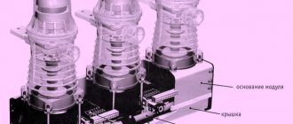
6 3.2. The switches perform the following operations and cycles: 1/ shutdown (O); 2/ switching on (B); 3/ switching on - switching off (BO), including without a deliberate time delay between operations (B) and (O); 4/ shutdown - turn on (OB) during any non-contact pause, 5/ shutdown - turn on - shutdown (OVO) with time intervals between operations according to paragraphs. 3 and 4; 6/ switching cycles: O 0, W s VO 180 s VO; O 0.3 s VO 20 s VO; O 180 s VO 180 s VO The number of shutdown operations allowed for each pole of the circuit breaker without inspection and repair of arc extinguishing devices (switching resistance resource) is: at a current equal to 100% of the rated shutdown current for circuit breakers VGT-UETM operations, for VGT-UETM -110 and VGT-UETM operations; at a current equal to 60% of the rated shutdown current for switches VGT-UETM operations, for VGT-UETM -110 and VGT-UETM operations; at operating currents equal to the rated current for switches VGT-UETM, and for VGT-UETM -110 and VGT-UE. The permissible number of switching operations for short circuit currents should be no more than 50% of the permissible number of switching operations; the permissible number of switching operations at load currents is equal to the permissible number of switching operations. The switches have the following indicators of reliability and durability: service life in terms of mechanical resistance before the first repair of the “switching on-random pause shutdown” cycles (B-tn-O); the service life before the first repair is at least 25 years, unless before this period the resources for mechanical or switching resistance have been exhausted; service life of at least 40 years. 4. DEVICE AND OPERATION 4.1. Switches of the VGT-UETM series belong to high-voltage electrical switching devices, in which the quenching and insulating medium is: for versions U1 and T1 SF6 gas, and for version HL1* a mixture of gases (SF 6 gas + CF 4 tetrafluoromethane) VGT-switches UETM -35 and VGT-UETM -110 consist of three poles (columns) mounted on a common frame and mechanically connected to each other. All three poles of the switch are controlled by one spring drive. In the VGT-UETM -220 switch, each pole has a frame and is controlled by its own drive. The operating principle of the switches is based on extinguishing the electric arc by the flow of SF6 gas (gas mixture), which is created due to the pressure drop provided by autogeneration, i.e. e. due to the thermal energy of the arc itself. The switches are switched on using the energy of the closing springs of the drive, and switched off by the energy of the spring of the switch's tripping device. 5. DEVICE AND OPERATION OF COMPONENTS 5.1. The frames of the VGT-UETM -35, VGT-UETM -110 switches and the poles of the VGT-UETM -220 switches are a welded structure on which a drive, a disconnecting device, columns and electrical contact pressure switches are installed. In the cavity of one of the support channels of the frame, closed with covers, there are series-connected rods connecting the drive lever with the levers of the poles (columns). One of the covers has viewing windows for the switch position indicator. The frame has eight holes with a diameter of 22 mm for fastening to foundation racks or supporting metal structures and is equipped with a special bolt for connecting a grounding bus. When specified in the order, support metal structures are supplied for a separate fee, having appropriate holes for fastening to the circuit breaker frame and two holes with a diameter of 36 mm for each support for fastening to foundation racks. The disconnecting device is installed on the end of the frame opposite from the drive and consists of disconnecting springs, compressed when the switch is turned on by a rod connected to the outer lever of the outer column. The springs are located in a cylindrical housing, on the outer flange of which there is a buffer device designed to dampen the kinetic energy of the moving parts and serving as a stop (travel limiter) when the switch is dynamically turned on. The pole of the VGT-UETM-35 and VGT-UETM-110 switch is a column filled SF6 (gas mixture) and consisting of a support insulator, an arc extinguishing device with current leads, a control mechanism with an insulating rod. The pole of the VGT-UETM -220 circuit breaker consists of two columns, the arc extinguishing devices of which are installed on the support insulators and are connected in series by two buses. To ensure uniform distribution of voltage across the arc extinguishing devices, shunt capacitors are connected to them in parallel. Each column is equipped with an individual density indicator. The arc extinguishing device contains openable main arc extinguishing contacts equipped with arc-resistant tips, a piston device for creating pressure in its internal cavity, and fluoroplastic nozzles in which the flow gas acquire the direction necessary for effective arc extinguishing. The high-pressure above-piston cavity and the sub-piston cavity are equipped with a valve system that allows for effective blowing in the arc combustion zone in all switching modes. In the upper part of the arc extinguishing device there is a container filled with an activated adsorbent that absorbs gas from the gas.
7 Loss moisture and gas decomposition products. In the on position, the main and arcing contacts are closed. When disconnecting, the main contacts first open with virtually no arcing effect when the arc extinguishing contacts are closed, and then the arc extinguishing contacts open. Sliding contact between the sleeve of the piston device and the movable contact pipe is carried out by contact elements placed in its recesses in the form of closed wire spirals. The column control mechanism is housed in a housing and a support insulator and consists of a splined shaft with an external lever and an internal lever. The splined shaft is mounted in bearings and is sealed by a “liquid seal” cuff system. The internal lever is connected to the movable contact rod through a non-adjustable insulating rod. An autonomous sealing valve is built into the body of the mechanism, through which a pressure alarm mounted on the frame of the switch is connected using a copper tube. The autonomous sealing valve consists of a housing and a spring-loaded valve, a connection unit for the alarm tube and a plug installed during transportation and after filling with gas when entering into work to ensure reliable sealing of the internal cavity of the column. The indicator tube is connected through two spring-loaded valves, while the indicator and tube can be removed for inspection and replacement. The indicating-type electric contact pressure indicator is equipped with a temperature compensation device that brings pressure readings to a temperature of 20 C with three pairs of contacts open at normal (working) pressure gas. The first pair of contacts closes when the pressure of the SF6 gas decreases to 0.44 MPa abs., and the gas mixture to 0.62 MPa abs., giving a signal about the need to replenish the pole. The second and third pairs of contacts close at a pressure of SF6 gas of 0.42 MPa abs., a gas mixture of 0.6 MPa abs., giving a signal about the need to turn on the blocking of the command to the control electromagnets or a signal for forced shutdown of the switch with a ban on its activation. Spring drive with motor factory of working (cylindrical screw) springs, is a separate unit placed in a sealed three-door cabinet. The drive has two shutdown electromagnets and is equipped with blocking devices that prevent: the passage of a command to the closing electromagnet: a) when the switch is on, b) when the springs are not charged, c) when the spring charging cam is in a position that prevents the switch from turning on, d) when the control mode switch is in the Local position ; e) after failure of the electric motor; transmission of a command to the tripping electromagnets: a) when the circuit breaker is open; b) when the control mode switch is in Local position; “idle” (with the switch on) dynamic discharge of the working springs; turning on the electric motor for winding springs when winding them manually; restart (“jumping”). The drive is equipped with alarm circuits: “Automatic power supply switch to the electric motor is not turned on”, “Malfunction in the system”, “Springs are not charged”, “2nd stage of heating is on”, “No power in the heating circuit”, “Contact position of the controlled switch” , “Local control of the power plant is enabled.” The drive provides for checking the serviceability of the heaters of the 1st and 2nd stages of heating the cabinet (when the SB2 (stop) button is pressed, the heaters are turned on due to the contacts ; connected in parallel to the thermostats SQ1 and SQ2). By special order: 1. The drive can be equipped with 2 current releases for currents of 5 A or 3 A, with a coil power consumption of 50 W; 2. Supply of a modular cabinet for the VGT-220 circuit breaker (see Fig. 13). The cabinet is designed to connect control and signaling circuits of switch pole drives in accordance with the circuit breaker pole control circuit for remote and local control, as well as circuits for blocking B and O operations when the gas density in the switch poles decreases. The drive allows you to slowly operate the switch contacts when setting it up without any additional (for example, jacking) devices. At the bottom of the cabinet (including the unit cabinet) there are plates with grooves of various diameters for installing cable entries. The diameter of the holes was selected taking into account the possibility of using imported cable glands. The drive is easy to maintain and reliable in operation. The circuit breaker frame and the drive cabinet have an anti-corrosion coating. The circuit breakers are transported in transport units: the circuit breaker frame with the drive installed on it, the tripping mechanism and elements of the mechanical connection of the poles; boxes with three columns: - for VGT-UETM -35 or VGT-UETM pcs; — for VGT-UETM pcs. Delivery of the frame in connection with the drive, tripping mechanism and elements of the mechanical connection of the columns ensures high factory readiness of the circuit breaker, simple and fast installation, practically requiring no adjustment. Columns are transported to the Customer filled with SF6 gas up to transport pressure (0.13-0.15 ) MPa abs. When installing the switches, the columns for the U1 version are filled with SF6 gas, and for the KHL1* version with SF6 SF6 gas and CF4 tetrafluoromethane to operating pressure without preliminary evacuation. The delivery set of the switches includes: a set of accessories (group spare parts set 1), necessary for carrying out gas technology work when commissioning the switch into operation and during its operation. Supplied for a group of switches shipped to one address; Gas cylinders and parts for connecting to them (group spare parts kit 2) are supplied in the quantity necessary to fill the switches in preparation for commissioning. Group sets of spare parts (1 and 2) are supplied for an additional fee if specified in the order. 7
8 6. OVERALL DIMENSIONS VGT-UETM series circuit breakers for 35 and 110 kv VGT-UETM series circuit breaker for 220 kV (double-break) (for unspecified dimensions, see above) Type of circuit breaker View E FGH (height of supporting metal structures) KLMNQ Weight of circuit breaker without supporting metal structures, kg (no more) VGT-UETM VGTZ-UETM -35 yes VGT-UETM depending on the order VGTZ-UETM -110 yes VGT-UETM VGTZ-UETM -220 yes Figure 1. Overall and installation dimensions of VGT-UETM series circuit breakers 8
9 Figure 1a. Overall and installation dimensions of switches of the VGT-UETM series (continued) 9
10 Figure 2. Overall, installation and connection dimensions of the modular cabinet for the VGT-UETM circuit breaker
11 Figure 3. Overall and connection dimensions of the installation of the VGT-UETM -110 circuit breaker (VGTZ-UETM -110) together with three TRG-UETM -110 current transformers on a factory two-support metal structure Figure 4. Overall and connection dimensions of the installation of the VGT-UETM -110 circuit breaker (VGTZ-UETM -110) together with six current transformers TRG-UETM -110 on a factory two-support metal structure 11
12 QUESTIONNAIRE SHEET - APPLICATION for the supply of SF6 circuit breakers of the VGT (VGTZ)-UETM series Manufacturer: Elmash LLC (UETM) Russia, Ekaterinburg, st. Front brigades, 22, tel. (343) , fax: (343) is filled out for each ordered circuit breaker or for a batch with a completely similar design of all circuit breakers in the batch Customer (city code) telephone Fax Name of the power facility, location of the circuit breaker installation Date of filling out the application 1. Number of circuit breakers ordered pcs. 2. Design according to the degree of air pollution (please note the ordered version) kV 3150A Dear Customer! kV 3150A kV 3150A 3. By track length (DPU) (mark the ordered version) 3.1. Standard design according to DPU external insulation with degree of pollution II* (specific DPU - 2.25 cm/sq.m.) 3.2. Special design of switches for 110 and 220 kV with degree of pollution III (specific DPU - 2.5 cm/sq) 3.3. Special design of switches for 110 and 220 kV with degree of pollution IV (specific DPU - 3.1 cm/sq) 4. According to climatic version Execution Operating temperature of the ambient air switch U1 from plus 40 C to minus 45 C HL1 * from plus 40 C to minus 55 C T1 From plus 55 C to minus 10 C 5. Version according to the height of the supporting structure Ordered version Version Switch Ordered version (check) Basic version with shortened factory supporting metal structures Version with high factory supporting metal structures Version without factory supporting metal structures VGT-UETM -110 VGT-UETM -220 VGTZ-UETM -110 VGTZ-UETM -220 VGT-UETM -35 VGTZ-UETM -35 VGT-UETM -110 VGT-UETM -220 VGTZ-UETM -110 VGTZ-UETM -220 VGT-UETM -35 VGTZ-UETM -35 VGT-UETM -110 VGT-UETM -220 VGTZ-UETM -110 VGTZ-UETM -220 VGT-UETM -35 VGTZ-UETM -35 H=678 mm H=678 mm H=988 mm H =988 mm H=678 mm H=988 mm Note: for the height of the supporting metal structure H, see Figure 1. H = 2200 mm H = at customer's request, specify height H = 2200 mm H = at customer's request, specify height H = 2200 mm H = at the customer's request, indicate the height H = 2200 mm H = at the customer's request, indicate the height H = 2200 mm H = at the customer's request, indicate the height H = 2200 mm H = at the customer's request, indicate the height You can download the electronic version of this application form on our website in the “Download Questionnaire” section and send it to us by email or fax (343) Drive version (mark the ordered version) Parameter name Required parameters for rated voltage Design for rated DC supply voltage = 220V or =110V control electromagnets Three-phase ~400V or ~230V Version according to rated alternating current Single-phase AC and ~230V voltage; =220V power supply to the electric motor of the Universal constant-window, including the motor current, springs of the constant drive =110V current 6.1. Additional options: Installation of two current distributors for 3A for current 5A (mark the ordered version) 7. Sets of supplied spare parts and accessories 7.1. Single set of spare parts - supplied with each circuit breaker at no additional cost 7.2. Group set of spare parts 1, containing accessories for gas technology work. Supplied (if specified in the order for an additional fee) for one or more switches shipped to one address Number of ordered sets 7.3. Group kit SPTA 2 containing gas cylinders (supplied when ordered at an additional cost) U1 HL* T1 Rated voltage Contents of the kit Consumption rates for one set rated voltage, kV number of switches to be filled pcs. Breaker design 35 kV kV 1 cylinder with SF6 gas kV 1 cylinder with SF6 gas and 1 110 kV cylinder with kV tetrafluoromethane kV 1 cylinder with kV SF6 Additional equipment (specify quantity) 8.1. Module cabinet for switches with a rated voltage of 220 kW. 1 cabinet for 1 switch 8.2. A set of consoles for joint installation with three TRG current transformers, a kit for 1 circuit breaker. A set of consoles for joint installation with six TRG current transformers, a set for 1 circuit breaker. Connecting busbars for joint installation with TRG current transformers, a kit for 1 circuit breaker. Design of a comprehensive diagnostic system for circuit breakers. Accounting for switching resource and or synchronous control of a circuit breaker. number of ordered sets. PC. 1) Attention! The use of KSDV must be provided for in the design for its installation. The supply of a device for an integrated circuit breaker diagnostic system (KSDV) is carried out for an additional fee. When ordering, you must fill out a separate KSDV order form. 9. Carrying out corporate supervision of installation and supervision of commissioning Required to maintain the Manufacturer’s warranty obligations Produced within the time period agreed with the Customer for a fee 10. Additional requirements of the Customer 11. Payment and shipping details: Consignee Station for wagons Payer Current account Bank Cor. account BIK INN OKONH OKPO Customer represented by M.P. (Signature stamp)
13 For notes: 13
14 For notes: 14
15 Switches of the VGT-UETM series at operating power facilities Substation Obninsk, Kaluga region Substation "Rostoshi", Orenburg Votkinskaya HPP, Perm Territory 15
16 620017, Ekaterinburg, st. Front brigades, 22 Sales department: tel.: (343) , fax: (343) Chief designer: tel.: (343) , fax: (343)
COLUMN SF6 GAS SWITCH VGT-110 KV
| Production of gas-insulated core switches with a rated voltage of 110 kV. for switching electrical circuits under normal and emergency modes in three-phase alternating current networks. | Buy |
Electroshield Samara began production of SF6 core switches with a rated voltage of 110 kV. The switches are designed for switching electrical circuits under normal and emergency modes in three-phase alternating current networks.
To place an order for VGT-110kV, you must send a request by email. mail
Contact tel. 89275578450
The switch has the following features:
- Steel elements are coated with hot zinc.
- Convenient gas density indicator with automatic compensation
- The switch position indicator is clearly visible visually.
- Reliable spring drive.
- Pressure relief system to protect the substation and personnel.
- Arc chute with integrated double contact technology and auto-blowing system.
- Maintaining the electrical strength of the circuit breaker insulation in case of
- Switching off capacitive currents without repeated breakdowns.
- Low noise level when switching on and off.
- Availability of two-stage heating and monitoring of its serviceability.
- Low level of overvoltages during switching
The switches comply with the requirements of GOST 52565-2006 Climatic design of the switches: U from minus 45˚С to plus 40˚С. HL* from minus 50˚С to plus 40˚С. Placement category 1 according to GOST 15150. Seismic resistance on the MSK-64 scale up to 9 points. Degree of insulation contamination III and IV according to GOST 9920-89. Reliability indicators: The lifespan of the circuit breaker in terms of mechanical resistance (M2) is 10,000 cycles. Resource for switching resistance - 20 shutdowns of rated short-circuit currents. Service life – 40 years. Warranty period – 5 years
See also:
www.electroshield.ds30.ru
COLUMN SF6 GAS SWITCH VGT-110 KV
Electroshield Samara began production of SF6 core switches with a rated voltage of 110 kV. The switches are designed for switching electrical circuits under normal and emergency modes in three-phase alternating current networks.
To place an order for VGT-110kV, you must send a request by email. mail
Contact tel. 89275578450
The switch has the following features:
- Steel elements are coated with hot zinc.
- Convenient gas density indicator with automatic compensation
- The switch position indicator is clearly visible visually.
- Reliable spring drive.
- Pressure relief system to protect the substation and personnel.
- Arc chute with integrated double contact technology and auto-blowing system.
- Maintaining the electrical strength of the circuit breaker insulation in case of
- Switching off capacitive currents without repeated breakdowns.
- Low noise level when switching on and off.
- Availability of two-stage heating and monitoring of its serviceability.
- Low level of overvoltages during switching
The switches comply with the requirements of GOST 52565-2006 Climatic design of the switches: U from minus 45˚С to plus 40˚С. HL* from minus 50˚С to plus 40˚С. Placement category 1 according to GOST 15150. Seismic resistance on the MSK-64 scale up to 9 points. Degree of insulation contamination III and IV according to GOST 9920-89. Reliability indicators: The lifespan of the circuit breaker in terms of mechanical resistance (M2) is 10,000 cycles. Resource for switching resistance - 20 shutdowns of rated short-circuit currents. Service life – 40 years. Warranty period – 5 years
www.ds30.ru
110 kV SF6 gas circuit breaker VGT and VGU 400a
Application area
Vacuum switches VRS-110 are used to complete open switchgears of 110 kV transformer substations and can be used to expand existing substations. They can replace the outdated one:
- air circuit breaker VVN 110,
- Tank low-oil switches VGP 110
- SF6 gas circuit breaker VGT 110 kV
- and others like that.
Design
The switch for voltage 110 kV has solid poles with silicone insulation. The poles use vacuum chambers specially designed for this circuit breaker. The spring drive provides the ability to manually turn on and off the circuit breaker. The drive control cabinet is located on the side of the switch body, which provides convenient and safe access to it.
Advantages of VRS 110 over SF6 circuit breakers:
- The stable state of the VRS-110 contact group is maintained throughout the entire service life, and the dielectric properties of SF6 gas decrease (due to the accumulation of decomposition products in the switching chamber as the number of switchings increases).
- The switching life of VRS-110 is 10,000 cycles, which is 2 times more than that of SF6 devices.
- VRS-110 does not require maintenance until after 10,000 switching cycles.
- Minimum installation time (6-8 hours) and minimum installation costs.
- VRS-110 are environmentally friendly and do not require additional disposal costs, like SF6 switches 110 40 2500.
- The reliability of the VRS-110 circuit breaker is higher than that of SF6 or air circuit breakers (the arc extinguishing part of the VRS-110 contains fewer moving parts).
- Possibility of operation in low temperature conditions (down to – 60° C) without additional heating.
Main technical parameters
| Options | Parameter value | |
| Rated voltage, kV | 110 | |
| Highest operating voltage, kV | 126 | |
| Rated current, A | 2 500 | 3 150 |
| Rated breaking current, kA | 31,5 | 40 |
| Thermal resistance current, kA (3 s) | 31,5 | 40 |
| Electrodynamic resistance current, kA | 81 | 102 |
| Total shutdown time, ms, no more | 47 | |
| Own turn-on time, ms, no more | 80 | |
| Own shutdown time, ms, no more | 32 | |
| Mechanical life, VO cycles | 10 000 | |
| Switching life at rated currents, VO cycles | 10 000 | |
| Switching life at rated shutdown currents, VO cycles | 25 | |
| Weight, kg | 1 645 | |
www.vsoyuz.com
Repair instructions for SF6 circuit breaker VGT-110 - Documentation
Contents of the material
DOCUMENTATION.
6.1. List of reporting documents.
6.1.1.
Based on the results of the work performed, the following types of reporting documents are drawn up: - act of completion of equipment repair work;
— list of equipment (appendix to the act);
— typical scope of repair;
— statement of completed work;
— a list of replaced units and parts during the repair of electrical equipment.
6.1.2. Repair documentation (statement of completed work, test report) for each piece of equipment is stored in the masters’ room at the outdoor switchgear.
6.1.3. The storage period for repair documentation is until the next major overhaul.
6.1.4. The person responsible for the safety of repair documentation is the foreman of the team for repairing outdoor switchgear and 6 kV switchgear equipment.
6.2. Forms of reporting documents.
— the act of completed equipment repair work is drawn up in the form of Appendix 1;
— typical scope of current repairs of the VGT-110 circuit breaker according to the form of Appendix 2;
— typical volume of average repair of the VGT-110 circuit breaker according to the form of Appendix 3;
— typical scope of overhaul of the VGT-110 circuit breaker according to the form of Appendix 4;
— statement of completed work TR of the VGT-110 circuit breaker in the form of Appendix 5;
— statement of work performed on the CP circuit breaker VGT-110 in the form of Appendix 6;
— statement of work performed on the CP circuit breaker VGT-110 in the form of Appendix 7;
— a list of replaced units and parts during the repair of electrical equipment is drawn up in the form of Appendix 10.
6.3. Drawing (sketch) of a general view.
Figure 1. General view of the VGT-110 circuit breaker
6.4. Repair checklist.
6.4.1. In accordance with clause 2 of Appendix 7 POKAS(rem) Book No. 1 No. 00-18-01POKAS(rem) the development of control charts is not required if there are approved standard statements of scope of work, which are annex to the technical specifications.
Chief Engineer
ACT OF EXECUTED WORKS
The commission appointed by order No. _______ dated _______________, consisting of:
Commission members: _____________________________________________________
Based on the submitted documents (reporting repair and technological documentation) and the results of acceptance tests, it accepted the equipment from repair and established an assessment of the quality of the repaired equipment (the list of equipment is in the appendix to the report).
The warranty period for repaired equipment is ______month.
Equipment with other warranty periods: _______________________________________________________________________
The quality of repair work performed is assessed by ________
Application:
List of equipment accepted for repair on ____ sheets.
Note
: The report is drawn up for a group of equipment that is part of one installation (system)
Chairman ________________________________________________________________
Commission members
:_______________________________________________
Column switches VGT UETM-110 kV
The switches are designed for switching electrical circuits in normal and emergency modes, as well as operating in automatic reclosure cycles in three-phase alternating current networks with a frequency of 50 Hz and a rated voltage of 110 kV.
Rated voltage 110 kV, highest operating voltage 126 kV, rated current 3150 A, rated breaking current 40 kA
Column switch block
It is a prefabricated free-standing block of a supporting metal structure, intended for outdoor installation in electrical installations of three-phase alternating current of industrial frequency 50 Hz, as part of open switchgears (OSD) of voltage class 110 kV, in areas with temperate and cold climates, in normal and polluted atmosphere conditions . Assembly and installation of the block is carried out directly at the construction site.
- 1. Column switches voltage class 110 kV
The unit is equipped with high-voltage circuit breakers of 110 kV voltage class. Products from different manufacturers present in both the Russian and foreign markets can be used as optional equipment. The developed blocks can be used both in the new construction of substations and in the reconstruction of facilities.
At the customer’s request, the support block can be manufactured in accordance with the manufacturer’s own choice of high-voltage circuit breakers for the voltage class 110 kV with a short period of adjustment of the design parameters, while maintaining the connecting dimensions to the construction part (foundations) of the substation (PS).
- 110, 220 kV blocks are structurally made up of support posts fastened together by crosspieces or jibs and beams installed on them for equipment, usually of the same type.
- Metal structures are made from steels St3 and 09G2S, depending on climatic conditions, as well as seismic activity of the outdoor switchgear construction site.
- All blocks are designed with bolted connections, and are also supplied in the form of enlarged assembly units, which eliminates on-site welding when installing blocks, and also speeds up assembly.
- The presence of markings on each product in the form of a glued aluminum marking plate with the product drawing number in a visible place makes assembly convenient and eliminates the depersonalization of elements.
- The ability to install secondary switching cabinets, hanging cable trays, which reduces the cost of manufacturing separate support frames and additional racks, as well as additional foundations for them.
- After manufacturing in production, the unit undergoes control assembly in the workshop with the preparation of an acceptance test report. This eliminates the risk of the block not being assembled at the construction site.