Disconnecting loaded electrical circuits always carries the risk of sparking. Load shedding on high-voltage lines is especially dangerous. A powerful electric arc formed when switching unprotected contact blades can lead to the destruction of power contacts and failure of electrical devices. A load switch equipped with devices for emergency arc extinguishing is capable of protecting the circuit switching process.
Load switches (LCBs) belong to those types of switching devices that, in terms of the level of permissible currents, occupy an intermediate position between conventional disconnectors and special rated current switches capable of cutting off overcurrents in emergency situations. Despite the fact that switching the rated current with a load switch is allowed, the device is not designed to switch off overload currents in the event of a short circuit. For these purposes, the use of special high-voltage fuses is provided.
Application
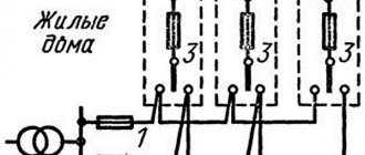
Load switches are used in distribution networks for the purpose of switching lines and power transformers operating at rated voltages. The devices can be used to switch on/off auxiliary loads, but are not intended to provide short-circuit protection unless fused designs are installed (see Figure 1).
Rice. 1. HV with fuses
High-voltage lines of 6 - 10 kV are equipped with such power disconnectors, for currents not exceeding 400 - 600 A. Relay devices are used to switch and protect more powerful power lines. In low-power networks, it is allowed to use HVs without fuses.
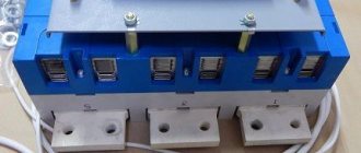
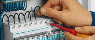
There are compact switches for loads up to 100 A, which are easily mounted in switchgears. Such switches are similar in appearance to the design of a circuit breaker (see Fig. 2) and are installed at the inputs of networks of apartment and private buildings. They are controlled only manually and do not turn off when the protection current reaches.
Rice. 2. Low power load switches
The presence of a modular power switch does not eliminate the need to protect wiring in emergency modes by other means. In particular, emergency shutdown of the home electrical network is provided by automatic batch switches, but it is not recommended to use them for frequent load shedding due to rapid wear of the contacts. In this sense, the load switch is more reliable, since its contacts are designed for such operating modes.
Autogas type load switch VNP-M1-10/630-20.
Load switch type VNP-M1-10/630-20
Load switches of type VNP-M1-10/630-20 are produced by the Nalchik High-Voltage Equipment Plant (Nalchik, Russia). Having undergone modernization, switching off the load has become safe to use. Intended for operation in cabinets of complete switchgear (KRU), in complete transformer substations (KTS), as well as in cells of stationary one-way and two-way service chambers (KSO) with a voltage of 10 kV three-phase alternating current with a frequency of 50 and 60 Hz for networks with grounded or isolated neutral. The switch is equipped with a built-in hand-wound spring drive, which is designed for both local and remote control.
Source: forca.ru
37563
Bookmarks
Comment 1
Latest publications
Igor Makovsky and Alexey Smirnov discussed issues of reliability of energy supply in the Kursk region
Yesterday, at 16:24 37
Igor Makovsky: uninterrupted power supply to consumers is our contribution to achieving national goals
March 3 at 21:51 36
In 2022, Kurskenergo energy workers installed more than 15,000 anti-magnetic seals
March 3 at 11:30 44
National Research University "MPEI" signed a cooperation agreement with the Rosatom Technical Academy
March 1 at 15:07 47
Rosseti Siberia informs residents of the Novokuznetsk region about changes in the power grid maintenance scheme
March 1 at 08:05 62
Igor Makovsky: power engineers provide comprehensive support to people in need of help
February 28 at 20:46 52
How to expand the market for regional medical equipment manufacturers?
February 28 at 19:33 47
Reliable power supply for electrical substation equipment in Vladimir is guaranteed
February 28 at 17:58 64
Choosing the type of heating for a cottage village: central boiler room
February 28 at 15:16 54
The Kalugaenergo branch provided socially significant facilities in the Kozelsky district with street lighting
February 25 at 12:08 108
Comments 1
Advantages and disadvantages
The switching devices under consideration have strengths and weaknesses.
Benefits include:
- lower cost compared to other types of switches;
- fast and reliable switching on and off of rated load currents;
- the possibility of using cheap fuses for overload protection;
- The presence of a visible break in the contacts of high-voltage HVs, which makes it possible to do without an additional disconnector.
Flaws:
- limited service life;
- breaking the circuit is possible only for currents within the rated power values;
- Once the fuse has tripped, it must be replaced.
Tests and inspections, what devices are used to control
The operation of high-voltage circuit breakers requires the following checks:
- visual inspection for external defects;
- measuring the resistance of the insulating coating;
- checking the resistance of windings and contacts, when comparing the obtained value with standardized indicators;
- response time;
- contact temperatures and others.
Instrumental measurements are performed with a megger, thermometer and stopwatch. Also, to test devices, special stands designed to perform these types of work can be used.
Design and principle of operation
The design of a high-voltage load switch is very similar to the design of three-pole disconnectors. On the frame there are movable knives rotating in a vertical plane and having a sickle shape. They enter the chamber where the fixed contacts are located.
The rotation of the knives is controlled using mechanisms, manual drives, or semi-automatic devices. An electromagnetic drive using a solenoid provides remote load disconnection of high-voltage devices, and in some cases, operation in automatic control.
Figure 3 shows a drawing of a three-pole HV with a manual drive.
Rice. 3. Drawing of VNA load switch
Please note (drawing on the left) that the design provides for the installation of fuses that are not shown in the drawing. All live parts are separated from the frame by powerful insulators (picture on the right).
To ensure the required speed of contact separation, spring mechanisms are used. When the shaft turns, the spring accumulates potential energy, which at a certain moment is released, directing the accumulated power to the movement of the knives. The spring mechanism is clearly visible in Figure 4.
Rice. 4. VNA load switch with spring mechanism
The load switch kit may include stationary grounding blades. These additional protection elements have mechanisms to block erroneous actions by personnel.
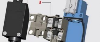
The main difference between HVs and disconnectors is the presence of arc extinguishing devices that ensure the safety of fixed and moving contacts during switching. Extinguishing the electric arc, which inevitably ignites when the loaded circuit is turned off or on, occurs in arc-extinguishing chambers equipped with liners made of polymers. The arcs are extinguished by the flow of evaporation products of the liners, formed under the influence of high temperatures of the resulting discharge.
Depending on the design of the HV, the extinguishing principle may differ. It should be remembered that extinguishing chambers do not ensure the absolute absence of an arc, which, although for a very short period of time, still occurs. The task is to suppress the growth of the discharge as quickly as possible by eliminating the conditions for its existence.
The damping effect is achieved in various ways: by blowing ionized air from the contacts, filling the chambers with special mixtures of gases, or creating a vacuum. Depending on the principle of arc suppression, different types of switches are distinguished.
Load switches type VNR. Design features and principle of operation.
In addition to load switches of the VN type, load switches of the VNR-10/400-10z type are also widely used in the CIS countries.
Design of load switch type VNR-10/400-10z
Six support insulators 2 are installed on the welded frame 1, while the contacts 3 with the holders of the main knives 4 are fixed on the lower insulators, and the main 6 and arc-extinguishing contacts, which are closed by arc-extinguishing devices, are fixed on the upper insulators. Using lever 8 and insulating rod 7, movement is transmitted from the switch shaft to the knives. To ensure the required shutdown speed, special springs 13 and shock-absorbing rubber washers 14 are mounted on the circuit breaker. Stationary grounding knives 10 are connected to the circuit breaker frame by flexible connections 9 and are driven by the shaft 11 of the grounding device.
To turn on the load switch, the handle of the drive lever is moved from bottom to top, while shaft 15 rotates and, using insulating rods, turns on the contact knives. To disconnect the switch, the handle of the drive lever is moved from top to bottom or remotely from the button with making contacts, while the shaft rotates under the action of the trip springs and turns off the switch.
Load switch type VNR-10/400-10z a) general view of the load switch; b) section of the arc chute; c, d) circuit breaker layout 1 - arc-extinguishing chamber: 2, 9 - fixed and movable working contacts; 3, 5 — levers of the load switch shaft and grounding knives; 4 - spring; 6 — shaft of grounding knives; 7 — grounding knives; 8 - flexible connection; 10, 12 - fixed and movable arc extinguishing contacts; 11 — organic glass insert; 13, 17 — drive rods of the load switch and grounding knives; 14, 16 — drives of the load switch and grounding knives: 15 — PKT fuses; 18 — half frame; 19 — frame
Kinds
According to the method of extinguishing the arc in the chambers, HVs are divided into the following types:
- autogas;
- SF6;
- vacuum;
- air;
- oil;
- electromagnetic.
Autogas (gas generating) switch
The device is intended for operational switching of power electrical equipment. Arc suppression occurs under the influence of gases generated in the extinguishing chamber. An insert made of urea-formaldehyde resin or polymethyl methacrylate, located inside the chamber, heats up at lightning speed at the moment the arc extinguishing contacts are switched. Under the influence of high temperature, the top layer of polymer evaporates, and the resulting flow of gases intensively extinguishes the electric arc.
The condition for evaporation of the liner is created by arcing contacts, starting the process of “longitudinal blowing”. In the on state, the rated current flows through the main contacts.
Autogas HVs are actively used in Russia and the CIS countries. They are used at substations and installed in switchgears of 6-10 kV power networks with an insulated neutral. Basically, they are installed where it is not economically profitable to use installations of another type, and the use of disconnectors is prohibited by the rules of the Electrical Installation Regulations.
This type of switches has the lowest cost and high maintainability. These advantages are contributing to the growing popularity of gas-generating circuit breakers.
Vacuum high voltage circuit breaker
A very effective, but expensive device that allows you to turn off not only rated load currents, but also overcurrents during a short circuit. The contacts of vacuum switches are located in a vacuum chamber with ultra-low pressure (about 10-6 - 10-8 N/m). The absence of gas creates a very high resistance, which prevents the arc from burning.
When the contacts are opened/closed, an arc still occurs (due to the formation of plasma from the metal vapors of the contacts), but it goes out almost instantly at the moment of crossing zero. Within 7 - 10 μ/s, vapors condense on the surface of the contacts and on other parts of the camera.
There are varieties:
- vacuum circuit breakers up to 35,000 V;
- devices for voltages exceeding 35 kV;
- vacuum contactors for networks of 1000 V and above.
Main advantages:
- switch operation in any position;
- switching wear resistance;
- stable work;
- Fire safety.
The disadvantages include the relatively high cost due to the complexity of the camera production technology.
Gas-insulated HVs
In switching devices of this type, SF6 gas is used to extinguish the arc. The device operates on the principle of autogas switches, but instead of air, sulfur hexafluoride (SF6) with the addition of other gases is used to extinguish the arc.
SF6 gas enters the extinguishing chamber body from a hermetic container, which is not released into the atmosphere, but is reused. There are core and tank devices (see Fig. 5).
Rice. 5. Tank SF6 HV
The designs of such switches use built-in current transformers. Modern SF6 HVs can operate in ultra-high voltage switchgear, reaching 1150 kV.
SF6 circuit breakers
Figure 1 – Design of a gas-insulated circuit breaker
An SF6 circuit breaker operates by isolating the phases between each other using gas (usually SF6 electric flow gas is used - the so-called “SF6 gas”). When a signal is received to turn off the equipment, the camera contacts open. They create an electric arc, which is placed in a gas environment. The arc separates the gas into individual components, and the high pressure in the reservoir helps to extinguish it.
Advantages:
- Multifunctional (can be used at any voltage)
- High response speed
- Possibility of use in critical situations (fire, earthquake)
- Long service life
Flaws:
- High cost of construction Inability to work at low temperatures
- Difficulty of maintenance
- The need to install a special foundation for such a structure
Symbol and marking
To mark load switches, alphanumeric symbols are used, grouped into groups:
VN X-X-00/0-0 xx 0 X0.
Note that the given structure of the designation may differ in the markings of different types of structures.
Let's consider one of the options.
- The first group of letters contains information about the type of switch. VN – load switch. Sometimes the letter H is missing, but in its place, and most often an X in the second position indicates the type of product or design option.
Letter designation of construction types:
- M – oil;
- MM – low oil
- A – autogas.
(SF6 gas switches have their own designation structure).
Letter designation of execution options:
- M – modernized;
- P – spring drive;
- P – manual drive;
- E – electromagnetic.
An X in the third position can indicate the location of the drive:
- P – right;
- L – left.
In the fourth position (00) there are numbers indicating the rated voltage in kV.
5th position (/0) – rated shutdown current, in kA.
6th position (0) – rated (through) current of the switch.
7th position (xx) – location of grounding knives (sometimes climate version). p – behind the fuses, c – on the side of the grounding contacts.
8th position (0) – indicates the type of device sending the command to shutdown (if available).
9th position (X0) – climatic version and placement category.
Example: marking VVE - 15 - 25/ 680 - UZ means: Vacuum switch, with an electromagnetic drive, designed for voltage 15 kV, thermal current - 25 kA, rated current VN - 680 A, used in temperate climates, intended for indoor installations.
Figure 6 shows an example of the designation on the diagram.
Rice. 6. Designation on diagrams
Price list for load switches
Retail prices as of 01/01/2021 (prices changed from 03/01/2021 due to rising copper prices) . Discounts are available for orders of more than 3 units. The price of the switch includes a manual drive and a set of hardware for fastening the busbar.
| Name | Price including VAT, rub. |
| VNA-P(L)-10/630-20 UHL2, without grounding blades | 18 145 |
| VNA-P(L)-10/630-I(II)-20z UHL2, grounding blades on one side | 20 865 |
| VNA-P(L)-10/630-III-20z UHL2, grounding blades on both sides | 23 790 |
| VNA-P(L)-10/630-I(II)-20zp UHL2, grounding blades on one side, with fuse contacts | 25 310 |
| VNA-P(L)-10/630-III-20зп УХЛ2, grounding blades on both sides, with fuse contacts | 28 080 |
| VNR-10/(400)630 UHL2, without grounding blades | 18 740 |
| VNRz-10/(400)630-I(II) UHL2, grounding blades on one side | 21 380 |
| VNRz-10/(400)630-III UHL2, grounding blades on both sides | 24 350 |
| VNRP-10/(400)630 UHL2, without grounding blades | |
| VNRPz-10/(400)630-I(II) UHL2, grounding blades on one side, with fuse contacts | 24 550 |
| VNRPz-10/(400)630-III UHL2, grounding blades on both sides, with fuse contacts | 26 595 |
| VNVR-L(P)-10/630-I(II)-20z UHL2, grounding blades on one side | 51 180 |
| VNVR-L(P)-10/630-III-20z UHL2, grounding blades on both sides | 53 885 |
| VNVR-L(P)-10/630-I(II)-20pz UHL2, grounding blades on one side, with fuse contacts | 55 010 |
| VNVR-L(P)-10/1000-I(II)-20pz UHL2, grounding blades on one side, with fuse contacts | 69 695 |
Technical specifications
Load switches are characterized by three important parameters:
- rated voltage;
- thermal current;
- rated current HV.
Other parameters are taken into account based on location conditions, the desired switching method and the choice of type of execution.
As an example, we provide a table of parameters for VN:
| Product type | U nom, kV | Fuse type | I no. fuse, kA | maximum current, kA | Weight (without drive), kg |
| VNP-3 | 3 | PK-Z | 80 | 31,5 | 50 |
| 200 | 31,5 | 55 | |||
| VN-16 | 6 | — | — | — | 36 |
| 10 | — | — | — | 36 | |
| VNP-16 | 6 | PK-6 | 50 | 20 | 62 |
| 80 | 20 | 64 | |||
| 160 | 20 | 78 | |||
| VNP-16 | 10 | PK-10 | 32 | 12,5 | 52 |
| 50 | 12,5 | 65 | |||
| 100 | 12,5 | 79 | |||
| VNP-17 | 6 | PK-6 | 50 | 20 | 62 |
| 80 | 20 | 64 | |||
| 160 | 20 | 78 | |||
| VNP-17 | 10 | PK-10 | 32 | 12,5 | 52 |
| 50 | 12,5 | 65 | |||
| 80 | 12,5 | 79 |
Technical parameters of other types of load switches can be obtained from the seller or from other sources of information.
Connection
On power lines, HVs are placed in front of power transformers. If the technical documentation provides for the presence of disconnectors, they are installed after the HV.
In a multi-apartment electrical network, HVs are installed in distribution panels (if there is access) or in another accessible place, separately for each apartment.
In production workshops, it is advisable to install a mini switch near each machine to ensure the possibility of emergency shutdown.
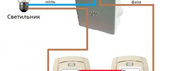
In a household electrical network, load switches are usually installed in front of the meter, although they can also be installed after the meter. But always in front of protective devices - automatic machines, plugs, etc. As an example, we give a diagram for connecting a high-voltage voltage in a single-phase network.
Rice. 7. HV connection diagram in a home network
Breaker Maintenance
Switches should be inspected regularly to determine if there is any damage, which can be determined by the appearance of the device. When equipment is stopped as part of maintenance, it must be cleaned, adjusted, carbon deposits removed from contacts, and other necessary operations provided for in the manufacturer’s technical documentation.
Every 4 years, devices undergo regulated maintenance, and every 8 years - major repairs. The need for routine repairs may be due to:
- violation of the integrity of elements;
- noise and crackling when the switch operates;
- overheating of contacts;
- increased oil consumption.
The work is usually carried out at the place of operation of the devices, and trained personnel as part of a specialized organization are involved in their implementation.
High-voltage switches are important devices, the serviceability of which determines the correct performance of switching operations.
You can read more in the textbook (starting from page 237, and about choosing a switch from page 268): Open and read the book