Hello! A vacuum circuit breaker is a switching device used for switching alternating electric current with a frequency of 50 Hz rated value in high voltage power circuits, as well as for protecting equipment from short circuits.
The share of use of this type of switches in high-voltage networks is about 60% of all switching devices with voltages up to 35 kV. Use in 110 kV lines is just beginning to gain momentum. The operating equipment has not yet exhausted its service life and is being replaced gradually. What justifies the demand for this type of switching devices? Let's figure it out: find out the principle of operation, design features of the “vacuum generator”, touch on the advantages, disadvantages and characteristics.
Purpose
“Vacuum units” are used in switchgear cells (complete switchgears) and for switching asynchronous motors. The most appropriate use is in networks of 6, 10, 35 kV. The devices are suitable for open switchgears with a voltage of 110 kV, complete transformer substations, modernization of existing lines, as an alternative to outdated air and oil devices.
The vacuum switch performs the same functions as its counterparts. The device provides:
1. Guaranteed switching of equipment by personnel in manual and automatic mode.
2. Shutdown in the event of an emergency in a short time.
3. Reliable passage of electrical loads.
The only difference is in the method of extinguishing the arc that occurs when the power contacts break at the moment of operation. In the “air vent” the discharge is literally blown away by a powerful air flow, in oil ones a dielectric environment is created. And here the vacuum comes into play.
Design Features
Each modification of the low-voltage and high-voltage vacuum circuit breaker differs in its layout. This is due to operation at different current and voltage ratings. Manufacturers also do not stand aside. Everyone implements their innovative ideas in hardware, which affects the completeness of the device with additional elements and layout. We won’t understand it, but look at the design of the device as a whole and figure out how it works and works.
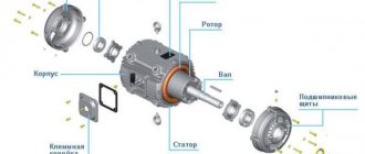
The switch consists of a common housing with a switching drive, on which 3 poles of power circuits are fixed. Inside each there is a sealed vacuum chamber, consisting of a contact group and special screens that protect the internal insulating surfaces from metal deposits due to contact erosion.
The contact system includes 2 elements: a fixed contact, rigidly attached to the lower flange, and a movable contact, connected to the upper flange so that the tightness of the vacuum arc-extinguishing chamber is not broken.
The principle of operation of the switch is reduced to opening the moving contacts of three poles simultaneously using a spring drive mechanism manually or automatically. Control occurs using standard relay circuits or through electronic switching units. These elements can be installed directly on the switch body or made in a remote version in the form of a special panel (remote panel) or cabinet.
How to choose a vacuum circuit breaker?
The device is selected taking into account its nominal parameters, which are considered in relation to the parameters of the existing network at the installation site. The choice is made according to the criterion of the maximum loaded operating modes expected for operating conditions.
The rated voltage of the vacuum circuit breaker is allowed to be equal to (or increased) in relation to the rated voltage of the system powered through the circuit breaker.
The rated long-term current parameter is selected higher than the rated current of the supplied system. The rated cutoff current parameter is selected higher than the maximum value of the calculated short-circuit current (the moment of contact divergence is taken into account).
The technical specification plate is the first thing you pay attention to when choosing a switch. Based on the parameter values, you can already determine whether the device is suitable for a specific installation or not
From the point of view of possible short circuit conditions, the choice is made taking into account the most severe conditions.
The aperiodic component value is calculated taking into account the short circuit conditions with zero voltage in any of the phase lines. In this case, the aperiodic current parameter set by the equipment manufacturer should be taken into account.
Arc extinguishing method
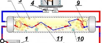
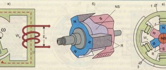
The operation of the switch is based on certain physical processes, regardless of the voltage rating of the device. Let's look at the detailed operating diagram.
Both contacts operate in a vacuum environment, achieved by removing gases from the arc chute. Thanks to this, high dielectric strength is achieved. When the device is switched off by the drive, a vacuum gap is formed between the contacts. When the surfaces open, metal vapor appears, through which the electric load current continues to flow. Under the influence of high voltage, metal ions move in one direction and are heated to the state of plasma.
The switch operates on alternating current, which changes its direction according to a sinusoidal law. When its value is zero, the arc fades out, and metal ions are no longer released and settle on the contact surfaces or electrostatic screens of the arc chamber. At the same time, a vacuum is formed in the gap between the contacts, which prevents the further flow of load current and an arc discharge cannot occur in the next half-cycle of the sinusoid.
Thanks to this operating principle, good performance is ensured, and contact destruction during discharge is minimal.
Inclusion
In the open position of the switch, the contacts of the vacuum chamber (VDC) are held in the open state by the action of the trip spring, which is transmitted to the movable contact of the VDC by means of a traction insulator. To turn on the module, the winding of the electromagnetic drive is discharged into a pre-charged switching capacitor of the control unit. A current pulse flowing through the winding of an electromagnetic drive as a result of the discharge of a capacitor creates a magnetic field in the gap between the armature and the flat magnetic core. As the current in the winding of the electromagnetic drive increases, the force of electromagnetic attraction between the armature and the flat magnetic core increases to a value greater than the holding force created by the trip spring. At this moment, the drive armature begins to move towards the magnetic core, pushing the traction insulator and the movable contact of the VDC. As the armature moves towards the magnetic core, the air gap decreases, due to which the force of attraction of the armature increases. The rapidly growing electromagnetic force rapidly accelerates the moving parts of the module to a speed of approximately 1 m/s. This speed is optimal for the switching process and allows you to avoid contact chatter when they collide, while significantly reducing the likelihood of a breakdown of the vacuum gap before the contacts are closed. The accelerating armature generates a counter-EMF in the turns of the electromagnetic drive winding, which prevents a further increase in the current in the winding and even slightly reduces it. At the moment the contacts close, the movable contact stops, and the armature continues its movement another 2 millimeters, pressing the contacts through the additional contact prestressing spring. Having reached the flat magnetic core, the armature stops, being magnetized to the drive magnetic core. At the moment the armature stops, it stops inducing back-EMF, which leads to an increase in the current required to saturate the ring permanent magnet until it achieves the necessary magnetic properties. A ring magnet magnetized to saturation creates a powerful residual magnetic flux sufficient to keep the drive armature (and, accordingly, the module contacts) in the on position even after the switching current is turned off by the auxiliary contact. Mechanical resistance tests have shown that the holding force generated by the permanent magnet is sufficient to keep the module in the on position for as long as required by operating conditions, even when exposed to vibration and shock loads. The actuator tripping spring also compresses as the armature moves, accumulating potential energy to perform the module tripping operation. The movement of the armature is transmitted to the synchronizing shaft, rotating it at an angle of 44° during movement, to provide indication of the module status, control of auxiliary contacts and actuate the locking mechanisms of the switchgear.
Advantages
Vacuum circuit breakers exhibit all their positive qualities in electrical installations where a large number of switchings occur. Therefore, the devices work especially effectively in control systems of transformers and electric motors.
We highlight the following advantages:
• High reliability compared to oil or air circuit breakers. What does it mean? The failure rate of vacuum circuit breakers is significantly lower than that of the above-mentioned switching devices. This can confidently be called the main advantage.
• Long service life. The switch can last 25 years, after which it is replaced with a new one.
• Performance. The reason for this is that vacuum is more susceptible to electrical breakdown than oil or air. Therefore, the stroke of the contacts of the arc-extinguishing chamber at the circuit breaker is only 6-10 mm, versus 100 mm for oil models. The response speed is about 2 ms, that is, very fast. In addition, the vacuum design has a long mechanical life.
• Low operating costs. This is due to the arcing environment. In the same air or oil switches there is a need to replenish it. Vacuum doesn't need anything like that. The poles are manufactured in a sealed and non-dismountable design.
• Relative simplicity of design. There are no additional elements in the form of oil tanks or compressor units that require constant monitoring and maintenance.
• The switch performs its functions equally effectively regardless of orientation in space.
• High switching resistance. The circuit breaker without inspection and repair is capable of withstanding up to 20 thousand outages with operating current values and up to 200 outages with short-circuit current (the resource depends on the specific modification of the device and the value of the short-circuit current). No type of switches is capable of providing such an operating period without preventive measures.
• Ease of repair and maintenance. The entire structure is built according to the block principle. One is replaced by another without the need for disassembly and restoration.
• Small dimensions. At the same operating values of currents and voltages, the dimensions and weight of the vacuum circuit breaker will be significantly less than its analogues.
• Safety. The absence of oil or gas leaks determines the high degree of fire and environmental safety of the switching device. The vacuum switch operates more quietly than the air vent. The latter “hits” very loudly, like the shot of a gun, which can be heard 500 m away.
Switch selection
The selection of switches is carried out by trained people. In the event of an error, there is a risk of emergency situations and accidents. When choosing, you must be guided by the following criteria:
- rated operating voltage;
- characteristics of the control system, its understandability for operating personnel;
- maximum short-circuit current and rated operating characteristics;
- device switching speed;
- required frequency of preventive maintenance;
- climatic and operational characteristics.
Important! The choice of a vacuum switch must be approached with special responsibility. Errors can lead to device failure at the most inopportune moment.
As a result, there is a risk of unplanned consumer outages.
Flaws
If everything is very clear with the advantages of the design, then with the disadvantages it is a little more complicated. They are insignificant. But they deserve some attention.
• Higher cost compared to analogues. Yes, a vacuum device is more expensive, but operating costs are lower.
• Possibility of depressurization of the vacuum chamber due to its damage. This happens very, very rarely; manufacturers pay due attention to product quality.
• When switching small currents, overvoltages are possible. Therefore, in conjunction with the “vacuum manifold”, appropriate protection for the equipment must be installed.
Operation and Maintenance
Low-maintenance vacuum circuit breakers are recommended to be checked at least once every 4 years. But the frequency may be different. Everything depends on the design of the switching device and is regulated in the technical documentation.
Servicing vacuum circuit breakers involves checking the insulators for cracks, chips, contamination and traces of discharges.
The pole chamber is sealed, the vacuum is maintained throughout the service life of the device. Therefore, the poles are not repaired, but replaced entirely.
In addition, various electrical tests are carried out:
• Insulation resistance measurement.
• High voltage test.
• Inspection of mechanical parts.
• Measurement of response time.
• Inspection of the condition of contacts (the method is based on measuring DC resistance).
After all the tests carried out, a regulatory document is drawn up indicating the operability of the device or its unsuitability for further operation.
Inclusion
In the open position of the switch, the contacts of the vacuum chamber (VDC) are held in the open state by the action of the trip spring, which is transmitted to the movable contact of the VDC by means of a traction insulator. To turn on the module, the winding of the electromagnetic drive is discharged into a pre-charged switching capacitor of the control unit. A current pulse flowing through the winding of an electromagnetic drive as a result of the discharge of a capacitor creates a magnetic field in the gap between the armature and the flat magnetic core.
As the current in the winding of the electromagnetic drive increases, the force of electromagnetic attraction between the armature and the flat magnetic core increases to a value greater than the holding force created by the trip spring. At this moment, the drive armature begins to move towards the magnetic core, pushing the traction insulator and the movable contact of the VDC.
As the armature moves towards the magnetic core, the air gap decreases, due to which the force of attraction of the armature increases. The rapidly growing electromagnetic force rapidly accelerates the moving parts of the module to a speed of approximately 1 m/s. This speed is optimal for the switching process and allows you to avoid contact chatter when they collide, while significantly reducing the likelihood of a breakdown of the vacuum gap before the contacts are closed.
The accelerating armature generates a counter-EMF in the turns of the electromagnetic drive winding, which prevents a further increase in the current in the winding and even slightly reduces it.
At the moment the contacts close, the movable contact stops, and the armature continues its movement another 2 millimeters, pressing the contacts through the additional contact prestressing spring.
Having reached the flat magnetic core, the armature stops, being magnetized to the drive magnetic core. At the moment the armature stops, it stops inducing back-EMF, which leads to an increase in the current required to saturate the ring permanent magnet until it achieves the necessary magnetic properties.
A ring magnet magnetized to saturation creates a powerful residual magnetic flux sufficient to keep the drive armature (and, accordingly, the module contacts) in the on position even after the switching current is turned off by the auxiliary contact.
Mechanical resistance tests have shown that the holding force generated by the permanent magnet is sufficient to keep the module in the on position for as long as required by operating conditions, even when exposed to vibration and shock loads. The actuator tripping spring also compresses as the armature moves, accumulating potential energy to perform the module tripping operation.
The movement of the armature is transmitted to the synchronizing shaft, rotating it at an angle of 44° during movement, to provide indication of the module status, control of auxiliary contacts and actuate the locking mechanisms of the switchgear.
About the manufacturers
Today, vacuum circuit breakers are produced by many companies, among which the most notable are: General Electric, Siemens, ABB, the Tavrida Electric group and other well-known brands.
Experts believe that vacuum switches are a promising type of switching devices. Due to their advantages and high performance parameters, these devices are most suitable for use. Designs are constantly being improved and characteristics are improved. Thus, in 2007, prototypes appeared, designed for operation in networks with a voltage of 220 kV. But manufacturers do not stop at the achieved result; development is underway to create vacuum arc extinguishing chambers designed for 750 kV.
Historical reference
Appearance of a vacuum circuit breaker
Vacuum circuit breakers were first mentioned in the early 30s of the 20th century, when the devices were used to disconnect relatively low-current circuits operating at voltages up to 40 kV. To obtain reliable vacuum dampers capable of switching off significant currents in circuits at high potentials, a whole series of studies was required. During their implementation, approximately by 1957, the processes observed during high-voltage arc combustion were fully studied and systematized. It took another two long decades to move from prototypes produced in single copies to mass production of modern devices.