The main feature of a sound switch is that they respond to sound. For example, the simplest option is for cotton. That is, a person only needs to reproduce a sound command in order to control the light in a room or even in the entire apartment. A sound switch, or so-called clap switch, is practical and can always pleasantly surprise your guests.
A cotton switch for almost any radio amateur will be difficult to make independently, since it really has a rather intricate design. To decide whether to install such a high-tech switching device in your own apartment or not, you should first understand what kind of switch it is, what types and features it has.
Application
The light switch claps on and off in response to the noise it makes. The operating algorithm is as follows: the first clap is switching on, the second is switching off.
It is recommended to install devices of this type only in quiet rooms. Premises of this type include bedrooms, storage rooms, utility rooms, and basements. It is irrational to install cotton devices in rooms where there are many people (offices, living rooms, industrial areas), since extraneous noise leads to false reactions of the devices.
The most common place to install a slam light switch is in the bedroom. It is very convenient to control the lighting without getting out of bed. Cotton systems are popular in families with small children, since to turn the light on or off you no longer need to reach for a high-mounted switch.
Many people confuse cotton and acoustic devices. The acoustic switch is triggered by any noise, and the clap switch is triggered only by claps.
Types of sound switches
Acoustic switches can respond to voice commands and claps
The following types of acoustic switches exist:
- Devices that react to cotton. It is programmed in advance at what number of claps a particular command will be executed.
- Devices that respond to voice or a preset command.
- Combined devices (for example, light-acoustic switch). They can be equipped with sound, light or motion sensors. These are the most technologically advanced devices in which the risk of false alarms is minimized.
- Devices for low-current systems. Used to connect a video camera or transmit a command to security.
Acoustic switches have become popular due to their ease of use. They are useful for the elderly, bedridden patients and young children. Devices of this class are already actively used in the Smart Home system.
Clap switch with microcontroller
A microcontroller is a small piece of silicon covered in plastic and has metal terminals that does not perform any functions without software. Its use in any appliance makes it smart and involves use in the Smart Home system.
Difference from standard sound switch:
- reduced response time to 100 microseconds;
- possibility of reprogramming, setting individual parameters;
- increased range;
- the ability to change the signal threshold value (to eliminate interference and avoid responding to false commands);
- smooth change in lighting brightness;
- fewer components;
- short circuit protection.
Dimmer acoustic switch
Optical-acoustic switch for hidden wiring
Dimming is the regulation of the load that the device consumes. Using dimmers, you can smoothly turn on the light, adjust the brightness of an LED lamp or incandescent light bulb. Not suitable for fluorescent lamps. Dimmer devices can also be used to regulate the temperature in irons, soldering irons, kettles and other household appliances.
An optical-acoustic switch is needed for dimmer switching on electricity. The operating principle of the microcircuit is as follows:
- the signal in the form of sound reaches the microphone;
- sound is converted into impulse;
- the pulse is sent to the microcontroller and passes through the amplifier, charging the capacitor;
- a large charge is achieved, after which the comparator switches;
- the zero at the output changes to a pulse;
- the transit generator is activated, which sends impulses;
- the triac opens, through which power passes to the lamp;
- the capacitor loses voltage level;
- a signal with increasing phase retardation is supplied to the triac;
- The light turns on smoothly.
If you select all component values correctly, the lamp turns off with a pause of up to 3 minutes. To operate the dimmer, you need a lamp with a power of at least 40 W. The voltage on the optical-acoustic switch varies smoothly in the range from 0 to 220 V.
Advantages:
- Thanks to smooth switching on, the lamp service life increases;
- the ability to create lighting of the required brightness in a certain place;
- the ability to control light using intelligent systems.
Disadvantages include the inability to open the network in the event of a short circuit and the lack of a protective function against overloads.
Dimmers are not recommended for radios, televisions and products with switching power supply, as they cause interference.
Types of switches for home (domestic use)
The various types of switches used in everyday life must be convenient, safe, and have an attractive design. They differ from each other in types and types. Depending on the installation method, the switch can be built-in or installed externally. Nowadays, a rotary key is most often used as controls; such switches are common in Europe.
Types of switches for the home
In the USA they prefer to use lever-type switches (toggle switches), apparently not wanting to break away from tradition. But this is now, but in the old days, when Thomas Edison just made his invention, rotary switches were used. They were known throughout the world in the first half of the 20th century and switched up to several circuits in 3–4 positions (batch switch). Package switches are still used in many old utility panels.
To turn on the lamp, use a single-key switch; for chandeliers, use a two-key or even three-key switch. For rooms such as the toilet and bathroom, use a double light switch. Let us add that in our age of advanced technology, many switches with additional functions have appeared. These are the functions:
- Illuminated switch for night time
- switch with shutdown timer.
- Switches with brightness control.
If everything is clear with the first type of function, then the second is used to save light in small rooms (closets, bathrooms) where people enter for a short time and forget to turn off the lights. And the third can be used together with those lamps that support the dimmer function (dimmer). Sometimes they are included in the kit, since this type of device has not yet been standardized.
Unusual types of switches
A light switch with a motion sensor is another way to save electricity and is very convenient. The light turns on if the infrared sensor detects human movement within the sensor's field of view. Repeated motion may turn off the lights, or a timer may do so after motion has been detected. A switch with a motion sensor does not require any action from a person; his presence is sufficient.
There is one so-called smart switch, this is a clap switch. The way it reacts to noise, it can turn on involuntarily. Inside it there is a microphone, which is also an amplifier and a microprocessor device in order to recognize the nature of the sound. It may not work the first time, as it stores the sound from the user in memory for later comparison.
And there are such things
The floor switch is made in the form of a button with a locking mechanism. It can be turned on by pressing your foot with little force, and is designed in such a way that the weight of your foot will not damage it.
The ceiling switch is also a button with a lock, to which the force is transmitted from a lever with a cord attached to it. The mechanics are hidden behind a decorative cover. To turn it on or off, you need to lightly pull the cord.
Principle of operation
The device operates using a microcontroller installed in it. The controller authorizes turning the light on and off by clapping. If desired, this device can be used to control other electrical household devices (air conditioners, fans, etc.).
A typical audible light switch contains an electronic microphone with a preamplifier. This component amplifies the sound entering the device, which allows you to record even the quietest pops. The operation of the amplifier is controlled using transistors VT1 and VT2. The circuit is controlled by a pair of resistors R2, and diodes VD1 and VD2 are used to equalize the signal.
The sound from the clap passes through the microphone, where the electrical impulse is amplified and transformed. Next, the sound is equalized due to the work of rectifying diodes. The sound is controlled by a resistor (if the sound volume level is below the specified level, the resistor will prevent the device from operating). When the signal on the capacitor is leveled, the voltage increases and the transistor switch VT3 opens.
The light turns off and on after sequential charging and discharging of the capacitors. At the end of a full cycle of activity (one more bang), the resistor and capacitor C10 are discharged in four seconds. This causes the device to turn off.
Connection rules and specifics
Although limit switches themselves are designed quite simply, they are used in equipment with complex electrical circuits. Consequently, their connection must be carried out by specialists and strictly according to the schematic diagrams, based on the technical features.
Let's look at an example of connecting a simple mechanical switch in a 3D printer. This is necessary in order to set the extreme coordinates for its carriage. The plug-in limit switch has 3 contacts - COM, NO, NC. When the sensor is open, the first and last contacts are at +5V. The second contact (NO) is grounded.
In the diagram, contacts COM (1) and NO (2) are in a closed state, and COM and NC (3) are open. When the printer carriage reaches its extreme position, the COM and NC contacts are connected and it rebounds by 2 mm
The sensor is connected using two wires - red and black. When the device fires, you should hear a typical click. The indicator switch is connected in the same way, but it also has a third wire - green.
Its activation is indicated by a lit LED and a click. Its connectors on the board have designations: for the red wire V (+5 V), for black - G (ground), for green - S (signal).
The same letters indicate the connectors on the optical switch. It will more accurately control the operation of the carriage, but may malfunction in dusty conditions and sunlight. The activation of the optical pair is accompanied by the inclusion of a light-emitting diode and occurs completely silently.
Limit switches are widely used by furniture makers, installing them in wardrobes. Connection is carried out according to the instructions included with each model. The diagram shows the location of the fastening of the plastic structure with the key. For the middle door, it must be installed so that it does not interfere with the correct movement of the other section door along the guides.
The diagrams show the procedure for connecting limit switches for sliding doors in sliding wardrobes (option b) and for swing doors (option a)
If a limit switch is installed for a swing door, it is fixed using self-tapping screws inside the cabinet. When the door is closed, the button presses, opens the circuit and the lighting does not work. When open, the door releases the button and the lighting turns on.
How it works
The simplest cotton switch has an electronic microphone in its circuit; in addition, an amplifier is installed with it in the form of two transistors connected to each other. These small details amplify any sound entering the microphone several times. Thanks to this, the switch can be activated even with a slight clap.
The amplified sound pulse is supplied to a powerful transistor, a relay coil is connected to its collector, the power circuit of which is connected to the lighting network. That is, the transistor controls this relay, and it, in turn, closes or opens the contacts in the lamp power circuit.
A capacitor is installed in the microphone circuit. You can select its capacity and thereby adjust the sensitivity of the microphone to the supplied sound.
simple acoustic switch circuit
The acoustic switch is designed on the same principle. The scheme works as follows. The sound captured by the microphone is converted into an electrical signal (voltage). The amplification cascade amplifies the voltage, in this form it is supplied to a powerful transistor, and from it to the relay coil. Current begins to flow through the relay, the magnetic core is retracted, thereby closing the power contacts of the relay in the lighting circuit. The light comes on.
Particularly experienced and competent electricians and radio amateurs will be able to assemble such a circuit on their own.
Specifications
As an example, let’s look at the characteristics of a standard device for turning the light on and off by clapping.
Device data:
- Power is supplied from a standard network with a voltage of 220 Volts.
- The maximum total power of consumers does not exceed 300 Watts.
- Sound control ranges from 30 to 150 decibels.
- Permissible temperature range: from 20 degrees below zero to 40 degrees above zero.
- Housing protection class - IP30.
A variety of lamps are used in the network:
- Incandescent and halogen light sources.
- Energy-saving or fluorescent light bulbs.
- LED devices.
The specified characteristics comply with the requirements of the law of the Russian Federation number 261. This act regulates the rules for the rational use of electrical energy.
The equipment is similar in size to a matchbox, that is, compact. This makes it possible to install it close to the lamps. The device is fixed using self-tapping screws or double-sided tape.
Acoustic switch circuit
There are a huge variety of acoustic switch (AS) circuits: on transistors, logic chips, flip-flops, etc., but we will assemble our device on a microcontroller. Using a microcontroller, you can quite simply implement algorithms of varying complexity with minimal circuit modification or no modification at all.
The first and integral element of any acoustic switch is a microphone. The microphone converts the audio frequency signal into alternating voltage. The simplest electret microphone will suit us.
One terminal of the microphone is connected to the negative, and the second, through a trimming resistor R1, with a resistance of 510 kOhm, to the positive. Using R1, you adjust the microphone sensitivity. Next, the alternating signal from the microphone output through a 1 µF capacitor C1 is fed to an amplifier made on a single BC547 transistor. The emitter of the transistor is connected to the minus, and the collector is connected to the plus through resistor R2, with a resistance of 1 kOhm. The amplifier is adjusted using a tuning resistor R3 with a resistance of 1 MOhm.
Next, the amplified signal is fed to the input of the ATmega8 microcontroller. Depending on the number of received pulses, which corresponds to the number of claps, the microcontroller outputs a high or low potential to the corresponding pins. In this circuit, we use three pins of the MK microcontroller, which operate as output. They feed three similar circuits. Let's consider the operation of one circuit.
When there is a high potential (+5 V) at the MK output, transistor VT2 of the 2N2222 series, connected to the MK by resistor R4 (1 kOhm), opens and relay coil K1 receives power. When relay K1 is triggered, its contacts close in the lamp power circuit and thus it lights up.
The relay coil K1 should be shunted with a reverse diode VD1 to protect against overvoltage, since the coil has some inductance, and if the circuit breaks, a voltage surge may occur, although not significant in this case, but it is better to be safe. Almost any diode with a current of at least 100 mA will do; you can use 1N4148.
Any relay can be used, but you should focus on the following parameters: supply voltage 5 V, voltage of the closing contacts - alternating, 230 V. The contact current is determined by the load of the circuit that the contacts will close and open. I used the following type of relay: HW32-005VDC-A. If you find a relay with a coil supply current of no more than 20 mA, then you can do without a transistor switch.
The acoustic switch circuit is powered from a stabilized power source with a voltage of 5 V. You can take any ready-made power supply or assemble it yourself, as described in this article.
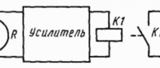
Voice relay
I offer a simple acoustic machine for switching on various actuators. The essence of the circuit (Fig. 1) is as follows. At a certain level of acoustic noise near the highly sensitive sensor-microphone VM1, the threshold level of which is set by trimming resistor R1, the signal amplified by the operational amplifier DA1 is supplied to the transistor switch VT1-VT2, which supplies power to relay K1. The relay with its contacts (they are not shown in the diagram) closes the load power supply circuit. After the noise stops, the load is turned off.
Fig.1. Schematic diagram of an acoustic machine
This method is used in microdictaphones, which automatically switch to recording mode when there is a sound signal. I use this circuit to automatically turn on the ultrasonic intercom.
This circuit will serve well in a lighting machine. Then it should be supplemented with a final stage with a turn-off delay of 3...4 minutes. If you install such a machine, for example, in the hallway, the light will light up automatically when there is the slightest noise (a door opening or a voice) and go out after a few minutes in complete silence.
In the initial state, both inputs of the DA1 microcircuit are in a state of equilibrium, and a very weak signal, on the order of several millivolts, is received at the base of the transistor VT1, which is insufficient to open the transistor. When sound is applied to the microphone, alternating voltage is supplied to input 2 of the op-amp. The multiply amplified signal from pin 6 of the op-amp, further amplified by transistor VT1, goes to the electronic switch on transistor VT2, which, in turn, switches the actuator - relay K1.
The relay switch-off delay when the sound influence on the microphone disappears depends on the values of C5 and R2. If the delay is not needed, these elements are excluded from the circuit. When a longer turn-off delay is needed, the C5 rating should be increased. With the ratings indicated in the diagram, the turn-off delay when powering the circuit at 12 V will be 1 min ±10%. If the capacitance of capacitor C5 is increased to 2000 μF, the turn-off delay at the same supply voltage will increase to 10 minutes. However, in the latter case, the accuracy of the exposure time is lost and the dependence on the duration of the initial impact of sound vibrations on the microphone increases.
Diode VD1 is used to eliminate bounce of relay K1 contacts. K1 is a low-power relay of type RES10, RES15 for an operating voltage of 9...11 V. To switch powerful load circuits with a high supply voltage, it is necessary to observe safety measures and use a relay with the appropriate permissible current through the contacts. The VM1 microphone is a DEMSh capsule or similar with a winding resistance of 200...250 Ohms and higher. Good results are obtained when using an FEM electret capsule of various modifications as a microphone (previously used as a built-in microphone in cassette tape recorders).
To eliminate interference and other interference, the microphone must be connected to the device with a short shielded cable no more than 20 cm long. When rigidly attaching the device body to other structures (for example, to a vertical wall), you should wrap the microphone capsule with foam rubber and not screw it to the device body, so that interference when various shocks (for example, the slamming of a neighboring door) did not affect the microphone.
As VT2, you can use medium-power silicon transistors KT603, KT630 or their analogues with any letter indices. KT361 with any letter index is suitable as VT1.
A device that is correctly assembled from serviceable parts requires virtually no setup. You only need to use trimming resistor R1 to select the operating threshold of the device.
Another electrical diagram
There are many options on the Internet of varying complexity depending on the configuration, but not all of them are functional. Defects appear during manufacturing. The presented electrical circuit has been tested in practice.
Here VD1 is intended to protect transistor VT3. To use a relay, a diode must be installed . If you decide to install a light load, we recommend replacing the diode with a jumper.
Connection diagram and installation
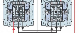
Below is a diagram of a clap light switch. Based on it, you can connect this device.
The white conductors available on the device are connected to the network. The load is connected to the black wires. To connect copper conductors, you will need terminals. The black conductors are connected to the lamp bulb. These devices are connected in parallel.
The switch is powered via a single-key switch. If you need to turn it off, you just need to press the switch.
The sound sensitivity is controlled by the corresponding regulator. It is recommended to use the average audio value.
Installation, connection and configuration
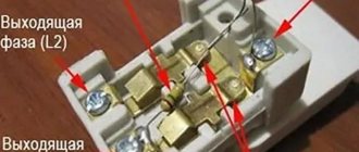
Connecting the relay to the lighting circuit is extremely simple:
- serial connection;
- We connect the power line wiring to terminals L, N, and the polarity at the input does not matter. It is not necessary, but it is desirable that the phase becomes on L and zero on N, but as already said, this is not important, and if you mix it up, the relay will work fully;
- We connect the wires going to the light bulb to the output terminals.
The contact points can be hidden under the cover, the wires can be clamped with an external terminal block. The sensor is fixed with bolts, screws, or double-sided tape. Although this is not desirable, the device can simply hang on the wires, with a minimum stable position and reliable fixation of the wires with clamps, since it is lightweight. The user must determine with what noise level the location should be selected according to the configured settings, so that there are no false activations.
The position should be such that the light does not interfere with work, if there is a sensor that monitors the daylight hours.
Settings
The built-in microphone is highly sensitive and if not adjusted, the risk of false activations will be significant. For configuration, a standard sound sensor with an adjustment option has selectors (buttons, wheels). One is for setting the noise limit limits at which operation occurs. It is believed that the optimal level is 50 dB (equivalent to clapping your palms). Others set a time period after which a shutdown occurs after recording sound waves.
If the device, for example, is located far from the doors, then the sensitivity is increased, if there is a lot of background noise, it is decreased.
How to connect?
The cotton switch “Ekosvet-X-300-L” in question consists of a block in which the entire circuit is mounted, and two pairs of wires - white and black. The white ones need to be connected to a 220 V electrical network, the black wires are connected to the lighting load.
The lamp receives zero (directly) and phase (through an ordinary household switch) from the distribution box. These two wires are connected to the white wires. You can do this using the old-fashioned twisting method, but it is better to use special self-clamping terminals.
The black wires are connected to the lamp socket itself. That is, with the usual circuit, phase and zero from the supply network would go directly to the lamp socket, and so you also additionally inserted a cotton (or acoustic) light switch into this circuit.
The block itself must be secured to the body of the lighting fixture. The unit has a sensitivity regulator, with which you can set the desired level of cotton. It is most advisable to set the so-called medium level, so that it is not too light, otherwise the switch will start to operate at the slightest tap, and not too strong, so as not to knock off your palms.
The clapper switch is powered through a regular keypad mounted on the wall. If you need to remove a fancy sound device from the circuit, it will be enough to turn off the key switch.
All that remains is to experimentally test the results of your work. When operating correctly, Ecosvet-X-300-L will only respond to clapping of palms. Tap with a hammer, bring a running vacuum cleaner close to the lamp, beat it in a mug with a spoon, turn on a hammer drill, tease with a mobile phone signal. We don’t know what your experiments will show, but there have been cases when cotton switches were triggered by the sound of a working hammer drill or the ringing sound of a metal spoon hitting a mug. This is further confirmation that there are few ideal things in the world; any device, especially in electrical engineering, has, along with advantages, a number of disadvantages (even if completely insignificant).
Where is the switch installed?
A cotton or acoustic switch created using a microcircuit is best installed on the walls - where the standard model was usually located. A do-it-yourself option will most likely have very low sensitivity, unless, of course, you undertake to implement complex circuits.
A voice switch purchased at a special store can be installed anywhere - even on the ceiling. Just before this, you need to familiarize yourself with its technical characteristics, and, again, pay special attention to sensitivity. In this case, the rule most often applies is that the more expensive and technologically advanced the model, the greater its functionality.
It is important to consider that a voice or clap switch purchased on a Chinese website for two pennies is unlikely to work properly. So, in order to save on this purchase, it is better to make it yourself using the necessary parts. So, if all these characteristics and nuances completely suit a person, then he can easily afford to install a cotton or voice switch in his apartment. These models are easy to use, do not require frequent replacement and, moreover, add manufacturability and uniqueness to any room, since they are rare.
Slam switch testing
Before connecting it, you need to configure the device for the presence of extraneous sounds. After this, you need to configure the device to trigger from extraneous sounds:
- From a hammer.
- The phone rings.
- Perforator work.
- Clattering of dishes.
After this, it is necessary to provoke false alarms of the device. After conducting all the experiments, you need to draw conclusions. If your device does not respond to extraneous sounds, then it works fine.
Installation nuances
The device is installed on a one- or two-key switch. The mains voltage must be 220 V.
You will need to arrange a break in the electrical circuit going to the key switch, and install an acoustic-type device at this point. And install the monitoring sensor in the chandelier body.
After installing and connecting the switch, a series of tests must be carried out to check the quality of the work done. To do this, you need to simulate household noises, carefully monitoring the reaction of the installed device.
The following noises are considered to be inherent in the house:
- noise from household appliances;
- the sound of dishes;
- the sound of a hammer;
- telephone trill, etc.
Create similar sounds in turn and see if the system works on them. Responses you don't want can be removed by adjusting the microphone sensitivity.
To create an acoustic-type switch with your own hands, you must have skills in working with radio-electronic and electrical parts. However, anyone with electrical installation experience can install such a device.
Manufacturers
The most famous models presented on the Russian market are “Ecosvet” and “Claps”. Let's look at their main characteristics.
Switch "Сlaps"
One of the newest developments is the “Claps” cotton switch model. In this device, the sound is processed using a microprocessor; it does not react to any extraneous noise, but is tuned to several claps in a row (this is the most important operating condition).
It is permissible to install several such switches in one room, each of them will react to a certain number of claps, and accordingly turn on the light, humidifier, fan, TV or stereo system. This switch model is suitable for any household appliances that have an electrical cord.
Perhaps to some, the clap switch may seem like a toy or a completely unnecessary device. Others, on the contrary, are passionate about the idea of creating their own “smart home” so that lights and electrical appliances turn on and start working on command or clap. Arrange your life the way you want, but at the same time make it as comfortable as possible.
Ecolight switch
The Ecosvet device is designed to work with 220 Volt light bulbs.
Main parameters of the device:
- load - 300 Watt;
- sound signal spread - from 30 to 150 decibels;
- housing protection level - IP30;
- permissible temperature range - from 20 degrees below zero to 40 degrees above zero;
- cost - from 350 rubles.
“Ekosvet” is fixed with self-tapping screws using the mounting legs. It is not recommended to install the device in noisy rooms. Despite the fact that “Ekosvet” is configured to clap, false alarms are possible.
The figure above shows the device connection diagram. "Ecolight" is connected to a conventional switch to provide the ability to de-energize the circuit and stop its operation.
How to choose
Before purchasing, you need to decide in advance for what purpose the acoustic switch is being purchased. Devices for home use, for the garage, entrance or street are different, since each environment has its own level of external noise. An incorrect choice will result in the device either not working or responding to any sound.
Cotton switches can be installed on 4 devices. For example, one clap will be responsible for turning on the light, two for the fan, and so on. Claps must be done in a row.
For chandeliers with a large number of lamps, you can buy a switch with several buttons. Such devices have several channels and can be connected to a specific group of light sources.
A sound switch is a convenient device for turning lights or household appliances on and off. They can respond to voice commands, claps and other specified sounds. Such devices are used in the Smart Home system; they can also be installed in an ordinary apartment.
Advantages and disadvantages
The most important advantage of a sound switch over classic ones is its simplicity and ease of use. The user does not need to think about where to install the switch.
Main advantages:
- work with any electrical appliances or light sources;
- the ability to turn on and off a household appliance or light from anywhere in the room;
- no extra wires;
- reliability and long service life;
- noiselessness;
- safety.
Flaws:
- Modern sensors can recognize the sound that is needed to turn it on and off. The user needs to know exactly what signal the sensor will respond to.
- The sensitivity area is limited. In a large room you will have to clap loudly or move closer to the sensor. If you increase the sensitivity, the sensor may falsely respond to similar sounds.
For radio amateurs who want to make a clap switch with their own hands, the disadvantage is the complexity of the electronic circuit.
Criterias of choice
Before you acquire such a device, you need to determine for what purposes it is needed. On the staircase, in the courtyard and entrance, you can install the most common acoustic sensor that responds to any noise from the surrounding area. This option will allow a person climbing stairs or crossing a darkened area to reach their destination without fear of a blackout. If you install a relay that turns off after a certain period of time, an elderly or slow-walking person will find himself in the dark. The shutdown delay can be adjusted if it is provided by the manufacturer, or design changes can be made to an already purchased device.
There are other requirements for devices of a certain type:
- the street sensor must be reliably strengthened and equipped with protection from natural influences (this is especially important in regions with problematic climates;
- if the purpose of the purchase is to save lighting, it is better to purchase a model equipped with a photo relay
- the principle of operation of a dimmer acoustic switch is useful in a personal plot, in a country house - the lighting will turn off as soon as the external space no longer needs additional light, but it is also useful where people leave the room for a short time and return again (in the kitchen, in the production workshop ;
- the range of action is important if you plan to control a large space; for apartment conditions, the minimum indicators are sufficient.
Sometimes in reviews of such products you can find insistent assurances about the need to purchase sensors from a branded manufacturer with a proven reputation and high cost. At home, you can perfectly use homemade sensors that you assemble yourself. If you have no knowledge on this issue, you can simply buy a reliable domestic device.