Regulatory documents for laying
The wiring of electrical cables through walls must be carried out in compliance with the requirements of two regulatory documents:
- Rules for the construction of electrical installations (PUE) are one of the main sets of laws in the electric power industry. This book is “sacred” for electricians. She explains in as much detail as possible what equipment is installed where and how correctly.
- SNiP 3.05.06-85 (in clause 3.18) (building codes and regulations) - considers the principles that should be taken into account when constructing buildings and laying electrical communications and cables in them.
Rules for electrical installations
In addition, installation rules can be found in the Federal Law of June 22, 2008 - “Technical Regulations on Fire Safety Requirements.” Article 82 of this document describes the standards.
Any major electrical work, especially when installing cables in a new building, is carried out in accordance with plans, drawings and various design documentation. Without compliance with this requirement, the building will not be accepted for operation.
Cable penetrations through walls: rules and regulations
We often have to solve the problem of laying cables through the external walls of buildings and internal partitions of rooms.
There are many requirements for laying cable lines through fire partitions. In the process of selecting materials and installing cable systems, it is very important to comply with each of them; this affects not only the convenience of replacing cable lines, but also the safe use. Cable laying through walls and ceilings must be carried out strictly in accordance with the requirements of regulatory documents.
Basic requirements for laying cable lines. The main two regulatory documents regulate the requirements for this type of work.
The first document is the PUE, which should always be referred to when it comes to the installation of electrical installations.
PUE 2.1.58
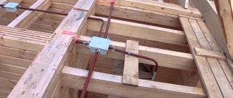
In places where wires and cables pass through walls, interfloor ceilings or where they exit outside, it is necessary to ensure the possibility of changing electrical wiring. To do this, the passage must be made in a pipe, box, opening, etc.
In order to prevent the penetration and accumulation of water and the spread of fire in places of passage through walls, ceilings or exits to the outside, gaps between wires, cables and pipes (ducts, openings, etc.), as well as backup pipes (ducts, openings, etc.) should be sealed. . p.) easily removable mass of fireproof material. The seal must allow replacement, additional installation of new wires and cables and ensure the fire resistance limit of the opening is not less than the fire resistance limit of the wall (floor).
The second document is SNiP 3.05.06-85, which describes the standards for the construction and installation of electrical devices.
SNiP 3.05.06-85 P 3.18. Passages of unarmored cables, protected and unprotected wires through fireproof walls (partitions) and interfloor ceilings must be made in sections of pipes, or in boxes, or openings, and through combustible ones - in sections of steel pipes.
Openings in walls and ceilings must have a frame that prevents their destruction during operation. In places where wires and cables pass through walls, ceilings or where they exit outside, the gaps between the wires, cables and the pipe (duct, opening) should be sealed with an easily removable mass of non-combustible material.
The seal should be made on each side of the pipe (duct, etc.). When laying non-metallic pipes openly, sealing the places where they pass through fire barriers must be done with non-combustible materials immediately after laying cables or wires into the pipes.
Sealing the gaps between pipes (ducts, openings) and the building structure (see clause 2.25), as well as between wires and cables laid in pipes (ducts, openings), with an easily removable mass of fireproof material should provide fire resistance corresponding to the fire resistance of the building structure .
In general, cable penetrations through walls must meet the following requirements:
• cable penetration must provide the ability to replace wires and cables during operation. • when installing cable penetrations, it must be ensured that fire, smoke and moisture cannot spread through the installation openings from one room to another.
Source
Basic principles of electrical cable installation
PUEs are written in complex technical language. If we simplify the points that tell us how to pass a cable through walls, we can highlight the following basic rules:
- Electrical wiring must be replaceable. This requirement is described in paragraph 2.1.58 (talking about the 7th edition). The ability to replace cables is necessary to repair or modernize existing electrical networks. For example, if during the construction of a residential building, grounding was not taken into account in the design, but now it is necessary to replace the old cable with a new one, which contains separate PE and N conductors.
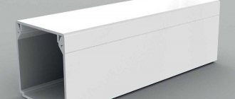
- Cables must be protected from environmental influences and mechanical damage. This is done using various non-flammable trays, cable ducts, electrical skirting boards, metal or plastic corrugated tubes. Such protection saves the cable from moisture and dirt from the outside and prevents it from burning.
- The holes through which the cable passes through the walls are sealed (covered) with moisture-resistant, non-flammable materials. This plug should be easy to remove when replacing wiring.
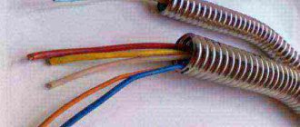
Running cable through the wall
Cables in the wall of a residential building
To install the wire in the wall, you will need to drill a hole. It’s easier to do this with a hammer drill switched to drilling mode. The main thing is not to damage the cables already in the wall with the drill. Ideally, a hidden wiring detector is used to detect them. Prices for this device start at about 1000 rubles. It is not advisable to purchase it for drilling one hole. To find cables, you can try cheaper methods:
- Logical. No equipment needed. It is important to understand that the wires in the wall run near the outlets and switches. Usually from the side or from above, less often - diagonally.
- Using an indicator screwdriver. What you need is a transistor one, into which 3 button batteries are inserted. It costs a penny and is sold in any store from the “thousand little things”, “everything for the home” series, etc. An indicator screwdriver can feel the cable in the wall at a depth of 10-15 mm. Application requires practice.
- Some radio-based devices are capable of sensing electromagnetic fields from wires carrying current. These include radios, hearing aids or walkie-talkies. The method is dubious, but sometimes it works.
Device for detecting wiring in the wall
Installation tools
For drilling you will need at least a hammer drill with a drill. If the hole in the wall has a large diameter, then a hammer with a pick or chisel will also come in handy. The cable penetrations themselves through the walls are easiest to make in a metal or PVC pipe. During work, dust from concrete and plaster is generated. It should be removed with a special construction vacuum cleaner, because a simple household vacuum cleaner will not last long in this mode of operation.
Once the wire is installed, you will need a putty knife to seal any remaining voids. A tool for cutting pipes, measuring and applying markings to the wall will also be useful.
Hammer with drill for drilling holes
Open electrical wiring indoors / PUE 7
2.1.52. Open laying of unprotected insulated wires directly on bases, on rollers, insulators, on cables and trays should be carried out: 
1. For voltages above 42 V in rooms without increased danger and for voltages up to 42 V in any rooms - at a height of at least 2 m from the floor or service area. 
2. For voltages above 42 V in high-risk and especially dangerous areas - at a height of at least 2.5 m from the floor or service area. 
These requirements do not apply to descents to switches, sockets, starting devices, panels, lamps installed on the wall. 
In industrial premises, descents of unprotected wires to switches, sockets, devices, panels, etc. must be protected from mechanical influences to a height of at least 1.5 m from the floor or service area. 
In domestic premises of industrial enterprises, in residential and public buildings, the specified slopes may not be protected from mechanical influences. 
In rooms accessible only to specially trained personnel, the height of openly laid unprotected insulated wires is not standardized. 
2.1.53. In crane spans, unprotected insulated wires should be laid at a height of at least 2.5 m from the level of the crane trolley platform (if the platform is located above the crane bridge deck) or from the crane bridge deck (if the deck is located above the trolley platform). If this is not possible, then protective devices must be installed to protect personnel on the trolley and crane bridge from accidentally touching the wires. A protective device must be installed along the entire length of the wires or on the crane bridge itself within the location of the wires. 
2.1.54. The height of open laying of protected insulated wires, cables, as well as wires and cables in pipes, boxes with a degree of protection not lower than IP20, in flexible metal hoses from the level of the floor or service area is not standardized. 
2.1.55. If unprotected insulated wires intersect with unprotected or protected insulated wires with a distance between the wires of less than 10 mm, then additional insulation must be applied to each unprotected wire at the intersection points. 
2.1.56. When crossing unprotected and protected wires and cables with pipelines, the clear distance between them must be at least 50 mm, and with pipelines containing flammable or flammable liquids and gases - at least 100 mm. When the distance from wires and cables to pipelines is less than 250 mm, wires and cables must be additionally protected from mechanical damage for a length of at least 250 mm in each direction from the pipeline. 
When crossing hot pipelines, wires and cables must be protected from high temperatures or must be designed accordingly. 
2.1.57. When laying parallel, the distance from wires and cables to pipelines must be at least 100 mm, and to pipelines with flammable or flammable liquids and gases - at least 400 mm. 
Wires and cables laid parallel to hot pipelines must be protected from high temperatures or must be designed accordingly. 
2.1.58. In places where wires and cables pass through walls, interfloor ceilings or where they exit outside, it is necessary to ensure the possibility of changing electrical wiring. To do this, the passage must be made in a pipe, duct, opening, etc. In order to prevent the penetration and accumulation of water and the spread of fire in places of passage through walls, ceilings or exits to the outside, the gaps between wires, cables and the pipe (duct, opening) should be sealed etc.), as well as backup pipes (ducts, openings, etc.) with an easily removable mass from non-combustible material. The seal must allow replacement, additional installation of new wires and cables and ensure the fire resistance limit of the opening is not less than the fire resistance limit of the wall (floor). 
2.1.59. When laying unprotected wires on insulating supports, the wires must be additionally insulated (for example, with an insulating pipe) in places where they pass through walls or ceilings. When these wires pass from one dry or wet room to another dry or wet room, all wires of one line can be laid in one insulating pipe. 
When passing wires from a dry or damp room to a damp one, from one damp room to another damp one, or when wires exit a room outside, each wire must be laid in a separate insulating pipe. When leaving a dry or damp room into a damp or outside building, wire connections must be made in a dry or damp room. 
2.1.60. On trays, supporting surfaces, cables, strings, strips and other supporting structures, it is allowed to lay wires and cables close to each other in bundles (groups) of various shapes (for example, round, rectangular in several layers). 
The wires and cables of each bundle must be fastened together. 
2.1.61. In boxes, wires and cables can be laid in multilayers with an ordered and random (scattered) mutual arrangement. The sum of the cross-sections of wires and cables, calculated by their outer diameters, including insulation and outer sheaths, should not exceed: for blind boxes, 35% of the clear cross-section of the box; for boxes with openable lids 40%. 
2.1.62. Permissible long-term currents on wires and cables laid in bundles (groups) or multilayered must be taken into account reducing factors that take into account the number and location of conductors (cores) in the bundle, the number and relative position of bundles (layers), as well as the presence of unloaded conductors. 
2.1.63. Pipes, ducts and flexible metal hoses of electrical wiring must be laid so that moisture cannot accumulate in them, including from condensation of vapors contained in the air. 
2.1.64. In dry, dust-free rooms, in which there are no vapors and gases that negatively affect the insulation and sheath of wires and cables, it is allowed to connect pipes, ducts and flexible metal hoses without sealing. 
The connection of pipes, ducts and flexible metal hoses to each other, as well as to ducts, electrical equipment housings, etc. must be done: 
- in rooms that contain vapors or gases that negatively affect the insulation or sheathing of wires and cables, in outdoor installations and in places where oil, water or emulsion can get into pipes, boxes and hoses - with a seal;
- boxes in these cases must have solid walls and sealed solid covers or blind ones, detachable boxes must have seals at the joint points, and flexible metal hoses must be sealed;
- in dusty rooms - with sealing of connections and branches of pipes, hoses and boxes to protect against dust.
2.1.65. The connection of steel pipes and boxes used as grounding or neutral protective conductors must comply with the requirements given in this chapter and Ch. 1.7. 
www.elec.ru
Procedure for making cable holes
The technology for making a through hole greatly depends on the wall material. This criterion affects the tool used and the complexity of the work. The material of the wall also determines the degree of fire safety of the wiring.
Wall in a panel, brick or monolithic house
Making holes in concrete or brick is harmful to human health. Dust particles clog the respiratory tract, enter the lungs and the mucous membranes of the eyes. It is advisable to worry about safety in advance and carry out such work in protective glasses and a mask (at least a medical one).
The holes are made with a hammer drill and a drill. It is designed specifically for such work. In the front part of the drill there is a carbide tipped from Pobedite. It's important to be careful. If during the drilling process it gets into the wall reinforcement, then there is a high risk that the solder will fall off and the drill will have to be thrown away.
Pobedite nozzle for drilling holes in concrete
To carry out the work you need:
- Make sure the frequency of the drill mounting part is correct. There should be no dust on it from previous work. It can get into the hammer drill chuck and damage it. You can get rid of dust using any rag, napkin, etc.
- Install the drill bit into the hammer drill chuck. Even a properly secured drill will dangle along its axis by 10-20 mm. This is fine.
- Turn the tool into drilling mode. The corresponding switch is usually located on the side of the hammer drill.
- Let it run for 10-60 seconds in idle mode. This is necessary to make sure that the hammer drill is working properly, that is, whether the engine sound is normal, whether there is any heating, whether there is smoke or a burning smell coming from the tool.
- Then you can start drilling the hole. Don't be distracted while working. The hammer drill must be held firmly. Periodically, the drill bit should be partially removed from the wall to help remove concrete particles. It is not necessary to stop the rotation.
Plasterboard wall
In terms of safety, everything is the same as when drilling concrete or brick. That is, the eyes, respiratory organs and mucous membranes are protected from dust.
Drywall is easy to process. The hole can even be made with a nail or knife. Actually, this is what they do if they need a couple of holes, but there is no suitable tool at hand. But it is much more correct to carry out penetrations using a drill and a regular drill. Its diameter should be slightly larger than the thickness of the wire.
In rare cases, it becomes necessary to run a large-section power cable through drywall. Here you will have to use a plaster drilling crown or a feather drill.
Hole for cable in plasterboard wall
In any case, it is important to consider a few simple rules:
- Make sure that the drilling point does not coincide with the supporting profile or another cable.
- The wire is laid in sleeves made of non-flammable PVC pipe or corrugated tube.
- If there is a sealant (foam plastic, mineral wool) between the plaster sheets, then it should be pierced with any long thin object. For example, a piece of reinforcement, a drill or a screwdriver.
Wall made of wood or chipboard
Many people are familiar with making holes in wood from school. You should be careful not to catch a splinter. It is advisable to avoid overheating the wood with a dull drill, as smoldering sawdust can fall where it is not needed and start a fire.
The drilling itself is done with a drill and a wood drill. It should be sharp. This will make the process much easier and faster. The drill for metal is not suitable. It will, of course, make a hole, but the work will be long and hard.
Laying wire through a log wall
The nuances of the work are as follows:
- When passing through a wooden partition, knots should be avoided if possible. These areas are extremely hard and therefore inconvenient to work with. Also, knots can simply fall off from the general layer of wood.
- Cracks can also create problems. You should avoid them, because there is a risk that the board will split.
- You need to make sure that there are no wiring, water pipes or metal structural elements on the other side of the wall.
- Wood catches fire easily when heated. Therefore, the cable passes through the wall in a plastic pipe, cable duct or corrugation. It is unacceptable for electrical components (including insulated ones) to come into contact with wood. Especially at the point where the cable passes through the wall, because there will be nowhere for the generated heat to be removed.
Normative base
A few points from the regulatory documentation regarding cable passages:
this paragraph has a completely different content than the “similar” paragraph 3.18 of SNiP 3.05.06-85
6.3.1.13 The laying of cables and insulated wires in a protective sheath through building structures (walls, partitions, ceilings, etc.) must be carried out in textured holes (openings) using cable penetrations that comply with GOST R 53310.
The nodes where cables intersect enclosing building structures must have a fire resistance limit not lower than the required limits established for these structures.
6.4.1.25 Cable penetrations through walls, partitions and ceilings in production premises and cable structures must be made through sections of pipes, ducts, textured holes in reinforced concrete structures or open openings. Gaps in sections of pipes, ducts and openings after laying cables must be sealed with a special material that meets the requirements of GOST R 53310, SP 2.13130. The cable penetration must be made in such a way that its design allows adding new or changing previously laid cable lines during operation.
Mineral wool boards, fire-resistant sealants, thermally expanding materials or similar can be used as cable penetration material. Gaps in passages through walls may not be sealed if these walls or partitions are not standardized in the working documentation by the fire resistance limit.
We also have:
The following is the author's opinion, which may be somewhat inaccurate. I will be glad to receive critical comments and additions.
In my opinion, the PUE provides the most systematic approach; other documents somewhat complement and clarify it.
In clause 2.1.58 the following requirements can be highlighted:
methods of installing entrance doors
Types of fire penetrations
Professional cable penetrations are used for the electrification of modern buildings. They are more suitable for input power cables with a cross-section of 25 mm2 and above. It is convenient to use a table to describe and compare them.
| Type of cable penetration | Structure, material | Installation | Price |
| Fireproof pillows | Moisture-resistant fiberglass | Installation without unnecessary dirt. It is enough to “shove” pillows into the voids between the wall and the communication | Average cost, cheap installation |
| Fire resistant boards | Blocks of non-combustible mineral material | Smeared into the wall and sealed like regular aerated concrete blocks | One of the most budget options |
| Foam blocks | Made from lightweight foam material | Easy to install and adjust to shape. Cut with a knife or metal blade | Low price |
| Modular sealed units | Metal, fireproof plastic | Fixation with bolts or welding | Expensive due to increased reliability |
| Various sealants, foams and mastics | Depends on type and manufacturer | Suitable for thin cables, filling gaps and unnecessary holes between wires | Low and medium cost |
The use of cable gaskets improves fire safety. At the same time, sealing of the holes through which the wire is inserted is achieved. This prevents the spread of fire and smoke between adjacent rooms, which can save someone’s life in an emergency.
Conductor products are mounted on walls made of various materials. Some of them are more flammable, and some are the opposite. This factor must be taken into account when designing and constructing electrical networks of a building.
Filling the Passage
As you can see, regulatory documents operate in terms of “fire resistance limit of a structure” and this conceals a key nuance regarding the passage of cables.
If our wall does not have a standardized fire resistance limit, then PUE clause 2.1.58 and SP 76.13330.2016 clause 6.4.1.25 are slightly different in the interpretation of filling: PUE requires in any case to be sealed with fireproof material, but SP allows not to seal it. However, it “admits”: who needs extra holes - only mice and those who like to eavesdrop on what’s going on in the next office.
A small nuance: the PUE uses the term “fireproof”, which is absent in modern regulatory documentation, however, SNiP 2.01.02-85* (replaced by the muddy SP 112.13330.2011) has the definition “1.4. Building materials according to flammability (flammability) are divided into three groups: non-combustible (non-combustible), slow-burning (difficult to burn) and combustible (combustible).” Those. non-combustible materials are needed, and all installation “fireproof” and “fireproof” foams belong to group G1 - low-flammability.
Let's move on to structures that have a standardized fire resistance limit. If possible, this information should be obtained from the developer of fire protection systems or try to obtain from architects.
Usually in old administrative buildings it is impossible to obtain such documentation, for example, when work is only carried out on cosmetic repairs of existing premises of a couple of floors or the laying of communication networks.
The following is a simplified diagram that is not a “silver bullet”.
We determine structures with a standardized fire resistance limit:
If there are unfilled openings in the wall (for example, it is not brought to the ceiling above the level of the false ceiling or “stands” on the false floor), the thickness of the wall is one sheet of plywood - we do not have a wall in the fire protection sense and the fire resistance of such a structure is not standardized (I have seen server rooms with such walls).
Next, you need to determine the normalized fire resistance limit of such structures. With the help of the federal law “Technical Regulations on Fire Safety Requirements” dated July 22, 2008 N 123-FZ, we determine the functional hazard class of the building (type - FH.H). If our building contains several functional hazard classes, then we consider that there are fire barriers of type 1 between them. Then we find out what degree of fire resistance our building has and use tables 21 and 23 to determine the limits (this should be relatively easy for an engineer).
It is worth noting that all “dedicated” technical rooms must have a fire resistance of at least EI45/REI45; this can be achieved, for example, by using a half-brick brick wall (at least 65 mm thick) or a plasterboard partition of type C111, according to standard Knauf solutions ( in offices, partitions are usually made of type C112 with fire resistance EI60, but as the architects explained to me, this is to comply with noise standards).
If we cannot determine whether a wall has normalized fire resistance or not, we assume that it has normalized fire resistance.
GOST R 53310-2009 Cable penetrations, sealed entries and busbar penetrations. Fire safety requirements. Fire resistance test methods
3.1 cable penetration : A structural element, product or prefabricated structure intended for sealing the passage of cables through enclosing structures with rated fire resistance limits or fire barriers and preventing the spread of fire into adjacent rooms within a rated time. Cable penetration includes cables, embedded parts (ducts, trays, pipes, etc.), sealing materials and prefabricated or structural elements.
There is a small nuance for cable penetrations: they should not reduce the fire resistance limit of the structure, while filling door and window openings have weaker requirements.
The time has come to choose how and what to seal. There are many solutions on the market, but before using them, we be sure to check for a certificate in accordance with GOST R 53310-2009 (one-component “fire-fighting” foam usually has a certificate only in accordance with GOST 30247, which is not suitable for solving our problem).
The principle of operation for all penetrations is approximately the same - a fire-resistant material is used (burns slowly), which, when exposed to temperature, expands and closes all cavities.
When choosing a filling solution, it is important to pay attention to the thickness of the structure into which the cable penetration is installed.