Before purchasing electrical installations, wires, and also if you are going to carry out repair work in the apartment, study carefully how to determine where the wire is zero, phase, grounding and what color these wires are. Color marking of conductor insulation is important so as not to confuse the wires by mistake and to make installation correctly and quickly. Without experience in this field, when you get down to business, you will immediately have many questions: what color of wire needs to be connected to a particular cable core, where is the phase and where is the zero in the socket. We will answer these and other questions for you.
Color marking of the outer braid of current-carrying conductors is regulated by the provisions of technical standards. They are prescribed in the following regulatory codes:
How to determine polarity without instruments
How to determine the polarity of an unknown power source? Let's assume that you come across some kind of constant voltage power supply, battery or accumulator. But... it doesn’t indicate where the plus is and where the minus is. Yes, the matter can be quickly resolved with a multimeter, but what if you don’t have one at hand? Calmly. There are three proven working methods.
Using water
I think this is the easiest way to determine polarity. First of all, pour some water into a container. Preferably not metal. We remove two wires from a power source with unknown terminals, drop them into our water and look carefully at the contacts. Hydrogen bubbles will begin to form at the negative terminal. Electrolysis of water begins.
Using raw potatoes
Take a raw potato and cut it in half.
We plug our two wires from an unknown DC source into it and wait 5-10 minutes.
A light green color appears on the potato near the positive terminal.
Using a PC fan
We take a fan from the computer. It has two terminals, and sometimes even three. The third may be the yellow wire - the speed sensor. But we still won’t use it. We only care about two wires - red and black. If there is a plus on the red wire and a minus on the black wire, then the fan will rotate
If you didn’t guess right, then the blades will stand still.
We use a fan if it is known that the power source voltage is from 3 to 20 Volts. Applying a voltage of more than 20 volts to the fan is fraught with death.
Conclusion
In conclusion, I would like to say that these chips cannot be rolled with alternating current. And as you know, single-phase alternating current consists of two wires - phase and zero. For those who don’t remember how they can be determined, please look here. I would also like to wish you never to confuse the polarity, because “foolproof protection” (reverse polarity protection) is not installed in all electronic devices.
Determining polarity with a multimeter
Sometimes it happens that a new electrical device that needs to be connected does not have polarity markings or it is necessary to re-solder the wiring of a damaged device, and all the wires are the same color
In such a situation, it is important to correctly identify the poles of the wires or contacts. But if you have the necessary instruments, a logical question arises: how to determine the plus and minus of an electrical appliance with a multimeter?
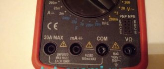
To determine the polarity, the multimeter must be turned on in the mode for measuring direct voltage up to 20 V. The wire of the black probe is connected to the socket marked COM (it corresponds to the negative pole), and the red one is connected to the socket with the VΩmA marker (it is, accordingly, a plus).
After this, the probes are connected to the wires or contacts and the device, the polarity of which needs to be determined, turns on. If the multimeter display shows a value without additional signs, then the poles are determined correctly, the contact to which the red probe is connected is positive, and the contact to which the black probe is connected will correspond to the minus. If the multimeter shows a voltage value with a minus sign, this will mean that the probes are connected to the device incorrectly and the red probe will be a minus, and the black probe will be a plus.
If the multimeter used to measure is analog (with an arrow and a display with gradations of values), if the poles are connected correctly, the arrow will show the actual voltage value, but if the poles are reversed, then the arrow will deviate in the opposite direction relative to zero, that is, it shows a negative current value.
Checking using special devices and tools
The main device for checking polarity is a multimeter. At home, it is easier to use an indicator screwdriver: it is inexpensive and convenient. However, the device does not always correctly determine the charge. If you don’t have any professional tools with you, and you urgently need to check the polarity, you can use an incandescent lamp or a battery with a speaker.
Indicator screwdriver
To determine the charge, you need to touch the metal part of the screwdriver to the wire or simply bring it to the voltage source.
If the LED lights up, you have a plus. No signal means minus. If the wire is disconnected from the network or broken, the indicator will not light even in phase.
False alarms most often result from friction between the housing and external surfaces, so this factor should be eliminated if possible.
Multimeter
To check the polarity, the multimeter is switched to DC voltage measurement mode (up to 20 V). The probe is connected to the COM socket, and the red wire is connected to the VmA connector. The latter acts as a phase. The dipstick is used as a minus.
After connecting the wires, check them with probes. A positive result is the appearance of numbers on the device screen. If the display does not react to what is happening or a minus sign appears, then you need to swap the cables. Some models use arrows for indication. The latter moves in the opposite direction if connected incorrectly.
Incandescent lamp
Regular battery
To test, you will need a AA battery and a speaker. The wires being tested are connected to different ends in turn. They are connected to the speaker for a few seconds. If the diffuser moves upward, then the wires are connected correctly. A slight downward sag indicates that the cables need to be swapped.
Determine visually
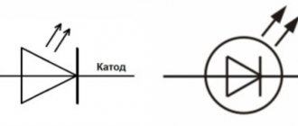
The first way is visual. Let's say you need to determine the polarity of a brand new LED with two leads. Look at its legs, that is, its conclusions. One of them will be shorter than the other. This is the cathode.
You can remember that this is a cathode by the word “short”, since both words begin with the letters “k”. The plus will correspond to the pin that is longer. Sometimes, however, it is difficult to determine the polarity by eye, especially when the legs are bent or have changed their sizes as a result of the previous installation.
Looking into the transparent case, you can see the crystal itself. It is located as if in a small cup on a stand. The output of this stand will be the cathode. On the cathode side you can also see a small notch, like a cut.
But these features are not always noticeable in LEDs, since some manufacturers deviate from the standards. In addition, there are many models made according to a different principle. Today, on complex structures, the manufacturer puts “+” and “−” signs, marking the cathode with a dot or a green line, so that everything is extremely clear. But if there are no such marks for some reason, then electrical testing comes to the rescue.
Color of wires plus (+) and minus (-) in DC networks
Is the red wire positive or negative? Such questions arise when working with DC electrical circuits.
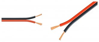
Red
To remember which plus is red or black, they use the name of a well-known international organization - the Red Cross. This phrase suggests that red means plus.
Black
Black color indicates the negative conductor. These markings can be seen on typical household equipment:
- power supplies;
- audio, video equipment;
- other devices with electronic software control units.
Plus
The polarity of conductors must be observed when repairing standard electrical equipment of cars. In some situations, confusion with plus and minus is accompanied by a violation of the functional state.
Minus
The high power of connected consumers increases the responsibility for performing repair and adjustment work. In such situations, it is necessary to eliminate errors in determining polarity. Strong direct current is used to supply electricity:
- warehouse and municipal transport;
- lifting mechanisms;
- sensors and automation.
Security measures
When working with electric current, the following precautions must be taken:
- Use devices only for their intended purpose;
- Do not turn on equipment with damaged wires and plugs, do not use faulty sockets;
- Do not touch wires or outlets with wet hands or while standing on a wet floor. When working in a room with high humidity, you need to use rubber gloves and a mat;
Working with electricity requires precautions
- Do not bend wires and cables;
- Before starting work, it is worth disconnecting the entire network;
- If the equipment sparks or starts to catch fire when turned on, do not touch it. It is necessary to turn off the power through the panel;
- If you have any doubts or fears, it is better to contact a specialist or choose a safer option, for example, determining the polarity using a potato rather than connecting to a device.
Most often in batteries, the red wire indicates positive, the black wire indicates negative, and there are no problems when working with electricity. However, today many countries use their own color designations or abandon them altogether, leaving the wires uniformly white. In order not to create emergency situations, it is worth checking the polarity first.
You may be interested in this All about current and its frequency
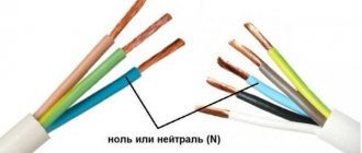
Marking of wires for alternating three-phase current
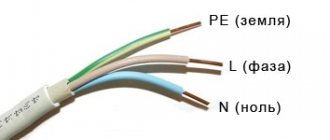
The special color designation of the shell helps to determine the purpose of individual lines even without studying the accompanying design documentation:
- gray, purple, orange or red wire – phase;
- yellow and green stripes – grounding;
- blue or a combination of white and blue stripes is neutral.
Such designations simplify installation operations when laying power lines, during the assembly of electrical panels
It is especially important to eliminate errors when hidden installation of communications inside building structures is used. In this case, correcting incorrect actions will be accompanied by increased costs
Determining polarity with a multimeter
Sometimes it happens that a new electrical device that needs to be connected does not have polarity markings or it is necessary to re-solder the wiring of a damaged device, and all the wires are the same color
In such a situation, it is important to correctly determine the poles of the wires or contacts
But if you have the necessary instruments, a logical question arises: how to determine the plus and minus of an electrical appliance with a multimeter?
To determine the polarity, the multimeter must be turned on in the mode for measuring direct voltage up to 20 V. The wire of the black probe is connected to the socket marked COM (it corresponds to the negative pole), and the red one is connected to the socket with the VΩmA marker (it is, accordingly, a plus).
After this, the probes are connected to the wires or contacts and the device, the polarity of which needs to be determined, turns on.
If the multimeter display shows a value without additional signs, then the poles are determined correctly, the contact to which the red probe is connected is positive, and the contact to which the black probe is connected will correspond to the minus.
If the multimeter shows a voltage value with a minus sign, this will mean that the probes are connected to the device incorrectly and the red probe will be a minus, and the black probe will be a plus.
If the multimeter used to measure is analog (with an arrow and a display with gradations of values), if the poles are connected correctly, the arrow will show the actual voltage value, but if the poles are reversed, then the arrow will deviate in the opposite direction relative to zero, that is, it shows a negative current value.
How to correctly determine the polarity on wires in a car
If the voltage on the car is checked, the course is set to search for a constant one. 20W is the correct setting if you are testing the battery. Therefore, you need to adjust the dial to the desired range/setting and connect the probes to whatever component you want to get a reading for.
You may be interested in this Features of active-capacitive load
How to check a headlight with a multimeter
Multimeter
To check the headlight wiring, you need to find the ground wire. There are 2-4 wires coming from the connector that connects to the light bulb. Where there are two or three wires, only one of them is ground, while four-wire connectors will have two grounds.
To test the wires on the headlight, you need to set the multimeter to resistance. You can place one of the probes on the ground and the other on the negative pole of the car battery.
Note! If continuity is not read, then there is a problem with the ground wire, meaning it needs to be replaced.
How to Test a Car's Ground Wire Using a Multimeter
To test ground wires, start by measuring resistance. Test along the wiring to check the reading is 5 ohms or less. If it exceeds, you will need to check the wire further. You need to switch the multimeter to constant voltage and turn on any electrical part that is having problems. It's worth double-checking the wire to make sure the reading doesn't exceed 0.05V. If it does, you'll need to use a different ground location or use a tie strap.
How to Check if a Fuse Has Blown Using a Multimeter
Troubleshooting a fuse using a multimeter is extremely easy. You need to set the multimeter to the lowest ohm setting and place the probes on both sides of the fuse covers. Fuses do not have polarity, so the contacts used will not show values.
Circuit breakers
Note! If the resistance value is very low, then the fuse is working perfectly. If the resistance value does not change after connecting the contacts, the fuse has blown.
You can also test the fuse using a test light. You need to turn on the key and touch both sides of the fuse with the tip of the test light. If it lights up, the fuse is good. If it does not light up, the fuse needs to be replaced.
How to use a multimeter from a car battery
If you're having trouble starting your car, one of the most common reasons is a weak battery. This is something that can be easily checked using a multimeter, which will also give an accurate idea of how much charge the battery actually has left. Testing your car battery first is a great way to rule out a likely cult for many electrical problems.
When testing a car battery, you need to check the voltage by setting the multimeter to 20 V DC. It is necessary to connect contacts to both terminals of the battery that match the color. It is better to turn on the headlights to get accurate information regarding the charge.
Important! The headlights must be turned on when the engine is stalled.
In most cases the reading will be somewhere between 11.8 V and 12.6 V. The higher the voltage reading, the more charge there is in the battery. A reading of 12.5V means the battery is almost fully charged, while a reading of 11.9V means the battery should be replaced soon.
You may be interested in this Features of free energy
Checking the charger
Electronic devices use adapters to convert alternating current supplied from wall outlets to direct current. Once converted to direct current, current flows in one direction, hence the term direct current.
What color is the positive wire on the charger?
Note! One wire is positive, which conducts current to the device, and the other is negative, which completes the circuit. The direction of flow is called polarity and is marked on chargers using a diagram. If there is no diagram on the charger, it is worth checking the polarity.
The color polarity of the charger wires does not matter.
To determine if the charger is fit for use, do the following:
- Connect the charger to a power outlet.
- Turn on the multimeter and set the settings to DC voltage. Most multimeters indicate this setting as VDC.
- Insert the red positive contact into the hole in the charger tip.
- Touch the black negative terminal and the outer metal part of the charger tip.
- Monitor the multimeter readings. You may see a positive or negative number indicating the DC output voltage of the charger. If the number is positive, then the polarity on the inside of the charger tip is positive. If the number is negative, then the polarity inside is negative.
Letter designation of wires
Color markings can be supplemented by letters. Partially the symbols for the designation are standardized:
- L (from the word Line) – phase wire;
- N (from the word Neutral) – neutral wire;
- PE (from the combination Protective Earthing) - grounding;
- “+” – positive pole;
- “-” – negative pole;
- M – midpoint in DC circuits with bipolar power supply.
To designate the protective grounding connection terminals, a special symbol is used, which is stamped on the terminal or on the device body in the form of a sticker. The grounding symbol is the same for most countries in the world, which reduces the likelihood of confusion.
In multiphase networks, the symbols are supplemented by the serial number of the phase:
- L1 – first phase;
- L2 – second phase;
- L3 – third phase.
There is marking according to old standards, when the phases are designated by the symbols A, B and C.
A deviation from the standards is the combined phase designation system:
- La – first phase;
- Lb – second phase;
- Lc – third phase.
In complex devices, additional symbols may be found that characterize the name or number of the circuit
It is important that the markings of the conductors match throughout the entire circuit where they are involved
Letter designations are applied with indelible, clearly visible paint on the insulation near the ends of the cores, on sections of PVC insulation or heat-shrinkable tube.
Connection terminals may have marks that indicate circuits and power polarities. Such signs are made by painting, stamping or etching, depending on the material used.
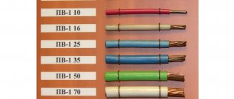
Wire Classification Options
Before you understand the decoding of the markings, it is recommended that you familiarize yourself with the parameters by which the wires are divided:
- Number of cores Depending on this parameter, the cable can be used to ensure the operation of electric motors, for wiring in a house or apartment, for transmitting current in power networks.
- Current-carrying conductor material. The materials most often used in electrical applications are copper and aluminum or a combination of these metals.
- Insulation. Wires can be with or without insulation. Bare conductors provide communication for power lines. Insulated ones are laid in places where there is a possibility of exposure to external factors such as wind, water, dust or snow. Plastic, rubber, lead, paper and many other materials are used as insulation.
- Cable section. Using this indicator, you can determine the strength of alternating or direct current that will pass through the conductors.
- Other indicators. Resistance, power and voltage indicators are very important for network wiring and connecting various devices.
Knowing which conductors are responsible for the loads, you can correctly connect to the meter, repair the wiring, connect the oxygen sensor in the car, etc.
Yellow-green grounding
The grounding conductor, or earth, serves for safety. The name comes from the fact that through this connection a dangerous charge (for example, formed on the body of a faulty device) instantly flows into the ground. Thus, grounding protects a person from electric shock.
There may not be a grounding wire in single-phase networks of old buildings, but this is becoming less and less common - during repairs, electricians recommend and install a network with ground.
Most often, the insulation of the ground wire is yellow-green. Sometimes the wire is only yellow or white with a green stripe. Grounding is marked with the letters “PE” - from the English “protective earthing” (protective grounding). But on diagrams, housings and terminal blocks it may be indicated not by letters, but by special symbols (see table).
ADVICE:
There is no complete guarantee that the wires in your home are connected in accordance with the colors - the human factor occurs in any area. In addition, the insulation of the wires may be the same color. In this case, you can also handle it yourself - an indicator screwdriver will help. This is a very simple tool that can be purchased at almost any hardware store.
The transparent handle of this screwdriver has a neon light or LED. At the end of the handle there is a contact plate on which you need to keep your finger during testing. If you touch the exposed wire of a live phase with a metal tip (probe) of a screwdriver, the light bulb will light up, but if there is no zero wire, it will not.
Capacitor Characteristics
The main characteristic of any capacitor is its capacity, which determines the amount of accumulated charge. The capacitance depends on the area of the plates and the thickness of the dielectric layer.
Attention! The area of the plates cannot be increased indefinitely, as this leads to an increase in the dimensions and weight of the device. The thickness of the dielectric layer can also be reduced only to a certain value, since any insulator has its own electrical strength limit
In this regard, the second main characteristic is the operating voltage at which the capacitor retains its properties throughout its entire service life
The thickness of the dielectric layer can also be reduced only to a certain value, since any insulator has its own electrical strength limit. In this regard, the second main characteristic is the operating voltage at which the capacitor retains its properties throughout its entire service life.
Exceeding the operating voltage leads to electrical breakdown and malfunction of the device, in particular, in some applications it is necessary to take into account additional parameters, namely:
- Temperature coefficient, which takes into account the effect of heating on the capacity of the radio element;
- Dielectric loss tangent, characterizing the properties of a radio element when operating at high frequencies;
- Switching polarity, which arises due to the design features of certain types of devices.
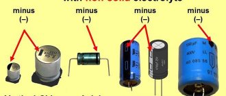
To increase the capacity while maintaining acceptable dimensions, it is necessary to apply various technical subtleties. For example, in electrolytic capacitors, a narrow and long strip of aluminum foil is used as one of the plates. A thin layer of oxide on the surface of the foil acts as an insulator, and a liquid electrolyte is used instead of a second plate. To make such a capacitor, a sheet of foil is rolled into a thin cylinder, which is then placed in the housing.
Electrolytic capacitor
This design combines a large plate area and a small dielectric thickness, which makes it possible to obtain very large capacitance values with small dimensions.
The main disadvantage of such capacitors is the need to strictly observe the polarity of the connection. Failure to comply with this requirement leads to high currents, leaks and structural failure. Electrolytic capacitors must have polarity markings for proper connection.
Color of wires plus ( ) and minus (-) in DC networks
Is the red wire positive or negative? Such questions arise when working with DC electrical circuits.
Red
To remember which plus is red or black, they use the name of a well-known international organization - the Red Cross. This phrase suggests that red means plus.
Black
Black color indicates the negative conductor. These markings can be seen on typical household equipment:
- power supplies;
- audio, video equipment;
- other devices with electronic software control units.
The polarity of conductors must be observed when repairing standard electrical equipment of cars. In some situations, confusion with plus and minus is accompanied by a violation of the functional state.
The high power of connected consumers increases the responsibility for performing repair and adjustment work. In such situations, it is necessary to eliminate errors in determining polarity. Strong direct current is used to supply electricity:
- warehouse and municipal transport;
- lifting mechanisms;
- sensors and automation.
Something to remember! Domestic standards have changed several times over the past decades. Currently, the markings discussed above are used.
https://www.youtube.com/watch?v=channelUChB8KhWMvtTMXpi-zgHx5FQ
The color options for the shells will help you recognize the intended purpose of the conductors:
- blue – working zero;
- transverse or longitudinal combinations of yellow and green stripes - protective zero;
- main blue with a change to a combination of yellow and green stripes at the junctions - combined working and protective zero.
For your information. The last universal option can be done in the reverse way. The main part of the line is created from a combination of yellow and green stripes, with blue color applied at the junctions.
Checking polarity
AC current can be tested using a multimeter or ohm voltmeter. Testing with a multimeter usually involves touching the positive and negative leads from the meter to the wiring being tested.
Voltmeter
Note! A flashing negative sign ("-") before the digital readout on the meter indicates incorrect polarity
Reverse polarity
If one of the outlets in your home is found to have reverse polarity, it is not difficult to correct the problem, but you will need to be careful to avoid electrocution. Before inspecting the wiring, you must turn off the household power supply. The positive wires, which are usually red or black, should be connected to a brass terminal. The neutral wires, which are usually white or gray, should be connected to a light-colored chrome terminal.
Important! If the wires are connected incorrectly, the polarity will be reversed, causing the current to flow in the opposite direction. This could result in electric shock to anyone who touches the device or outlet, and even damage to the device itself.
White, black, blue: which phase is connected
Electrics do not forgive mistakes. Identification by color will pleasantly reduce repair time and possible treatment costs. The phase wire is most often red or black. White, brown, purple, pink, gray and orange shades are equally dangerous. Which one is a “plus” and which one is a “minus” is easy to confuse.
In electrical networks, all this color variety is the designation of a phase conductor. Which wire color is responsible for what is indicated in the list. It can be completed with a turquoise color scheme, and the colors of the most dangerous wires are listed.
Knowledge of wire markings is necessary to safely carry out electrical wiring repairs.
If the information about what the black or red wire means is easy to remember, then the remaining color intricacies, where it is easy to make a mistake, can be figured out using a screwdriver with an indicator. A light signal at the end of the device will allow you to understand which conductor is responsible for phase and neutral, and which is grounding.
How to determine ground, zero and phase on wires if there are no markings
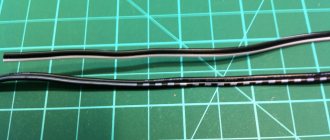
It is more difficult to determine in practice than in theory. Not all manufacturers comply with the standards. Therefore, when laying a two-phase 220 V network with grounding, you have to use a VVG cable with blue, brown and red colors. Combinations may be different, but without complying with regulatory requirements.
For your information. In old wiring from “Soviet times” there is no color marking. Identical white (gray) shells do not allow the purpose and correspondence of the lines to be known by simple visual inspection.
To avoid problems, it is recommended to carry out installation work using the same type of cable products. When color coding is not available, it should be created at the joints using insulating tape or heat shrink tubing. The latter option is preferable, as it is designed to maintain integrity for a long time.
Below are methods for determining phase and neutral wires with the advantages and disadvantages of each option. In any case, first clarify the network parameters. In old houses, for example, a two-wire connection scheme with a single working and grounding conductor is often used.
The figure shows a modern network with separate grounding and working zero connections. It is possible to connect three- and single-phase loads.
Determining the phase using an indicator screwdriver
Touching the tip of such a device to the phase wire closes the current circuit. This is accompanied by the warning lamp or LED lighting up. A built-in resistor limits the current to a safe level.
Advantages of the indicator:
- minimum cost;
- compactness;
- reliability;
- durability;
- autonomy;
- good protection from adverse external influences.
The disadvantage is the limited measurement accuracy. Under certain conditions, false positives cannot be ruled out.
Determination of ground, zero and phase using a test lamp
To reproduce this technology, you need to prepare a simple design. An incandescent lamp designed for the appropriate mains voltage is screwed into a standard socket. Connect wires of sufficient length to perform work operations in a specific location.
Next, connect one of the wires to the known zero line. Others sequentially check other cable cores. Lighting of the lamp indicates the presence of a phase.
Using a measuring device
When checking a 220 V household network, you do not need to know how to determine the polarity. The power supply is organized using alternating current, so set the multimeter switch to the appropriate position. Touching the phase-zero (phase-ground) wires with the probes is accompanied by an indication of the corresponding voltage (≈220 V). The potential difference between the neutral conductor and ground is minimal.
For your information. When checking an old two-wire circuit, one of the probes touches the reinforcement in a concrete slab, a radiator of a heating system, or another grounded element of a building structure.
When switching to constant voltage, the multimeter will show where the plus and minus are. In the absence of reliable information about the electrical parameters in the circuit, they begin with the maximum measurement range with a sequential transition to smaller values with insufficient accuracy.
Such a “device” is useful for testing DC circuits in the absence of specialized measuring instruments. Bubbles near the negative wire are the release of hydrogen during the electrolysis reaction. The area near the plus will take on a greenish tint after a few minutes.
Using LED
You can create a control device with your own hands by analogy with an indicator screwdriver. Instead of a light bulb, install AL 307 or another LED with similar characteristics. A 100-120 kOhm resistor with a power of 1-2 W is added in series to the circuit.
How to check the correctness of marking and wiring
Wire colors in electrical engineering are designed to speed up the identification of conductors, but relying only on colors is dangerous - they could be connected incorrectly. Therefore, before starting work, you should make sure that you have correctly identified their affiliation.
Take a multimeter and/or an indicator screwdriver. It’s easy to work with a screwdriver: when you touch a phase, the LED built into the housing lights up. So it will be easy to identify phase conductors. If the cable is two-wire, there are no problems - the second conductor is zero. But if the wire is three-wire, you will need a multimeter or tester - with their help we will determine which of the remaining two is phase and which is zero.
Determining the phase wire using an indicator screwdriver
We set the switch on the device so that the selected jackal is more than 220 V. Then we take two probes, hold them by the plastic handles, carefully touch the metal rod of one probe to the found phase wire, the second to the supposed zero. The screen should display 220 V or the current voltage. In fact, it may be significantly lower - this is our reality.
If 220 V or a little more is displayed, this is zero, and the other wire is presumably “ground”. If the value is less, we continue checking. With one probe we again touch the phase, with the second - to the intended grounding. If the instrument readings are lower than during the first measurement, there is “ground” in front of you and it should be green. If the readings turn out to be higher, it means that somewhere there was a mistake with “zero” in front of you. In such a situation, there are two options: look for exactly where the wires were connected incorrectly (preferable) or simply move on, remembering or noting the existing position.
So, remember that when testing a phase-zero pair, the multimeter readings are always higher than when testing a phase-ground pair.
And, in conclusion, let me give you some advice: when laying wiring and connecting wires, always connect conductors of the same color, do not confuse them. This can lead to disastrous results - at best, equipment failure, but there may also be injuries and fires.
Colors for 220V and 380V networks
Installation of single- and three-phase electrical networks is facilitated if the wiring is made with multi-color wire. Previously, a flat two-core white wire was used for single-phase residential wiring. During installation and repair, to eliminate errors, it was necessary to ring each core individually.
The production of cable products with colored cores in different colors reduces the labor intensity of the work. To indicate phase and zero in single-phase wiring, it is customary to use the following colors:
- red, brown or black – phase wire;
- other colors (preferably blue) – neutral wire.
The phase markings in a three-phase network are slightly different:
- red (brown) – 1 phase;
- black – 2 phase;
- gray (white) – 3 phase;
- blue (cyan) – working zero (neutral)
- yellow-green – grounding.
Domestic cable products comply with the standard for core coloring, so a multiphase cable contains differently colored cores, where the phase is white, red and black, the neutral is blue, and the ground is yellow-green conductors.
When servicing networks installed according to modern standards, it is possible to accurately determine the purpose of the wires in the junction boxes. If there is a bundle of multi-colored wires, the brown one will definitely be phase. The neutral wire in distribution boxes has no branches or breaks. The exception is branches to multi-pole switching devices with complete circuit breaking.
Wire colors in single-phase and three-phase networks
The disadvantage of single-color wiring is the difficulty of finding zero and phase. In order not to regularly use an indicator and a multimeter in single-phase and three-phase lines, a distinction is made by the color of the cables. Such networks are installed in home areas with low load on the electrical network. The list of colors for electrical conductors and their designation by letters are given in the text of GOST 28.763 - 1998.
Single-phase two-cable system:
- Use a two-core conductor with cores of different colors or install two single-core cables.
- Flexible wires with blue (blue) and brown braiding are often used.
- For phase, take a brown color, paint the zero blue.
A three-wire system is a network that uses three wires. In new buildings, such a network is often found. There is a phase neutral conductor in the line, the third is a grounding conductor against electric shock. The color of the first wire is brown, black, the second is blue, and the third is yellow-green.
Three-phase 380V circuits are installed when connecting sockets that have an additional contact for connection to the grounding conductor. Such networks conduct electricity through a three, four or five-core cable. They may have three phase wires and may or may not have a grounding contact. The phase has a braid of brown, black, grey, red, orange or purple.
What color are the poles in the wires?
The protective neutral cable connects the protective ground and N-neutral cables. These types require double grounding along the line. The marking of electrical wires is the same as for the protective conductor, yellow-green. Blue color was also used in older installations, but nowadays such markings are rare. It is much more common to see installations marked with alternative yellow and green stripes.
Note! The very tip of the protective neutral cable is usually marked blue. Neutral cable is found in very old electrical installations
It was used in cases where circuits did not yet have neutral and protective cables. The installation only had phase and ground neutral wires, which could be identified by their blue color. Today the neutral conductor is no longer used in electrical installations
The neutral cable is found in very old electrical installations. It was used in cases where circuits did not yet have neutral and protective cables. The installation only had phase and ground neutral wires, which could be identified by their blue color. Today, the neutral conductor is no longer used in electrical installations.
Green cable with positive potential
Green color is for electrical cables with positive potential.
In electronic devices, positive charge flows in the red wires, negative charge in the black wires.
Coloring of the neutral wire
What color is the neutral wire?
Blue or cyan It is generally accepted that the neutral wire should be blue or light blue, or blue with a white stripe. To avoid confusion, only a conductor of this color is used as a neutral conductor, regardless of how many conductors the cable has.
In the diagrams, the neutral conductor is also drawn in blue or light blue, marked with the letter “N”. This conductor has nothing to do with the protective or grounding conductor, since, together with the phase conductor, it is an integral part of the electrical circuit.
Some “professionals” call the phase wire “plus” and the zero wire “minus”, which misleads others by confusing an alternating electrical circuit with a constant one, where “plus” and “minus” are taken as the basis.
What color are the wires phase, neutral and ground. Color marking of wires.
Watch this video on YouTube
Description of poles
In the case of an electric current passing between two points, or poles, one of the poles will have more electrons than the other. The pole with more electrons is said to have a negative charge. The pole with fewer electrons has a positive charge. When two poles are connected by a wire, electrons move from the negative pole to the positive pole. This flow is called electric current.
Polarity can be of different types
For your information! In a DC circuit, one pole is always negative and the other positive with electrons flowing in only one direction. In an alternating current (AC) circuit, the two poles alternate between negative and positive poles with the electrons flowing in the opposite direction.
Neutral color
What color the neutral wire is is specified by GOST , so when looking at the installation of a power plant, the question should not arise whether the blue wire is a phase or a zero, since the blue color and its shades (blue) are accepted to indicate neutral (working grounding).
Other colors of neutral cores are not permitted.
The only acceptable use of blue and cyan insulation is to indicate the negative pole or midpoint in DC circuits. This color cannot be used anywhere else.
Ground wire color
By modern standards, the ground conductor is yellow-green. It usually looks like yellow insulation with one or two longitudinal bright green stripes. But there are also transverse yellow-green stripes in color.
Grounding may be this color
In some cases, the cable may only have yellow or bright green conductors. In this case, the “earth” has exactly this color. It is displayed in the same colors on diagrams - most often bright green, but it can also be yellow. Signed on circuit diagrams or on ground equipment in Latin (English) letters PE. The contacts to which the “ground” wire must be connected are also marked.
Sometimes professionals call the grounding wire “neutral protective”, but do not be confused. This is an earthen one, and it is protective because it reduces the risk of electric shock.
Why do we need color coding for wires and cables?
Installation and maintenance work in electrical installations is associated not only with ensuring reliability, but also safety. Complete error elimination is required. For these purposes, a system of color designations for core insulation has been developed, which determines what color the wires are phase, neutral and ground.
According to the PUE, the following colors of current-carrying conductors are allowed:
The above list contains many options for wire colors, but there are not several colors that are used only to indicate neutral and protective wires:
- blue color and its shades – working neutral wire (neutral – N);
- yellow with a green stripe – protective earth (PE);
- yellow-green insulation with blue marks at the ends of the conductors - combined (PEN) conductor.
It is allowed to use conductors with green insulation with a yellow stripe for grounding, and for combined conductors blue insulation with yellow-green marks at the ends.
The color must be the same in each circuit within one device. Branch circuits must be made with identically colored conductors. The use of insulation without differences in shades indicates a high standard of installation and greatly facilitates further maintenance and repair of equipment.
Wire marking
Wire marking is the application of a specific mark to their outer surface to indicate the required characteristics. Marking can be in the form of color markings, inscriptions (numbers and letters), labels or tags.
Important! Letter or numerical markings indicate the material of the shell and cores, cross-sectional area, number of cores inside and other parameters. The red wire indicates the positive phase or plus
You can remember it by the name “Red Cross”. Black corresponds to negative phase
The red wire indicates the positive phase or plus. You can remember it by the name “Red Cross”. Black corresponds to the negative phase.
But this designation does not always work: the colors may be different, for example, green and blue, or absent altogether. There are many more colors in three-phase wires:
- The phase is indicated by red, orange, purple or gray colors:
- Neutral - blue or white-blue;
- Grounding - stripes of green or yellow colors.
To avoid mistakes during installation, if in doubt, it is better to check the polarity in advance.
How to visually understand where the plus and minus are
Sometimes manufacturers put markings on the wires. However, in most cases there are no special markings on the cables. The main method for determining the polarity of wires remains checking the color of the braid.
By labeling
In rare cases, you can find a factory designation on the wire in the form of a plus or minus. However, most often the polarity is not indicated in the markings. Manufacturers prefer to use color codes.
The main marking lists the type of cores, their number, cross-section, working purpose, etc.
By wire color
The phase, i.e. plus, is usually indicated with bright colors. Most often it is red. Sometimes orange, purple and yellow shades are used.
Zero, i.e. minus, is marked in white, grey, black or blue. However, exceptions are possible depending on the country of origin. For example, in the USA and Canada the phase conductor may be black. Green in most cases indicates grounding. The table below shows the most common options in different regions.
| Country or region | Phase conductor colors | Neutral conductor color | Protective conductor color |
| USA | Black, brown, red, purple, blue and yellow | Gray or silver | Green |
| Canada | Red, orange, black, brown, blue and yellow | White | Green or without braid |
| Pakistan and India | Yellow, white, red and blue | Black | Green or yellow-green |
| Europe | Brown, black and gray | Blue | Yellow-green |
| Norway | Black, brown, white and gray | Blue | Yellow-green, green or unbraided |
| USSR | Green, yellow, red | Blue | Yellow-green, rarely black |
| China, Russia, Belarus, Ukraine and Kazakhstan | Green, yellow, red | Blue | Yellow-green |