A resistor is an element used in an electrical circuit and does not require a power source for its operation. It is designed to transform current into voltage and vice versa. In addition, it can convert electrical energy into thermal energy and limit the amount of current. But before calculating the voltage drop across a resistor, it is advisable to understand the essence of this process.
A resistor is a very common element characterized by a number of parameters. The main ones are:
Resistors can be produced with constant and variable resistance. A type of the latter are tuning elements. The only difference between them and variables is the way they are set to the desired value.
On diagrams and in technical literature, the device is designated by the Latin letter R, next to which the serial number and its denomination are indicated in accordance with the International System of Units (SI). For example, R12 5 kOhm is a five kilo-ohm resistor located in the circuit under number 12.
When manufacturing an element, a resistive layer is used, which can be film or volumetric. It is applied to a dielectric base and covered with a protective film on top.
Resistance value
In fact, the resistance of an element is determined by its physical structure and is caused by the vibrations of atoms in the crystal lattice. Therefore, all materials are classified as conductors, semiconductors and dielectrics depending on their ability to conduct electricity.
But Ohm's law cannot be applied to all substances. In electrolytes, dielectrics and semiconductors, a linear relationship between the three quantities is not always observed. The resistance of such substances depends on the physical parameters of the conductor, namely its length and cross-sectional area, and it is sensitive to temperature changes.
This dependence is described using the formula R = p * l / S. That is, the resistance is directly proportional to the length and inversely proportional to the area of the conductor. The value p is called resistivity and is determined by the type of material. Its meaning is taken from the reference book.
Resistor impedance
Ohm's law applies to an ideal resistor that has no parasitic resistance. The total resistance (impedance) is determined based on the equivalent circuit. Accurate calculation of resistance to reduce voltage must be carried out using other formulas. The equivalent circuit of a resistor, in addition to active impedance, also contains capacitive and inductive reactance.
What kind of lighting do you prefer?
Built-in Chandelier
Impedance is calculated using the formula : I = U/Z, where Z = (R2+(Xc-Xl)2)½. Where:
Knowing the total resistance of the resistor, you can more accurately calculate the voltage drop in it. But to measure parasitic components you will need to use highly specialized instruments. In conventional calculations, resistance is calculated taking into account only its active value, and parasitic values are taken as negligible.
Voltage divider using resistors: calculation, theory and principle of operation
The main function of a voltage divider in electrical circuits is to reduce the voltage and obtain several of its values with fixed values in different areas. It is based on resistors or reactances in the amount of two or more elements.
Expert opinion
Viktor Pavlovich Strebizh, lighting and electrical expert
Any questions ask me, I will help!
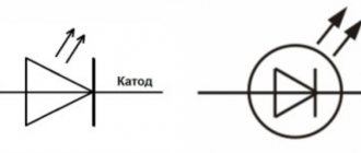
It doesn’t matter which side the resistance is facing, unlike diodes, resistors pass current equally in both directions. If there is something you don’t understand, write to me!
How to lower voltage using a resistor
To prevent the load that needs to be powered from burning out, it is often necessary to reduce the input voltage. The easiest way to achieve this is to use a two-resistor circuit, better known as a voltage divider. The classic scheme looks like this:
In this case, the voltage is supplied to two resistors using a parallel connection, and at the output it is received from one. The selection of resistor values is carried out according to the formula so that the voltage removed at the output is some part of the supplied one. You can calculate a resistor to reduce the voltage using a formula based on Ohm's law:
Selecting a resistor to reduce voltage
There are also a number of free emulation programs that allow you to perform, among other things, calculations of a resistor when the voltage drops, for example:
In the article, we became acquainted with the concept of resistance, learned about its units of measurement, the marking of resistors, programs that emulate the operation of a circuit and facilitate the selection of the desired resistance, and also looked at examples of calculating the voltage drop across a resistor.
Current flowing in a circuit of parallel connected resistors
When considering the corresponding sections of branched circuits, it is necessary to remember that the currents at the input and output of each node are equal, as well as before and after the group of parallel resistors. This rule will help check the correctness of the calculations. If the marked correspondence is not met, the calculation error is eliminated.
Using the initial data discussed above for two complex circuits, a calculation can be made for each individual branch.
Example 1:
- the total current in the circuit is 0.8 A;
- the distribution of voltages in individual sections is easy to determine from the calculated equivalent resistances: U12 = I * Req1 = 0.8 * (2*4)/ (2 4) = 0.8 * 1.3 = 1.04 V;
- The current values are calculated using the standard algorithm: I1 = U12/R1 = 0.52 A, I2 = U12/R2 = 0.26 A;
- summation checks the correctness of the calculations: I = I1 I2 = 0.52 0.26 ≈ 0.8 A.
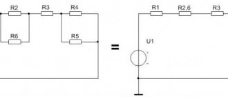
Example 2 (mixed method of connecting resistors):
- current in this version is 1.2 A;
- the voltage in the section with a group of parallel resistors is Uab = I * Reeq(12345) = 1.2*2.5 = 3V;
- By analogy with the previous example, it is easy to calculate the current in each individual branch: I12 = Uav/(R1 R2) = 3/ (15 5) = 0.15 A;
- I3 = Uav/ R3 = 3/ 5 = 0.6 A;
- I4 = Uav/ R4 = 3/ 10 = 0.3 A;
- I5 = Uav/ R5 = 3/20 = 0.15 A;
- According to the rule of equality of currents at the input and output of the node, the correctness of the calculations made is checked: I = I12 I3 I4 I5 = 0.15 0.6 0.3 0.15 = 1.2 A.
READ MORE: Do-it-yourself septic tank made from tires, step-by-step instructions
P = I2 *R = U2/ R.
For your information. The design of each element is designed for a specific operating temperature range. Exceeding the threshold can destroy the part, the soldering point, and neighboring components. One should not forget about a simultaneous significant change in resistance, which can disrupt the functional state of the electrical circuit.
For the calculation, select a suitable formula taking into account the known initial parameters (data from example 2 in the previous section):
- current – 1.2 A;
- at resistance R6=7.5 Ohm the power dissipation will be: P6 = I2 *R = 1.44 * 7.5 = 10.8 W;
- It is difficult to find such a resistor, since the standard range offers ratings from 0.05 to 5 W;
- in another circuit (R5=20 Ohm) the calculated current will be 0.15 A, so P5= 0.0225 * 20 = 0.45 W;
- in this case, you can choose a product with a suitable dissipation power in the standard range of 0.5 W (experts recommend making a 1.52-fold margin, so it is better to use a 1 W resistor).
Standard symbols on electrical diagrams and typical power ratings
For your information. When choosing resistors, you should take into account the product class in terms of electrical resistance accuracy. In serial parts, deviations of 5-20% are acceptable.
Select the appropriate option (combination) taking into account the available initial data. It should be remembered that there is a single voltage at the input and output and different currents in individual branches. Computing technology is discussed in previous sections.
The total current I flowing in a circuit of parallel resistors is equal to the sum of the individual currents flowing in all parallel branches, and the current in a single branch does not necessarily have to be equal to the current in adjacent branches.
Despite the parallel connection, the same voltage is applied to each resistor. And since the value of resistance in a parallel circuit can be different, the amount of current flowing through each resistor will also be different (as defined by Ohm’s law).
Let's consider this using the example of two resistors connected in parallel. The current that flows through each of the resistors (I1 and I2) will be different from each other since the resistances of resistors R1 and R2 are not equal. However, we know that the current that enters the circuit at point "A" must leave the circuit at point " B"
I = I1 I2
Current flowing in R1 = U ÷ R1 = 12 ÷ 22 kOhm = 0.545 mA
Current flowing in R 2 = U ÷ R2 = 12 ÷ 47 kOhm = 0.255 mA
I = 0.545 mA 0.255 mA = 0.8 mA
I = U ÷ R = 12 V ÷ 15 kOhm = 0.8 mA (same)
where 15 kOhm is the total resistance of two parallel connected resistors (22 kOhm and 47 kOhm)
And in conclusion, I would like to note that most modern resistors are marked with colored stripes and their purpose can be found out here.
Parallel connection
With this switching on, the current passing through the node begins to split, and a different value will flow through each element. The amount of current in each element will be directly proportional to the resistance of the resistor, so the total conductivity in this section will increase, and its impedance will decrease.
The formula with which you can calculate the total conductivity looks like this: G = 1/ Rtot = 1/ R1 + 1/ R2 +…+ 1/ Rn, where n denotes the serial number of the resistor in the circuit.
Transforming this formula, you get an expression of the form: R total = 1/G = (R1*R2*…* Rn) / (R1*R2 + R2*Rn +…+ R1*Rn. Having analyzed it, we can conclude that with parallel connection, the impedance will always be less than the smallest value of an individual resistor.
With such a connection, the voltage between the nodes is simultaneously the total potential difference for the entire section and at each individual resistor. Therefore, if you calculate the voltage drop on one device, then it will be the same on any parallel-connected element: U total = U 1 = U 2 =...= U n.
But the electric current passing through a separate element, based on Ohm’s law, will be equal to: I Rn = U Rn / R n.
How to calculate resistance for voltage drop: resistor drop formula, online calculator
It should be noted that the use of pull-down resistors is only used for low-power loads, since some of the energy is converted into heat and the coefficient of performance (COP) is very low.
Expert opinion
Viktor Pavlovich Strebizh, lighting and electrical expert
Any questions ask me, I will help!
The potential difference drop across the first element is calculated as U 1 1000 12 1000 1000 6 V, and the total voltage Utot U 1 U 2 12 V, which corresponds to the value of the power source. If there is something you don’t understand, write to me!
Resistance dependence
The value of electrical conductivity depends on several factors that must be taken into account when calculating, manufacturing resistive load elements (resistors), repairing and designing devices. These factors include the following:
- Ambient and material temperature.
- Electrical quantities.
- Geometric properties of matter.
- The type of material from which the conductor (semiconductor) is made.
Electrical quantities include potential difference (voltage), electromotive force (EMF) and current. The geometry of a conductor is its length and cross-sectional area.
Electrical quantities
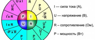
The dependence of electrical conductivity on electrical parameters is determined by Ohm's law. There are two formulations: one for a section, and the other for a complete chain. In the first case, the ratio is determined based on the values of current (I) and voltage (U) by a simple formula: I = U / R. From the ratio one can see that the current is directly proportional to the voltage value, as well as inversely proportional to the resistance. You can express R: R = U / I.
You might be interested in The work of third-party forces in a DC circuit and sources of EMF
To calculate the electrical conductivity of the entire section, you should use the relationship between the emf (e), current strength (i), and also the internal resistance of the power source (Rin): i = e / (R+Rin). In this case, the value of R is calculated using the formula: R = (e / i) - Rin. However, when performing calculations, it is also necessary to take into account geometric parameters and the type of conductor, since they can significantly affect the calculations.
Type and geometric parameters
The property of a substance to conduct electricity is determined by the structure of the crystal lattice, as well as the number of free carriers. Based on this, the type of substance is the key factor that determines the amount of electrical conductivity. In science, the coefficient that determines the type of substance is denoted by the letter “p” and is called resistivity. Its value for various materials (at a temperature of +20 degrees Celsius) can be found in special tables.
Sometimes, for convenience of calculations, the inverse quantity is used, which is called specific conductivity (σ). It is related to resistivity by the following relationship: p = 1 / σ. Cross-sectional area (S) affects electrical resistance. From a physical point of view, the dependence can be understood as follows: with a small cross section, more frequent interactions of electric current particles with the nodes of the crystal lattice occur. The cross section can be calculated using a special algorithm:
- Measuring the geometric parameters of the conductor (diameter or side length) using a caliper.
- Visually determine the shape of the material.
- Calculate the cross-sectional area using the formula found in a reference book or on the Internet.
In the case when the conductor has a complex structure, it is necessary to calculate the value S of one element, and then multiply the result by the number of elements included in its composition. For example, if the wire is multi-core, then S should be calculated for one wire. After this, you need to multiply the resulting value S by the number of cores. The dependence of R on the above values can be written as a ratio: R = p * L / S. The letter “L” is the length of the conductor. However, to obtain accurate calculations, it is necessary to take into account the temperature indicators of the external environment and the conductor.
Temperature indicators
There is evidence that the resistivity of a material depends on temperature, based on physical experiment. To conduct the experiment, you need to assemble an electrical circuit consisting of the following elements: a power source, a nichrome spiral, connecting wires of an ammeter and a voltmeter. Instruments are needed to measure current and voltage values, respectively. When electricity flows, the nichrome spring heats up. As it heats up, the ammeter readings decrease. In this case, a significant voltage drop occurs in the circuit section, as evidenced by the voltmeter readings.
You might be interested in this: The concept and determination of electrical power using formulas
In radio engineering, a decrease in voltage is called a sag or drop. The formula for the dependence of p on temperature is as follows: p = p0 * [1 + a * (t - 20)]. The value p0 is the resistivity of the material taken from the table, and the letter “t” is the temperature of the conductor.
The temperature coefficient “a” takes the following values: for metals - a>0, and for electrolytic solutions - a<0. To obtain a formula that determines all dependencies, it is necessary to substitute all relationships into the general formula for the dependence of R on the type of material, temperature, length and cross-section: R = p0 * [1 + a * (t - 20)] * L / S. Formulas are used only for calculations and manufacture of resistors. An ohmmeter is used to quickly measure the resistance value.
Serial connection
This is the name for combining two or more resistors into one section of a circuit, in which their connection to each other occurs only at one point. Impedance when connected in series is defined as the sum of the resistances of each individual element: Rtotal = R1+R2+…+Rn.
Consequently, the current flowing through such a chain will become less and less after passing through a series-connected resistor. The more elements there are in the chain, the more difficult it will be for him to pass them all. Thus, its overall value is determined as Itotal = U / (R1+R2+…+Rn).
Therefore, it can be argued that in a series connection there is only one path for current to flow. The greater the number of resistors in the line, the less current will be in this section.
The drop in potential difference with this type of connection on each element will have its own meaning. It is determined by the formula URn = IRn*Rn, and the greater the impedance of the element, the more energy it will begin to release.
Useful tips Connection diagrams Principles of operation of devices Main concepts Meters from Energomer Precautions Incandescent lamps Video instructions for the master Testing with a multimeter
What is a resistor
A resistor is an electronic component that has a specific, never changing electrical resistance. The resistance of the resistor limits the flow of electrons through the circuit. A resistor is a passive component, i.e. it only consumes energy (does not generate it).
Resistors are usually added to a circuit where they complement active components such as op-amps, transistors, microcontrollers, etc.
Typically, resistors are used for current limiting, in voltage divider circuits, and as pull-up resistors on the I/O line. There are several types of resistors.
Resistor characteristics
Since the main purpose of a resistor is to limit the flow of electric current, its key parameter, of course, is resistance. In the production of resistors, the accuracy of the nominal value (deviation from the nominal value) is indicated as a percentage.
There are also other parameters that characterize the operation of the resistor under certain conditions, for example, the temperature coefficient of resistance, the inductance and capacitance of the resistor, the electrical noise of the resistor.
The temperature coefficient is usually taken into account when it is necessary to achieve high resistance stability, which is determined by the type of resistive material, as well as the design of the resistor itself.
In high frequency circuits, such as RF circuits, the capacitance and inductance of a resistor can have undesirable effects. Foil resistors tend to have low parasitic reactance, while wirewound resistors are among the worst.
In audio amplifier circuits, the electrical noise of the resistor should be kept to a minimum level.
Electrical noise is measured in microvolts per volt of applied voltage for a 1 MHz bandwidth. Pages: 1