Small transformerless power supplies are often used to power low-power devices from a 220 V network. If the current consumed by the load is on the order of several tens of milliamps, you can easily convert the AC input voltage to a DC output voltage, without the need to use bulky and expensive transformers. Transformerless solutions are not only lighter in weight and size, but also cheaper.
Depending on the type of circuit, transformerless power supplies are divided into two categories: capacitive and resistive. Next, we will analyze the characteristics of each of these schemes. We will also give practical advice on how to select the power of the appropriate electronic components for this circuit and what measures should be taken to improve the safety of such a power source.
Capacitive transformerless power supply
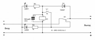
The diagram of a transformerless capacitive power supply is shown in the figure. The values specified for the components depend on the circuit parameters; formulas for calculating these values are given. L and N represent the phase line and zero of the AC mains voltage, respectively, and Vout is the output voltage from the power supply. The output current is designated as Iout.
The inrush current, which can damage power supply components, is limited by resistor R1 and the reactance of capacitor C1. Element D1 is a zener diode, which provides stabilization of the reference voltage, and D2 is a conventional silicon diode, whose task is to rectify alternating voltage. The load voltage remains constant as long as the output current Iout is less than or equal to the input current Iin, the value of which can be calculated as:
Where VZ is the zener diode voltage, VRMS is the rms value of the input AC voltage, and f is its frequency. The minimum value of Iin must correspond to the power consumption of the load, and the maximum value is used to select the appropriate power rating for each element. The output voltage Vout can be calculated as:
Where VD is the forward bias voltage D2 is the voltage drop across the diode (usually 0.7 V for a silicon diode). Regarding R1, it is recommended to select an element with a power at least 2 times the value of the theoretical power dissipated by R1 (PR1), which is determined by the formula:
Capacitor C1, from which this type of circuit gets its name, should be selected with a voltage of at least 2 times the AC mains voltage (400 V minimum). Diode D1 must have a power of at least 2 times the theoretical value, determined by the following formula:
The same applies to the power of diode D2, where instead of VZ a constant voltage drop can now be used, such as 0.7V for a typical silicon rectifier diode. In the case of C2, an electrolytic capacitor with a voltage of 2 times the voltage VZ is usually used.
The main advantages of a capacitive solution over a transformer-based power supply are reduced size, weight and cost. Compared to a resistive type block, this circuit provides higher efficiency. The disadvantage is the lack of galvanic isolation of the output voltage from the mains and the higher cost than the resistance limit.
Experiment
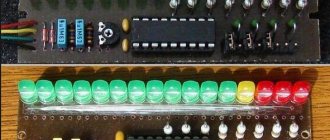
In our experiment, we used resistors with a higher value than indicated in the calculations. A 300 ohm resistor (12V/300 ohms = 40mA) was used as a load resistor to test the load capacity of the power supply.
Output voltage = Vz - Vd = 12 - 0.7 = 11.3 V
Attention. Caution should be used when testing or using this circuit! Do not touch any points on the circuit, as some points on this circuit are live!
Source
Resistive transformerless power supply
The circuit diagram of a typical transformerless resistive power supply is shown in the figure.
Again, the output voltage Vout remains constant as long as the current Iout is less than or equal to the input current Iin, the only difference being that the inrush current limiting is now implemented only by resistor R1. The output voltage Vout can be calculated using the same formula as for a capacitive power supply, and the input current Iin using the following formula:
As in the previous case, components must be selected with a power value at least twice the theoretical value that can be calculated by Ohm's law (P = R x I^2 for R1 and P = V x I for diodes D1 and D2) . Electrolytic capacitor C2 should be selected as for capacitive design.
The advantage of a resistive power supply is that it is smaller in size and weight compared to a transformer circuit and is the cheapest power supply solution. But even in this case there is no galvanic isolation from the AC network, and in addition, the efficiency is lower than in a capacitive solution.
Safety of transformerless power supplies
Both circuits have their limitations: they lack any insulation or protection from mains voltage, which is a serious safety concern. But with minor changes, both presented schemes can be adapted for real-life use and ensure compliance with minimum safety standards. Modifications include:
- Adding a fuse to protect against excessive input current;
- Adding a varistor for transient protection;
- Resistor R2 (R3) is connected in parallel with C1 (C3) to improve electromagnetic immunity;
- Dividing R1 into two resistors R1 and R2 to provide better surge protection and prevent arcing for the resistive circuit.
For small loads, it is possible to reduce the voltage from 220 VAC to a few volts (such as 5, 9, 12 or 24) using only a current limiting resistor, as shown in the circuit diagram. The efficiency of such a circuit is extremely low (1%) since most of the energy is lost as heat through resistor R1. This component really has to do a lot of work to reduce the voltage from 220V to 12V.
In this example, this linear element dissipates an average of 22 Watts. Therefore, it must be rated at least 50 watts. Its dissipation power can be determined by the formula:
Transient voltages (per second) with the values of the components used are shown in the graphs.
The graph above shows how long it takes for the output voltage to reach 12 V. This time depends on the circuit time constant determined by capacitor C1. Here the capacitor charging time is as follows:
- C1 = 100 µF, T = 25 ms
- C1 = 470 µF, T = 130 ms
- C1 = 1000 µF, T = 290 ms
- C1 = 4700 µF, T = 1.4 sec
- C1 = 10000 µF, T = 3 sec
With a constant load resistance, the output voltage ripple depends on the capacitance of capacitor C1. The larger the capacitor capacity, the less ripple the output voltage. When using the above capacitors, the ripple level, measured as the peak-to-peak voltage of the signal, is as follows:
- C1 = 100 µF, ripple = 1.2 Vpp
- C1 = 470 µF, ripple = 261.7 mVpp
- C1 = 1000 µF, ripple = 121.5 mVpp
- C1 = 4700 µF, ripple = 25.3 mVpp
- C1 = 10,000 µF, ripple = 11.9 mVpp
But more important than the ripple, the figure shows that the output voltage from the power supply does not reach the desired voltage of 12 V, but only about 11.3 V.
It turns out that even without a load when connected, the output voltage is always below 12 V. This voltage drop is caused by diode D2. A Schottky diode placed here could reduce it, but not to zero.
LED strip power supply repair
Many power supplies designed for medium and high power (30 W or more) are built on an integrated driver with a built-in power switch, such as KA5l0365, FSDH065RN, etc. Such solutions are also used in household appliances, for example, in power supplies for DVD players. Such microcircuits are interchangeable; you just need to determine the pinout of the burnt chip and install the one you managed to find.
To repair the power supply for a 12V LED strip (and not only), the circuit remains almost unchanged. You need to make a connection similar to what is shown below. Of course, taking into account the pinout.
More complex and reliable blocks are built on PWM controllers:
- TL494;
- KIA494AP;
- MB3759;
- KA7500;
They are similar, below is a power supply diagram for an LED strip using them:
The PWM controller is located at the bottom of the circuit; adjustment is made using P1 (on the right in the diagram). By selecting its value, you can achieve the desired output voltage, somewhat similar to adjusting the 431 stabilizer.
Even if your unit does not have a potentiometer or trimmer, you can install it yourself by replacing the constant one, similar to the diagram I provided.
When repairing, look at the signal at the PWM output, power switches T12 and T13 connected to pins 8 and 11 of the TL494.
The picture below shows the adjustment more clearly; the potentiometer is connected to pin 1 of the IC.
Thus, you can experimentally make power for an LED strip with your own hands from any power supply on a 494 PWM controller.
Almost all power supplies can be reconfigured with your own hands within narrow limits to the required supply voltage for the LED strip. At the same time, you will get by with minimal costs.
Somehow recently I came across a circuit on the Internet for a very simple power supply with the ability to adjust the voltage. The voltage could be adjusted from 1 Volt to 36 Volt, depending on the output voltage on the secondary winding of the transformer.
Take a close look at the LM317T in the circuit itself! The third leg (3) of the microcircuit is connected to capacitor C1, that is, the third leg is INPUT, and the second leg (2) is connected to capacitor C2 and a 200 Ohm resistor and is an OUTPUT.
Using a transformer, from a mains voltage of 220 Volts we get 25 Volts, no more. Less is possible, no more. Then we straighten the whole thing with a diode bridge and smooth out the ripples using capacitor C1. All this is described in detail in the article on how to obtain constant voltage from alternating voltage. And here is our most important trump card in the power supply - this is a highly stable voltage regulator chip LM317T. At the time of writing, the price of this chip was around 14 rubles. Even cheaper than a loaf of white bread.
Description of the chip
LM317T is a voltage regulator. If the transformer produces up to 27-28 volts on the secondary winding, then we can easily regulate the voltage from 1.2 to 37 volts, but I would not raise the bar to more than 25 volts at the transformer output.
The microcircuit can be executed in the TO-220 package:
or in D2 Pack housing
It can pass a maximum current of 1.5 Amps, which is enough to power your electronic gadgets without voltage drop. That is, we can output a voltage of 36 Volts with a current load of up to 1.5 Amps, and at the same time our microcircuit will still output 36 Volts - this, of course, is ideal. In reality, fractions of volts will drop, which is not very critical. With a large current in the load, it is more advisable to install this microcircuit on a radiator.
In order to assemble the circuit, we also need a variable resistor of 6.8 Kilo-Ohms, or even 10 Kilo-Ohms, as well as a constant resistor of 200 Ohms, preferably from 1 Watt. Well, we put a 100 µF capacitor at the output. Absolutely simple scheme!
Assembly in hardware
Previously, I had a very bad power supply with transistors. I thought, why not remake it? Here is the result ;-)
Here we see the imported GBU606 diode bridge. It is designed for a current of up to 6 Amps, which is more than enough for our power supply, since it will deliver a maximum of 1.5 Amps to the load. I installed the LM on the radiator using KPT-8 paste to improve heat transfer. Well, everything else, I think, is familiar to you.
And here is an antediluvian transformer that gives me a voltage of 12 volts on the secondary winding.
We carefully pack all this into the case and remove the wires.
So what do you think?
The minimum voltage I got was 1.25 Volts, and the maximum was 15 Volts.
I set any voltage, in this case the most common are 12 Volts and 5 Volts
Everything works great!
This power supply is very convenient for adjusting the speed of a mini drill, which is used for drilling circuit boards.
A capacitor improves the situation
As you can see in the diagram, adding a polyester capacitor in series with the power line improves efficiency. In this configuration, the efficiency is already up to 20%.
Since the maximum voltage across the capacitor is greater than 320V, it is necessary to select a component that can operate at a voltage of at least 600V, as shown in the figure.
In this configuration, the R1 only dissipates 0.5W, but it is always better to use it with a power rating of at least 2W. Capacitor C2 acts as a resistor and has some capacitance at 50 Hz. More specifically, the capacitance of the capacitor at frequency f is determined by the following formula:
From the above formula, capacitor C2 has a reactance of 6772 ohms at 50 Hz, but, unlike a resistor, it does not generate heat. The output voltage of the circuit is also 12 V minus the voltage drop across diode D1.
What can 12 or 24 volt voltage be used for in everyday life?
In domestic environments, low voltage power supplies are often used. Portable/stationary electrical and electronic devices, as well as some lighting devices, are powered from 12 or 24V DC voltage:
- cordless electric drills, screwdrivers and electric saws;
- stationary pumps for watering gardens;
- audio-video equipment and radio-electronic equipment;
- video surveillance and alarm systems;
- battery-powered radios and players;
- laptops (netbooks) and tablets;
- halogen and LED lamps, LED strips;
- portable ultraviolet irradiators and portable medical equipment;
- soldering stations and electric soldering irons;
- chargers for mobile phones and power banks;
- low-current power supply networks in places with high humidity and landscape lighting systems;
- children's toys, Christmas tree garlands, aquarium pumps;
- various homemade radio-electronic devices, including those based on the popular Arduino platform.
Most devices run on batteries and Li-ion batteries, but the use of commodity items is not always justified in terms of operating costs. Batteries can be charged 300–1500 times, but galvanic cells with high energy capacity and low self-discharge current are expensive. It will be noticeably cheaper to purchase batteries, especially salt and alkaline ones, but such elements will have to be changed frequently. Moreover, to provide a supply voltage of 12 V, you will need 8 series-connected AA or AAA batteries or 1.5-volt “tablets” in a 27A housing.
Therefore, in places with access to a 220 V 50 Hz household network, it is more rational to use a power supply to power electrical receivers with an amperage of more than 0.1 A.
Source
Recommendations for power supply design
When the circuit is disconnected, capacitor C2 can remain charged for a long time. It is recommended to connect a high resistance resistor in parallel with this element, as shown in the figure. This resistor, for example with a resistance of 470 kOhm, does not affect the normal operation of the circuit. Under standard conditions, it dissipates about 100 mW of heat. The complete discharge of capacitor C2 occurs in approximately 1 second, but after 0.4 seconds the voltage value on this element will become non-hazardous to humans.
It should be noted that R2 must be designed to operate at such a high voltage. Therefore, it is common to use two or more regular 1/4 W resistors in series (to increase the maximum breakdown voltage).
As for a series resistor with a current-limiting capacitor, the resistor cannot be completely replaced with a jumper, because when connecting the power supply to the network, you can catch the top of the sine wave and the reactance of the capacitor will be on the order of units of ohms rather than kiloohms. The resistor is a protection against such “luck”. In turn, a large resistor means large power losses and even lower efficiency.
Here is a relatively powerful power supply made for a current of 150 mA 24 V. In addition to current limiting elements and a discharge resistor (C 2.5 uF, R 51R and 1M), the board has a diode bridge, a 24 V zener diode and a 100 uF filter capacitor.
In general, the greatest advantages of a transformerless power supply can be seen when current requirements are up to 30 mA, then of course the weight, number of elements, ease of operation will make the choice of such a circuit a reasonable choice. But always remember about the lack of galvanic isolation from the 220 V network!
Power supply forum
Many novice radio amateurs find it difficult to determine the type of power supply, but it’s not that difficult. The main methods of voltage conversion are to use one of two circuit design options:
- Transformer;
- Transformerless power supplies.
In turn, transformer ones differ according to the type of circuit:
- Network, with a transformer operating at a frequency of 50 Hz;
- Pulse, with a transformer operating at high frequencies (tens of thousands of Hz).
Switching power supply circuits make it possible to increase the overall efficiency of the final product by avoiding static losses on linear stabilizers and other elements.
Transformerless circuits
If there is a need for power from a 220 V household power supply, the simplest devices can be turned on from power supplies that use ballast elements to reduce the voltage. A well-known example of such a power supply is the ballast capacitor circuit.
However, there are a number of drivers with a built-in PWM controller and a power switch for building a transformerless switching step-down converter, these are very often found in LED light bulbs and other equipment.
In the case of power supply from a direct current source, for example, batteries or other galvanic batteries, use:
- Linear voltage stabilizer (integrated stabilizer type KREN or L78xx with or without pass transistor, parametric stabilizer of zener diode and transistor)
- Pulse converter (buck - BUCK, boost - BOOST, or buck-boost - BUCK-BOOST)
The advantages of transformerless power supplies and converters are as follows:
- There is no need to wind the transformer, the transformation is carried out by the inductor and keys;
- A consequence of the previous is the small dimensions of the power supplies.
Flaws:
- The absence of galvanic isolation, in case of malfunctions of the keys, leads to the appearance of voltage from the primary power source. This is critical especially if it is played by a 220 V network;
- Danger of electric shock due to galvanic coupling;
- The large dimensions of the inductor on high-power converters call into question the feasibility of using this power supply topology. With comparable weight and size parameters, it is possible to use a transformer, galvanically isolated converter.
Main types of pulse voltage converters
In the domestic literature, the abbreviation “IPPN” is often found, which stands for: Pulse Buck (or Buck, or both) Voltage Converter
As a basis, three basic schemes can be distinguished.
1. IPPN1 – Step-down converter, in English literature – BUCK DC CONVERTER or Step-down.
2. IPPN2 – Boost converter, in English literature – BOOST DC CONVERTER or Step-up.
3. IPPN3 – Inverting converter with the ability to both increase and decrease voltage, BUCK-BOOST DC CONVERTER.
How does a switching buck converter work?
Let's start by considering the operating principle of the first scheme - IPPN1 .
In the circuit, two supply circuits can be distinguished:
1. “+” from the power source is supplied through a private switch (a transistor of any type of appropriate conductivity) to Lн (storage inductor), then the current flows through the load to the “–” power source.
2. The second circuit is formed from diode D, inductor Ln and connected load Rn.
When the switch is closed, current flows through the first circuit, current flows through the inductor, and energy accumulates in its magnetic field. When we turn off (open) the switch, the energy stored in the coil is dissipated into the load, while current flows through the second circuit.
The voltage at the output (load) of such a converter is equal to
Uout=Uin*Ku
Ku is the conversion coefficient, which depends on the duty cycle of the control pulses of the power switch.
Ku=Uout/Uin
Duty factor “D” is the ratio of the time when the key is open to the PWM period. "D" can take values from 0 to 1.
IMPORTANT: For IPPN1 Ku=D. This means that the control limits of this stabilizer are approximately equal to 0...Uout.
The voltage at the output of such a converter is similar in polarity to the voltage at the input.
How does a switching boost voltage converter work?
IPPN2 - is capable of increasing the voltage from the supply voltage to a value tens of times higher. Schematically, it consists of the same elements as the previous one.
Any converter of this type has three main operating components :
- Controlled switch (bipolar, field-effect, IGBT, MOSFET transistors);
- Uncontrolled switch (rectifier diode);
- Cumulative inductance.
Current always flows through inductance, only its magnitude changes.
In order to understand the principle of operation of this converter, you need to remember the switching law for an inductor: “The current through an inductor cannot change instantly.”
This is caused by a phenomenon called self-induced emf or counter-emf. Since the electromagnetic field of inductance prevents sudden changes in current, the coil can be thought of as a power source. Then in this circuit, when the key is closed, a large current begins to flow through the coil, but, as already mentioned, it cannot increase sharply.
Back-EMF is a phenomenon when an EMF appears at the ends of the coil opposite to that which is applied. If you present this on a diagram for clarity, you will have to imagine the inductor as an EMF source.
The number “1” indicates the state of the circuit when the key is closed. Please note that the power source and the symbol of the EMF coil are connected by positive terminals in series, i.e. their EMF values are subtracted. In this case, inductance prevents the passage of electric current, or rather slows down its growth. As it grows, after a certain time constant interval, the value of the back-EMF decreases, and the current through the inductance increases.
Lyrical digression:
The magnitude of self-induced emf, like any other emf, is measured in Volts.
During this period of time, the main current flows through the circuit: power source-inductance-closed switch.
When the switch SA opens, circuit 2. Current begins to flow along the following circuit: power source-inductance-diode-load. Since the load resistance is often much greater than the channel resistance of a closed transistor. In this case, again, the current flowing through the inductance cannot change abruptly, the inductance always strives to maintain the direction and magnitude of the current, so the back-EMF arises again, but in reverse polarity.
Pay attention to how the poles of the Power Source and the EMF source replacing the coil are connected in the second diagram. They are connected in series with opposite poles, and the magnitudes of these EMFs add up.
This results in an increase in voltage.
During the inductive energy storage process, the load is supplied with energy that was previously stored in the smoothing capacitor.
The conversion factor in IPPN2 is equal to
Ku=1/(1-D)
As can be seen from the formula, the larger D is the duty cycle, the greater the output voltage. The polarity of the output power coincides with the input for this type of converter.
How does an inverting voltage converter work?
The inverting voltage converter is a rather interesting device, because it can operate both in voltage reduction mode and in voltage increase mode. However, it is worth considering that the polarity of its output voltage is opposite to the input, i.e. positive potential appears on the common wire.
Inversion is also noticeable in the direction in which diode D is turned on. The principle of operation is a little similar to IPPN2. While switch T is closed, the process of accumulating inductive energy occurs, power from the source does not reach the load due to diode D. When the switch is closed, inductive energy begins to dissipate in the load.
The current continues to flow through the inductance, a self-inductive emf appears, directed in such a way that a polarity opposite to the primary power source is formed at the ends of the coil. Those. A negative potential is formed at the junction of the transistor emitter (drain, if the transistor is field-effect), the cathode of the diode and the end of the coil winding. At the opposite end, respectively, positive.
The conversion coefficient of IPPN3 is equal to:
Ku=D/(1-D)
By simply substituting the duty cycle into the formula, we will determine that up to a D value of 0.5, this converter acts as a step-down converter, and above that it acts as a step-up converter.
How to control such converters?
It would take forever to describe all the options for constructing PWM controllers; several volumes of technical literature could be written about this. I would like to limit myself to listing a few simple options:
1. Assemble an asymmetrical multivibrator circuit. Instead of VT3, a transistor is connected in IPPN circuits.
2. A slightly more complex option, but more stable in terms of frequency, is PWM on the NE555 (click on the picture to enlarge).
Make changes to the diagram, VT1 is a transistor, change the diagram so that in its place there is an IPPN transistor.
3. The option is to use a microcontroller, so you can also do many additional functions; AVR microcontrollers are well suited for beginners. There is a great video tutorial about this.
conclusions
Switching voltage converters are a very important topic in the power supply industry for electronic equipment. Such circuits are used everywhere, and, recently, with the growth of “homemade” or as it is now fashionable to call “DIY” people and the popularity of the aliexpress website, such converters have become especially popular and in demand, you can order a ready-made board of a converter that has already become a classic LM2596 and similar ones for just a couple of dollars, and you get the ability to adjust voltage or current, or both.
Another popular board is the mini-360
You may notice that these circuits are missing a transistor. The fact is that it is built into the microcircuit; in addition to it, there is a PWM controller, feedback circuits for stabilizing the output voltage, and more. However, these circuits can be enhanced by installing an additional transistor.
If you are interested in designing a circuit to suit your needs, then you can familiarize yourself with the design relationships in more detail in the following literature:
- “Components for building power supplies”, Mikhail Baburin, Alexey Pavlenko, Group
- “Stabilized transistor converters” V.S. Moin, Energoatomizdat, M. 1986.
Earlier, ElectroVesti wrote that the Nobel Prize in Chemistry for 2022 was awarded to John Goodenough, Stanley Whittingham and Akira Yoshino for the development of lithium-ion batteries. The Swedish Academy of Sciences announced this on Wednesday afternoon.
Based on materials from: electrik.info.