Field effect transistor - what is it
It includes three main elements - source, gate and drain. To create them, n-type and p-type semiconductors are used. They can be combined in one of the following ways:
- The drain and source are n-type and the gate are p-type. They are called npn type transistors.
- Those that use pnp polarity. The type of conductivity of each part of the transistor has been changed to the opposite in comparison with the previous version.
Checking with a multimeter
If this part is connected to a power source, then there will be no current. But everything will be different if this is done between the source and the gate or the drain and the gate. It is necessary that a voltage be applied to the gate corresponding in sign to its conductivity type (positive for p-type, negative for n-type). Then current will flow through this part. The higher the voltage applied to the gate, the stronger it will be.
The difference between a field-effect transistor and a bipolar transistor
The transistor will become open provided that a potential difference of the required polarity is applied to the gate. In this case, with the help of an electric field, a channel is created between the source and drain, through which electric charges can move. Other types of transistors control based on current rather than voltage.
The electronic components in question are also called mosfets. This word comes from the abbreviation MOSFET - Metal Oxide Semiconductor Field Effect Transistor (translated this means: metal-oxide-semiconductor field-effect transistor).
Varieties of field beetles
How to test a transistor? 2 easy ways
It’s embarrassing to admit, but yesterday we didn’t know how to check the transistor (TRZ). After interviewing seasoned builders, the editors of ThisDom compiled simple step-by-step inspection instructions. And it turns out that there are 2 ways to determine the suitability of a device.
Content:
How to check a transistor and what is it even?
Before installing a new transistor on the board, it is better to first check it for serviceability. Most often, defects come from domestic manufacturers. Radio amateurs may have transistors taken from an old motherboard. Then it is better to immediately check the transistor for functionality than to later look for a faulty part in the circuit.
To check TRZ, use a digital multimeter or a conventional tester.
IMPORTANT! The tester is also called a continuity tester.
Photo 1 - Multimeter used to check TRZ
How does it work
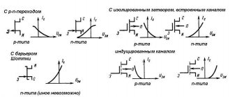
The field-effect transistor differs from other varieties in the features of its device. It can be one of two types:
- with control transition;
- with insulated shutter.
The first of them are n channel and p channel. The first of them are more common. They use the following operating principle.
A semiconductor with n-conductivity is used as a basis. The source and drain contacts are connected to it on opposite sides. In the middle part, on opposite sides, there are inclusions of a conductor with p-conductivity - they are a gate. The part of the semiconductor that is between them is a channel.
You might be interested in Soldering hair dryer
Transistor with control junction
If a potential difference is applied to the source and drain of an n channel transistor, then current will flow. However, when a negative voltage is applied to the gate relative to the source, the channel width for electron movement will decrease. As a result, the current strength will become less.
Thus, by decreasing or increasing the width of the channel, it is possible to regulate the current strength between the source and drain or isolate them from each other.
In p-channel transistors, the operating principle will be similar.
This type of FET is becoming less common, and is being replaced by those that use an insulated gate. They can be one of two types: npn or pnp. Their operating principle is similar. The first of them will be discussed here in more detail: npn.
In this case, a p-type semiconductor is used as the basis for the transistor. Two parallel strips of semiconductor with a different type of main charge carriers are built into it. An insulator is laid between them on the surface, and a layer of conductor is installed on top. This part is the gate, and the strips are the source and drain.
Transistor device
When a positive voltage is applied to the gate relative to the source, a positive charge is applied to the plate, creating an electric field. It attracts positive charges to the surface, creating a channel for current to flow between source and drain. The higher the voltage applied to the gate, the higher the current flows between the source and drain.
For all types of field-effect transistors, control occurs by applying voltage to the gate.
Transistor open
Basic types of transistors
There are two main types of transistors - bipolar and field-effect. In the first case, the output current is created with the participation of carriers of both signs (holes and electrons), and in the second case - only one. Testing the transistor with a multimeter will help determine the malfunction of each of them.
Bipolar transistors are essentially semiconductor devices. They are equipped with three pins and two pn junctions. The operating principle of these devices involves the use of positive and negative charges - holes and electrons. Flowing currents are controlled using a specially dedicated control current. These devices are widely used in electronic and radio engineering circuits.
Bipolar transistors consist of three-layer semiconductors of two types - “p-p-p” and “p-p-p”. In addition, the design has two pn junctions. The semiconductor layers are connected to external terminals through non-rectifying semiconductor contacts. The middle layer is considered the base, which is connected to the corresponding pin. Two layers located at the edges are also connected to the outputs - the emitter and collector. In electrical circuits, an arrow is used to indicate the emitter, indicating the direction of current flowing through the transistor.
In different types of transistors, holes and electrons - carriers of electricity - can have their own functions. The most common type is p-p-p due to the best parameters and technical characteristics. The leading role in such devices is played by electrons, which perform the main tasks of ensuring all electrical processes. They are approximately 2-3 times more mobile than holes, and therefore have increased activity. Qualitative improvements in devices also occur due to the collector junction area, which is significantly larger than the emitter junction area.
Each bipolar transistor has two pn junctions. When testing a transistor with a multimeter, this allows you to check the performance of the devices by monitoring the resistance values of the transitions when direct and reverse voltages are connected to them. For normal operation of the p-p-p-device, a positive voltage is applied to the collector, under the influence of which the base junction opens. After the base current occurs, the collector current appears. When a negative voltage occurs in the base, the transistor closes and the current flow stops.
The base junction in pnp devices opens when exposed to negative collector voltage. Positive voltage causes the transistor to turn off. All the necessary collector characteristics at the output can be obtained by smoothly changing the current and voltage values. This allows you to effectively test the bipolar transistor with a tester.
There are electronic devices in which all processes are controlled by the action of an electric field directed perpendicular to the current. These devices are called field-effect or unipolar transistors. The main elements are three contacts - source, drain and gate. The design of the field-effect transistor is complemented by a conductive layer that acts as a channel through which electric current flows.
These devices are represented by modifications of the “p” or “p”-channel type. Channels can be located vertically or horizontally, and their configuration can be volumetric or near-surface. The latter option is also divided into inversion layers containing enriched and depleted ones. The formation of all channels occurs under the influence of an external electric field. Devices with near-surface channels have a metal-dielectric-semiconductor structure, which is why they are called MOS transistors.
What malfunctions occur
Field-effect transistors can be overloaded with current during testing and, as a result of overheating, become faulty.
Important! They are vulnerable to static voltage. During the work, you need to ensure that it does not fall on the part being tested.
When working as part of a circuit, a breakdown may occur, as a result of which the field-effect transistor becomes faulty and must be replaced. It can be detected by the low resistance of pn junctions in both directions.
You can determine how efficient a transistor is by testing it with a digital multimeter.
Pin assignment
This should be done as follows (for example, the widely used M-831 model is used, a field-effect transistor with an n-type channel is considered):
- The multimeter must be switched to diode test mode. It is marked on the panel with a schematic diagram of a diode.
- Two probes are attached to the device: black and red. There are three slots on the front panel. Black is set to the bottom, red to the middle. The first of them corresponds to the negative pole, the second to the positive pole.
- It is necessary to determine on the field-effect transistor being tested which outputs correspond to the source, gate and drain.
- Some models additionally have an internal diode that protects the part from overload. First you need to check how it works. To do this, the red wire is connected to the source, and the black wire to the drain.
This may interest you. What is the formula for finding the resistance of a conductor?
Checking the diode in the forward direction
A value within the range of 0.5-0.7 should appear on the indicator. If the wires are swapped, the screen will indicate one, which means that no current flows in that direction.
Diode test in reverse direction
- Next, the functionality of the transistor is checked.
If you connect the probes to the source and drain, then the current will not pass through them. To open the shutter. A positive voltage must be applied to the gate. It must be taken into account that a positive potential is applied to the red probe from the multimeter. Now it is enough to connect it to the gate, and the black one to the drain or source, so that the transistor begins to pass current.
Channel opening
Now, if the red wire is connected to the source, and the black wire to the drain, then the multimeter will show a certain voltage drop value, for example, 60. If you connect it the other way around, the indicator will be approximately the same.
If a negative potential is applied to the gate, this will turn off the transistor in both directions, but the built-in diode will work. If the field switch does not close, this indicates its malfunction.
Checking the p-channel mofset is done in a similar way. The difference is that when testing where previously a red probe was used, a black one is now used and vice versa.
Operation of a field-effect MOS transistor
How to ring a mosfet with a multimeter
In the life of every home craftsman who knows how to hold a soldering iron and use a multimeter, there comes a time when some complex electronic equipment breaks down and he is faced with a choice: send it to a service center for repairs or try to repair it himself. In this article we will look at techniques that can help him with this.
So, your equipment is broken, for example an LCD TV, where should you start repairing it? All craftsmen know that it is necessary to begin repairs not with measurements, or even immediately resolder the part that aroused suspicion of something, but with an external inspection. This includes not only inspecting the appearance of the TV circuit boards, removing its cover, looking for burnt radio components, and listening to hear a high-frequency squeak or click.
We connect the device to the network
To begin with, you just need to turn on the TV to the network and see: how it behaves after turning it on, whether it responds to the power button, or the standby mode LED is blinking, or the image appears for a few seconds and disappears, or there is an image but there is no sound, or vice versa. Based on all these signs, you can obtain information from which you can build upon for further repairs. For example, by blinking an LED at a certain frequency, you can set a fault code, self-testing of the TV.
TV error codes by LED blinking
After the signs have been established, you should look for a schematic diagram of the device, or better yet, if a Service manual for the device has been issued, documentation with a diagram and a list of parts, on special websites dedicated to electronics repair. It will also not be amiss in the future to enter the full name of the model into a search engine, with a brief description of the breakdown, conveying its meaning in a few words.
True, sometimes it is better to search for a diagram by the device chassis, or the name of the board, for example a TV power supply. But what if you still couldn’t find the circuit, and you are not familiar with the circuitry of this device?
Block diagram of LCD TV
In this case, you can try to ask for help on specialized forums for repairing equipment, after conducting preliminary diagnostics yourself, in order to collect information from which the technicians helping you can build on. What stages does this preliminary diagnosis include? First, you must make sure that power is supplied to the board if the device does not show any signs of life at all. This may seem trivial, but it wouldn’t hurt to test the power cord for integrity using the audio test mode. Read here how to use a regular multimeter.
Tester in audio mode
Then the fuse is tested in the same multimeter mode. If everything is fine here, we should measure the voltage at the power connectors going to the TV control board. Typically, the supply voltages present on the connector pins are labeled next to the connector on the board.
TV control board power connector
So, we measured and there is no voltage at the connector - this indicates that the circuit is not functioning correctly, and we need to look for the reason for this. The most common cause of breakdowns found in LCD TVs are banal electrolytic capacitors, with high ESR, equivalent series resistance. Read more about ESR here.
Capacitor ESR Table
At the beginning of the article, I wrote about a squeak that you may hear, and so its manifestation, in particular, is a consequence of the overestimated ESR of small-value capacitors located in the standby voltage circuits. To identify such capacitors, you need a special device, an ESR meter, or a transistor tester, although in the latter case, the capacitors will have to be unsoldered for measurement. I posted a photo of my ESR meter that allows me to measure this parameter without soldering below.
My ESR meter
What to do if such devices are not available, and suspicion falls on these capacitors? Then you will need to consult on repair forums and clarify in which node, which part of the board, the capacitors should be replaced with ones that are known to work, and only new (!) capacitors from a radio store can be considered as such, because used ones have this parameter, ESR may also be off the charts or already on the verge.
Photo - swollen capacitor
The fact that you could remove them from a device that previously worked does not matter in this case, since this parameter is important only for working in high-frequency circuits; accordingly, earlier, in low-frequency circuits, in another device, this capacitor could function perfectly, but have an ESR parameter that is very high. The work is greatly facilitated by the fact that high-value capacitors have a notch in their upper part, along which, if they become unusable, they are simply opened, or a swelling forms, a characteristic sign of their unsuitability for anyone, even a novice master.
Multimeter in Ohmmeter mode
If you see blackened resistors, you will need to test them with a multimeter in ohmmeter mode. First, you should select the 2 MOhm mode; if there are values on the screen that differ from unity, or the measurement limit is exceeded, we should accordingly reduce the measurement limit on the multimeter to establish its more accurate value. If there is one on the screen, then most likely such a resistor is broken and should be replaced.
Color coding of resistors
If it is possible to read its denomination by marking it with colored rings applied to its body, it’s good, otherwise you can’t do without a diagram. If the circuit is available, then you need to look at its designation and set its rating and power. If the resistor is precision, its (precise) value can be set by connecting two ordinary resistors in series, a larger and a smaller value, the first we set the value roughly, the last we adjust the accuracy, and their total resistance will add up.
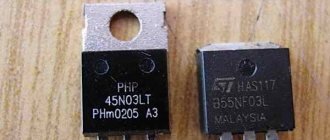
Transistors are different in the photo
Transistors, diodes and microcircuits: it is not always possible to determine a malfunction with them by appearance. You will need to measure with a multimeter in audio testing mode. If the resistance of any of the legs, relative to some other leg, of one device, is zero, or close to it, in the range from zero to 20-30 Ohms, most likely such a part must be replaced. If this is a bipolar transistor, you need to call its pn junctions in accordance with the pinout.
Checking the transistor with a multimeter
Most often, such a check is enough to consider the transistor to be working. A better method is described here. For diodes, we also cause a pn junction, in the forward direction, there should be numbers of the order of 500-700 when measured, in the reverse direction one. The exception is Schottky diodes, they have a lower voltage drop, and when calling in the forward direction, the screen will show numbers in the range of 150-200, and in the reverse direction it will also be one. Mosfets and field-effect transistors cannot be checked with a conventional multimeter without soldering; you often have to consider them conditionally working if their terminals do not short-circuit with each other, or have low resistance.
Mosfet in SMD and regular housing
It should be taken into account that mosfets have a built-in diode between the Drain and the Source, and when dialing, the readings will be 600-1600. But there is one nuance here: if, for example, you ring the mosfets on the motherboard and hear a beep at the first touch, do not rush to write the mosfets into the broken one. Its circuits contain electrolytic filter capacitors, which, when charging begins, are known to behave for some time as if the circuit were short-circuited.
Mosfets on PC motherboard
This is what our multimeter shows, in audible dialing mode, with a squeak for the first 2-3 seconds, and then increasing numbers will appear on the screen, and the unit will be set as the capacitors charge. By the way, for the same reason, in order to save the diodes of the diode bridge, a thermistor is installed in switching power supplies that limits the charging currents of electrolytic capacitors at the moment of switching on, through the diode bridge.
Diode assemblies on the diagram
Many novice repairmen I know who seek remote advice on VKontakte are shocked - you tell them to ring the diode, they ring it and immediately say: it’s broken. Here, as a standard, an explanation always begins that you need to either lift, unsolder one leg of the diode, and repeat the measurement, or analyze the circuit and board for the presence of parallel-connected parts in low resistance. These are often the secondary windings of a pulse transformer, which are connected parallel to the terminals of the diode assembly, or in other words, a dual diode.
Parallel and series connection of resistors
Here it is best to remember once, the rule of such connections:
- When two or more parts are connected in series, their total resistance will be greater than the greater resistance of each individually.
- And with a parallel connection, the resistance will be less than the smaller of each part. Accordingly, our transformer winding, which has a resistance of 20-30 Ohms at best, by shunting, imitates for us a “broken” diode assembly.
Of course, unfortunately, it is impossible to reveal all the nuances of repairs in one article. For preliminary diagnosis of most breakdowns, as it turned out, a conventional multimeter used in the voltmeter, ohmmeter, and audio test modes is sufficient. Often, if you have experience, in the event of a simple breakdown and subsequent replacement of parts, the repair is completed, even without a diagram, carried out by the so-called “scientific poking method”. Which, of course, is not entirely correct, but as practice shows, it works, and, fortunately, not at all as shown in the picture above). Happy repairs to everyone, especially for the Radio Circuits website - AKV.
Instructions for dialing without soldering
To check whether the field-effect transistor is working, you need to unsolder it and test it with a multimeter. However, situations may arise when you need several such parts in the circuit and it is not known which of them are working and which are not. In this case, it is useful to know how to test a field-effect transistor with a multimeter without desoldering.
Digital multimeter
In this case, a test without desoldering is used. It gives an approximate result.
Important! After the presumably faulty element has been identified, it is disconnected and checked, obtaining accurate information about its performance. If it functions normally, it is installed in its original place.
Testing without desoldering is performed as follows:
- Before testing the field-effect transistor with a digital multimeter, disconnect the device from the electrical outlet or from the batteries. The latter are removed from the device.
- If the red probe is connected to the source, and the black probe to the drain, then you can expect that the multimeter will show 500 mV. If you can see this figure or one that exceeds it on the indicator, this indicates that the transistor is fully functional. If this value is much less - 50 or even 5 mV, then in this case a malfunction can be assumed with a high probability.
You might be interested in How to measure voltage
With control pn junction
- If the red multimeter probe is moved to the gate, and the black one is left in the same place, then the indicator will show 1000 mV or more, which indicates the serviceability of the field-effect transistor. When the difference is 50 mV, this raises concerns that the part is damaged.
- If the black probe of the tester is placed on the source, and the red probe is placed on the gate, then for a working transistor you can expect 100 mV or more on the display. In cases where the figure is less than 50 mV, there is a high probability that the part being tested is inoperative.
It must be taken into account that the conclusions obtained without soldering are probabilistic in nature. These data allow us to draw preliminary conclusions about the field-effect transistors used in the circuit.
To check, they need to be unsoldered, checked and installed if the functionality is confirmed.
Preparing for work
Analogs
Full foreign analogues of the device are: STP11NK40Z (STM), D84EQ2 (National Semiconductor). The similar type of case, pinout and characteristics of these devices will not require changes to the project diagram in case of replacement. Also, the most suitable replacement for the domestic analogue of the irf740 is the KP776 series transistors. KP776 is produced by JSC INTEGRAL, Minsk, Republic of Belarus. In his datasheet, the irf740 transistor is listed as a prototype. Here are the maximum permissible electrical operating modes of the KP776:
Safe work rules
Mosfets are very vulnerable to static electricity. In this case, a breakdown may occur. To prevent this from happening, you need to remove it through testing.
When soldering, a situation is possible where the heat entering the transistor will lead to its damage. In this case, it is necessary to provide heat dissipation. To do this, just hold the transistor terminals with pliers during the soldering process.
Field workers are widely used in modern electronic devices. When a breakdown occurs, you need to know how to check the mosfet. It is possible to find out if it is working if you use a multimeter for this.
Device characteristics
To correctly test a thyristor with a multimeter, you need to not only understand the principle of its operation, but also know its main characteristics. The most significant parameter of an element is its current-voltage characteristic (volt-ampere characteristic). It clearly shows the dependence of the current flow through the device on the voltage applied to its terminals. The current-voltage characteristic of the dinistor is S-shaped. This characteristic is divided into six zones:
- Open area. At this gap, the element offers virtually no resistance to the current passing through it. Its conductivity is maximum. This zone ends at a point where current stops flowing.
- Negative resistance area. Provokes the onset of an avalanche breakdown.
- Breakdown of the collector junction. During this interval, the element operates in avalanche breakdown mode, which causes a sharp decrease in the voltage at its terminals.
- Direct connection section. In this area, the dinistor is closed, since the potential difference applied to its terminals is less than that required for a breakdown to occur.
- The fifth and sixth sections describe the operation of the device in the lower half of the current-voltage characteristic and correspond to the states of reverse switching on and breakdown of the element.
Analyzing the current-voltage characteristic, we can conclude that the operation of a dinistor is similar to a diode, but, unlike the latter, to open it it is necessary to apply a voltage several times higher than the diode value. At the same time, the dinistor is characterized by a number of parameters that determine its use in electrical circuits. Its main characteristics include the following values:
- Open potential difference. Usually indicated in relation to the opening current value. Its unit of measurement is the volt.
- The lowest current value in the open state. This value depends on the temperature of the device and decreases as it increases. Measured in milliamps.
- Switching time. It is characterized by the period of time during which the operating mode of the device transitions from one stable state to another. This value is in microseconds.
- Locked state current. Determined by the reverse voltage value and rarely exceeds 500 µA.
- Capacity. This parameter characterizes the generalized parasitic capacitance that occurs in the element. Because of it, the use of the device in high-frequency circuits is limited and the speed of switching operating modes is reduced. It is measured in picofarads.
- Holding current. Indicates the value at which the dinistor is open. The unit of measurement is ampere.
Transistor testing method
To check the PNP transistor with a multimeter, touch the base terminal with the negative probe (black), and touch the collector and emitter terminals with the positive probe (red). If the transistor is intact, then the voltage drop in the test mode (testing) in millivolts will be in the range of 500 - 1200 Ohms, and the difference between these values should be small. After this, we swap the probes; the multimeter should not show any drop. Next, we check the collector - emitter in both directions (swap the probes), there should also be no values here.
Checking NPN transistors with a multimeter is identical, with the only difference being that the multimeter should show the voltage drop across the transitions when the positive probe touches the base of the transistor, and the black probe alternately touches the collector and emitter.
Watch a short video of checking a transistor with a multimeter.
At the beginning I mentioned that in some cases, such a check may give a false conclusion. It happens when repairing a TV, when checking a soldered transistor with a multimeter, all transitions show normal values, but it does not work in the circuit. This can only be revealed by replacement.
The compound transistor is checked by inserting it into the holes on the panel of a multimeter or other device. To do this, you need to know what conductivity it is and then insert it, not forgetting to switch the tester to the appropriate position.
You can check the power transistor, as well as the line transistor, using the same method by examining the transitions B-K, B-E, K-E, but since these transistors in most cases have built-in diodes (K-E) and resistances (B-E ) all this must be taken into account. If an element is unfamiliar, it is better to look at its datasheet.
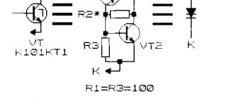
Hand made probe assembly
A homemade device (probe) will immediately determine the serviceability of a transistor of any type. Let us present the simplest effective scheme.
What you will need (only 3 working components):
- in addition 2 elements. The LED is connected to the secondary winding through a resistor. 100 Ohm, its power is not important, as is the polarity of the first element, since a variable value appears at the output.
- base – any small down-trans. (from a switching power supply, from a household light bulb, small household appliances). Our primaries have 24 rounds with a middle tap; secondary – 15;
There is also a slot for inserting parts to be controlled according to the pinout. For bipolar straight wire types (KT 814... 818, etc.) the base passes through a resistor to one of the intermediate contacts, which (coupler) is connected to the "+" power supply. We connect the outlet to the power supply “-”, assembly. – free exit of primary organs. If the conductivity of the part is reversed, simply change the "+" and "-". Likewise with field workers, the main thing is to follow the pinout. If the indicator lights up after turning on the power, the product is working.
The probe is powered by 3.7–6 V; A lead-acid or lithium-ion battery will do.
Methods for checking TRZ
Method No. 1: with direct connection
A simple algorithm for checking any types of TRZ and diodes:
1.Connect the red (plus) probe to the base of the transistor being tested, and the black (minus) probe to the collector terminal.
Photo 4 - Connecting probes
2. The red probe is left in place, and the black one is connected to the emitter terminal.
Photo 5 - The junction conducts current. This method allows you to check the transition when you turn it on directly.
Method No. 2: when turned back on
To make sure it works, it is better to double-check it when connecting it back: the pn junction will not be able to conduct current, and the number 1 should be displayed on the multimeter screen - this will mean that the junction resistance is very high and there is no way to pass current.
To check the transition in reverse inclusion you need:
1. Change the polarity of the probes to the transistor output, that is, connect the negative one to the base, and the positive one to the collector.
Photo 6 - Value 1 on the multimeter: PN junction does not pass current during reverse connection
We tested the TRZ in two ways and made sure it worked.
Transistors are of two types:
- NPN;
- PNP.
The table shows examples of types of transistors that differ in functionality.
| Model | Description |
| Control of the resistance of a current-carrying channel using a transverse electric field. |
| Power | In welding machines and in devices where there are heavy loads. |
| Lowercase | In televisions for generating current in the horizontal scanning system, generating high voltage on an amplifier, kinescope, and powering circuits. |
| Always open when voltage is applied to the gate. |
| Single junction | Equipped with three electrodes and one junction. Used in pulse and measuring instruments. There is a section with negative differential resistance. |
Variety TRZ
| Model | Description |
| Features an insulated shutter. Used in industry and electrical appliances. |
| Used for motors, relays, regulators. |
| Due to the housing, SMD technology (SMD) is used for surface mounting. |
| IRF | High power, isolated shutter. |
| The operating principle is to change the electric field in a semiconductor. |
Comparison table of popular transistor models
| Model | Description |
| Silicic. Low-frequency and high-voltage, used in various power supplies (switching), for mobile gadgets and chargers. |
| Kt315 | Silicon bipolar. Used in various electronic devices. They are inexpensive, but belong to the low-power class. |
| Kt117 | Silicon bipolar. Used in various electronic devices. Cheap. |
| Bu808dfi | Bipolar. Used in TVs and radios. |
| Irf 404 | Bipolar. High power and isolated shutter. Used in welding machines and engines. |
| 13001 | Silicic. Low-frequency and high-voltage, used in various power supplies (switching), for mobile gadgets and chargers. |
| D2499 | Silicon and high voltage. Used in various electronic devices. |
| Kt825 | Silicon bipolar. Used in various electronic devices. It is inexpensive and belongs to the powerful class. |
| D1555 | Silicon and high voltage. Used in various electronic devices. |
| Silicon bipolar transistor. Used in electronic devices. Cheap and powerful. |
| Kt827a | Silicon bipolar. Cheap and powerful. |
| Silicon bipolar. They belong to the powerful class. |
| Tip 122 | Used in circuits with amplifiers and switches. |
| 13007 | Silicic. Low-frequency and high-voltage, used in various power supplies (switching), for mobile gadgets and chargers. |
| Silicic. Low-frequency and high-voltage, used in power supplies (switching), for mobile gadgets and chargers. |
| Bipolar. High power, isolated shutter. Used in welding machines and engines. |
| High current gain. Used in TVs and radios. |
| Needed to control the resistance of the current-carrying channel using a transverse electric field. |
| To control the resistance of a current-carrying channel using a transverse electric field. |
| S2000n | For generating current in horizontal scanning systems and generating high voltage. |