Neodymium magnet is a rare earth metal that is resistant to demagnetization and has the ability to magnetize certain materials. Used in the manufacture of electronic devices (computer hard drives, metal detectors, etc.), medicine and energy.
Neodymium magnets are used in the manufacture of generators operating in various types of installations that generate electric current.
Currently, generators made using neodymium magnets are widely used in the manufacture of wind turbines.
Windmill with axial generator on neodymium magnets
The strongest magnets with optimal parameters for use in generator design are neodymium magnets. They are somewhat more expensive than conventional ones, but they are many times superior and make it possible to create a powerful device in a relatively compact size.
There is no fundamental difference in the design. Neodymium magnets are manufactured in various form factors, allowing you to choose the most convenient option for yourself - thin oblong bars, tablet shape, cylinders, etc. if a metal rotor is used, then it is not necessary to glue the magnets; they themselves are attached to the base with force. All that remains is to fill them with epoxy to protect them from corrosion.
How to make a perpetual motion machine
Homemade generators with neodymium magnets are basically the same type in terms of their operating principle. The standard option is the axial type.
It is based on a car hub with brake discs. Such a base will become reliable and powerful.
When deciding to use it, the hub should be completely disassembled and checked to see if there is enough lubrication, and if necessary, clean off the rust. Then the finished device will be pleasant to paint, and it will take on a “homey”, well-groomed appearance.
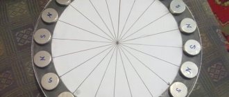
Magnets are glued to the rotor discs. The author of the design presented in the photo in the article took twenty pieces measuring 25*8 millimeters. A different number of poles can be used.
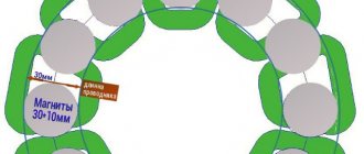
In a single-phase device, the number of poles must be equal to the number of magnets. In three-phase, the ratio of two to three or four to three must be observed. Magnets are placed with alternating poles. They must be precisely located. To do this, you can draw a template on paper, cut it out and accurately transfer it to the disk.
To avoid mixing up the poles, make notes with a marker. To do this, magnets are brought on one side: the one that attracts is designated with a “+” sign, and the one that repels is marked with a “-”. Magnets must attract, that is, those located opposite each other must have different poles.
Usually superglue or something similar is used, and after sticking it is filled with more epoxy resin to increase strength, after making “borders” so that it does not leak out.
Alternating single-phase and three-phase electric current
Electric current is the directed movement of electrically charged particles under the influence of an electric field (Appendix, Fig. 1). Such particles can be: in conductors - electrons, in electrolytes - ions (cations and anions). In the theory of electrical circuits, current is considered to be the directional movement of charge carriers in a conducting medium under the influence of an electric field. Conduction current is the amount of electricity flowing per unit time through the cross section of a conductor:
i=q/t,
where i is current (A), q = 1.6·109 is electron charge (C), t is time (s).
But this expression is valid only for DC circuits. For alternating current circuits, the so-called instantaneous current value is used, equal to the rate of change of charge over time:
i(t)= dq/dt.
An electric current is called alternating if it changes its direction over a certain time and continuously changes in magnitude. The value of alternating current varies according to a sinusoidal law (Appendix, Fig. 2):
i = Im sin (2πft),
Where; i – instantaneous current value, Im – amplitude or maximum current value, f – alternating current frequency value, t – time.
Alternating current is widely used due to the fact that alternating current electricity can be technically simply and economically converted from lower voltage energy to higher voltage energy and vice versa. This property of alternating current allows electricity to be transmitted through wires over long distances.
Industrial alternating electric current is obtained using electric generators, the operating principle of which is based on the law of electromagnetic induction. The rotation of the generator is carried out by some energy source.
Alternating single-phase electric current has the following main characteristics:
f – frequency of alternating current determines the number of cycles or periods per unit of time. The unit of measurement of alternating current frequency is Hertz (Hz) (1Hz = 10-3kHz = 10-6mHz);
Τ – period – time of one complete change of a variable value (if 1 period Τ occurs in 1 second, then frequency f = 1 Hz);
ω – angular velocity equal to – ω=2πf;
The current strength at individual moments when it changes along a sinusoid is called instantaneous current values. The largest instantaneous value of a single-phase alternating current when it changes along a sinusoid is called amplitude. Currently, the three-phase alternating current system is most widespread throughout the world. A three-phase system of electrical circuits is a system consisting of three circuits in which alternating electromotive forces of the same frequency act, shifted in phase relative to each other by 1/3 of the period (φ = 2π/3) (Appendix, Fig. 3) . Each individual circuit of such a system is briefly called its phase, and the system of three phase-shifted alternating currents in such circuits is simply called three-phase current.
Creating a device with your own hands
Obtaining electrical energy in huge quantities without consuming fuel is a tempting and quite feasible idea. The creation of such a device can be considered using the example of the Adams generator. For self-assembly you will need:
- Magnets. The larger the magnet, the more it affects the induction field, as well as the amount of energy generated. For a low-power generator, small pieces are suitable. It is desirable that the sizes be the same. For normal operation, 15 pieces are enough. The positive pole of one magnet must be installed opposite the positive pole of the other. If this condition is not met, then there will be no induction field.
- Copper wires.
- Two coils. You can get them from old engines or wind the wire yourself.
- Sheet steel for making the body.
- Bolts, washers, screws and nails. They are necessary for fastening small elements.
You might be interested in how a voltmeter works, the principle of operation and the purpose of the device
First, the magnet must be secured to the base of the coil. This can be done by drilling a hole in it and then securing it with bolts. The wires on the coils should be 1.25 mm thick and have a layer of insulation. The coils should be mounted on a metal frame so that there are small gaps between the ends. This is required for free rotation of the main element.
At this stage, the device can already be used. It is quite simple to check the correct assembly: you should manually turn the magnets. If the structure is assembled correctly, voltage will arise at the ends of the winding.
This is the most primitive generator, powered by magnets. But based on such a scheme, it is possible to create a device that will be able to provide electricity to the entire house. You can also purchase ready-made devices from trusted manufacturers.
Rotor creation process
The magnets should be positioned taking into account the alternation of poles, and as accurately as possible, but before you start sticking them, you need to either create a paper template or draw lines dividing the disk into sectors. To avoid mixing up the poles, we make marks on the magnets. The main thing is to fulfill the following requirement: those magnets that stand opposite each other must be turned with different poles, that is, attract each other.
The magnets are glued to the disks using super glue and filled in. You also need to make borders along the edges of the disks and in their center, either by wrapping tape or molding them from plasticine to prevent spreading.
Modification of a car generator
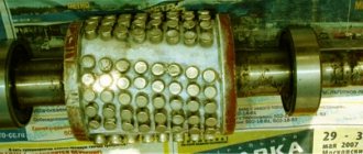
Creating a permanent magnet rotor requires quite a serious intervention in the design. It is necessary to reduce the diameter by the thickness of the magnets plus the thickness of the steel sleeve, which is placed on the rotor to form a continuous magnetic flux and at the same time serves as a landing pad for the magnets. Some experts do without a sleeve, installing magnets directly on the rotor with a reduced diameter and fixing them with epoxy.
The manufacturing process requires the participation of production equipment. The rotor is clamped into the lathe and the layer is carefully removed so that the installed magnets rotate with minimal clearance, but quite freely. The magnets are installed on the rotor plates with alternating polarity.
Making a rotor from a hub and brake disc
The considered method applies to ready-made generators that require minor design changes. Such devices include car generators, which are often used by amateur designers as a basic device. Often, generators are assembled completely independently, without having a ready-made device.
In such cases, they act somewhat differently. The basis is a car hub with a brake disc. It is well-balanced, durable and adapted to certain types of loads. In addition, the size of the hub allows a large number of magnets to be placed around the circumference, allowing three-phase voltage to be obtained.
Magnets with alternating polarity are placed at a distance equidistant from the center. Obviously, the highest number can be set by gluing them as close to the outer edge as possible. The most accurate indicator will be the size of the magnets, which will determine the possibility of placement at a certain distance. The number of magnets must be even so that the rhythm of alternating poles during rotation does not break down.
Gluing magnets to the hub is done using any glue; the best option is epoxy resin, which is used to completely fill the magnets. This protects them from moisture or mechanical stress. Before pouring, it is recommended to make a plasticine rim along the edge of the hub to prevent the epoxy from flowing down from the hub.
The design of the generator on a car hub is most convenient when making a vertical windmill. It is noteworthy that a similar scheme can be used without a hub, on a disk cut from ordinary plywood. This design is much lighter, allows you to choose a convenient size, which makes it possible to create a sensitive and productive device.
Vega device and its features
BTGs operate according to the scheme of capturing free energy, after which it is converted into an induction current. Adams and Bedini devoted their lives to studying this physical phenomenon. The devices can be used as an autonomous power supply for:
- private houses;
- farm or forest land;
- shipping;
- automotive industry;
- aircraft manufacturing and astronautics.
The effectiveness of fuel-free magnetic generators often manifests itself in places that cannot be supplied with fuel, and the strength of natural energy is not enough to fully provide electricity. It should be understood that Adams' device is not an eternal generator of electricity. During operation, it requires periodic repairs. The unit also requires constant maintenance.
You might be interested in everything about phase-zero loops
The fuel-free magnet generator has a number of advantages:
- The device can be used in any weather conditions, as well as away from power supply networks.
- The fuel is kinetic energy.
- There are no restrictions on electricity production.
- Completely safe for the human body and nature.
- You can make a fuel-free generator with your own hands.
- The unit is very compact.
- The minimum service life is 20 years.
The main advantage is that you do not need to move the shaft yourself. The entire process is automated, thanks to the conversion of kinetic energy into electrical impulse.
Electrical and technical parameters of the generator
The voltage is calculated using the formula:
Homemade generator
U=2*Ch*KP*KK*KV*MI*P, where:
- U – voltage in Volts;
- H – frequency of rotation of the generator rotor per second;
- KP – number of magnetic poles;
- КК – number of induction coils in the stator;
- KV – the number of turns of the conductor in one induction coil;
- MI is the magnetic induction in T, which is formed in a standard gap (2 mm);
- P – surface area of one neodymium magnet, in sq. m.
If simple coils are used, a magnetic induction of 0.5 Tesla is taken for calculation. When adding an electrical steel core, the value is increased to 0.7-0.9 T.
For your information. The formula is valid when connecting the windings in a triangle. If a three-phase generator is assembled using a star circuit, the resulting value is multiplied by a correction factor of 1.7.
After calculating the voltage, you need to find out the resistance in the windings. After this, it will be easy to determine the current and power. For a copper conductor, the resistivity is 0.0175 Ohm per mm2/meter. To calculate the total value, use the formula:
C= (US*D)/PP, where:
- C – resistance, in Ohm;
- US – resistivity of a certain material;
- D – conductor length in meters;
- PP – conductor cross-sectional area, mm sq.
To calculate the current, subtract the voltage of the battery connected for charging from the voltage of the magnetic generator at idle. The resulting value is divided by the resistance value calculated using the previous formula.
Increasing/decreasing the speed changes the current accordingly while keeping the voltage at the battery terminals constant. To calculate the performance of a wind turbine in different modes, use the standard formula:
P=I*U, where:
- P – power, Watt;
- I – current strength, Ampere;
- U – voltage, Volt.
Fuel-free generators
Many states are now focusing on the development of alternative energy sources, as well as on saving mineral resources. This is achieved through the use of magnetic electric generators. The principle of their operation lies in the elementary laws of physics. The most successful types of devices are considered to be:
- Fuel-free generator using Adams magnets. Today it is the most popular magnetic motor. It has a fairly simple design, but at the same time a very high efficiency.
- Motor Dudyshev. Its operation is based on a magnetic current, which is modified into an electrical impulse.
- Dudyshev solenoidal motor. Its design includes a magnetic rotor. Shows the greatest efficiency at low power.
- Minato engine. The efficiency of the device is 100%. This is achieved through the use of power amplifiers.
- Johnson motor. This is a fairly popular type of device, but it is not used in industry due to its low power.
Most types of units can be successfully used in various industries. This will not only save on fuel, but also reduce the level of environmental pollution.
Manufacturing the stator of a three-phase alternating current generator
The generator stator is also made of 8 mm thick organic glass plates. In the plates, according to the markings, cavities are milled to accommodate 9 stator winding coils. The coils are wound with insulated copper wire D – 0.35 mm. Each coil holds the number of turns, according to the calculation data given above. The winding coils are glued into the grooves of the stator plates using sealant (Appendix, Fig. 13-15). Winding of all phase coils must be done in the same direction, marking the beginning and end of the winding. The connection of the coils of each phase is made according to the scheme: end - beginning. In total, three phase coils are placed on the stator plates, connected in series (Appendix, Fig. 16). The connection of all phase windings can be made in two ways: star and triangle (Appendix, Fig. 17 - 18). In our case, the connection is made by a star, including all stator plates. Current rectification is carried out by a three-phase rectifier made of semiconductor diodes (N4107) (Appendix, Fig. 18). The entire “sandwich” of the generator is assembled on a base made of organic glass. The stator plates are rigidly attached to the base with metal stands. The rotor plates are movably mounted on a bearing assembly from the disk drive motor. The axis of the bearing assembly passes through the entire generator and fastens the movable rotor plates (Appendix, Fig. 17).
Is it possible to increase the power of a homemade wind generator?
I carefully studied this issue and came to the conclusion that the already assembled axial generator can be upgraded in two ways:
- use additional magnets (stick them on an existing layer);
- install metal cores into the coils (plates from transformers can be used).
It’s worth noting here that initially I wanted to assemble an axial generator according to a completely different scheme. However, due to the lack of a lathe, we had to abandon a more complex option, presented in this video
Manufacturing a rotor for a three-phase alternating current generator
The rotor plates are made of organic glass 5 mm thick. Circles with a diameter of 95 mm were cut out of organic glass; according to the markings, 12 holes were drilled in them for neodymium magnets (D – 15 mm). Magnets with opposite poles were glued into the holes intended for them (Appendix sheet V, Fig. 12 - 13). Three such plates were made for the generator. The central plate, which is located between the stator plates, is made only of organic glass. Metal plates made of steel 1.5 mm thick are glued to the upper and lower rotor plates. Each plate contains 12 magnets, oriented along the poles.
Most popular models
Currently, the most popular generators are models from, U-Polemag, Vega, and Verano-Co. They occupy a large part of the device market.
Vega produces devices that operate on the principle of magnetic induction. This idea was realized by the famous physicist Adams. The price often depends on the power and size of the device. The minimum cost is 45 thousand rubles. This manufacturer has a number of advantages:
- Products from are very environmentally friendly.
- The generators are completely silent, which allows them to be installed anywhere.
- The devices are relatively compact.
- The manufacturer has quite a few models, the power of which starts from 1.5 kW and reaches up to 10 kW.
The minimum service life is 20 years. Batteries must be replaced every 3-4 years.
"Verano-Co" is a Ukrainian manufacturer that uses only high-quality components for its products. It produces generators for both domestic and industrial purposes. The operating principle of the alternative energy source is the same as that of other magnetic units. The cheapest model costs 50 thousand rubles. Prices for devices reach 200 thousand rubles.
You may be interested in How to measure insulation resistance
U-Polemag is a Chinese manufacturer. Represents the largest variety of generator models. The standard efficiency of the devices is 93%. Maximum energy loss is 1%. Often purchased for household use. It has compact dimensions, low noise level and light weight. The package includes cooling systems. The maximum duration of use reaches 15 years. Prices for the model range start from 30 thousand rubles. and reach 90 thousand rubles.
Energizistem produces vertical devices. Consumers do not have a clear opinion about the quality and power of devices. Prices for generators are a little high and start at 50 thousand rubles.
Types of magnets
Permanent magnets are divided into 2 types:
- natural;
- artificial.
Natural
In nature, a natural permanent magnet is a fossil in the form of a fragment of iron ore. Magnetic rock (magnetite) has its own name in every nation. But in each name there is such a concept as “loving”, “attracting metal”. The name Magnitogorsk means the city's location next to mountain deposits of natural magnetite. For many decades, active mining of magnetic ore was carried out here. Today there is nothing left of Magnetic Mountain. This was the development and extraction of natural magnetite.
Until humanity achieved the proper level of scientific and technological progress, natural permanent magnets served for various fun and tricks.
Artificial
Artificial PMs are obtained by inducing an external magnetic field on various metals and their alloys. It was noticed that some materials retain the acquired field for a long time - they are called solid magnets. Materials that quickly lose the properties of permanent magnets are called soft magnets.
In factory production conditions, complex metal alloys are used. The structure of the Magnico alloy includes iron, nickel and cobalt. Alnico alloy contains aluminum instead of iron.
Products made from these alloys interact with powerful electromagnetic fields. As a result, quite powerful PMs are obtained.
Types and forms of PM
Advantages and disadvantages
The advantages of wind generators made using neodymium magnets include the following characteristics:
High efficiency of devices, achieved by minimizing friction losses;
- Long service life;
- No noise or vibration during operation;
- Reduced costs for installation and installation of equipment;
- Autonomy of operation, allowing operation without constant maintenance of the installation;
- Possibility of self-production.
The disadvantages of such devices include:
- Relatively high cost;
- Fragility. Under strong external influence (impact), a neodymium magnet can lose its properties;
- Low corrosion resistance, requiring special coating of neodymium magnets;
- Dependence on operating temperature – when exposed to high temperatures, neodymium magnets lose their properties.
Main characteristics
In order to determine the feasibility of manufacturing a generator using neodymium magnets, you need to consider the main characteristics of this material, which are:
- Magnetic induction B is a strength characteristic of a magnetic field, measured in Tesla.
- Residual magnetic induction Br is the magnetization possessed by a magnetic material when the external magnetic field strength is zero, measured in Tesla.
- Coercive magnetic force Hc - determines the resistance of a magnet to demagnetization, measured in Amperes/meter.
- Magnetic energy (BH)max - characterizes how strong the magnet is.
- Temperature coefficient of residual magnetic induction Tc of Br – determines the dependence of magnetic induction on the ambient temperature, measured as a percentage per degree Celsius.
- Maximum operating temperature Tmax - determines the temperature limit at which the magnet temporarily loses its magnetic properties, measured in degrees Celsius.
- Curie temperature Tcur - determines the temperature limit at which a neodymium magnet is completely demagnetized, measured in degrees Celsius.
The composition of neodymium magnets, in addition to neodymium, includes iron and boron and depending on their percentage, the resulting product, the finished magnet, differs in classes, differing in their characteristics given above. A total of 42 classes of neodymium magnets are produced.
The advantages of neodymium magnets that determine their demand are:
- Neodymium magnets have the highest magnetic parameters Br, Hsv, Hcm, VN.
- Such magnets have a lower cost compared to similar metals containing cobalt.
- They have the ability to operate without loss of magnetic characteristics in the temperature range from – 60 to + 240 degrees Celsius, with a Curie point of +310 degrees.
- From this material it is possible to make magnets of any shape and size (cylinders, disks, rings, balls, rods, cubes, etc.).
Advantages
Devices can be purchased ready-made or made independently. Having purchased a wind generator, all that remains is to install it. All adjustments and alignments have already been completed, tests have been carried out under various climatic conditions.
Neodymium magnets, which are used instead of a gearbox and bearings, allow you to achieve the following results:
- friction is reduced and the service life of all parts is increased;
- vibration and noise of the device during operation disappears;
- the cost decreases;
- energy is saved;
- There is no need to regularly service the device.
A wind generator can be purchased with a built-in inverter that charges the battery, as well as a controller.
Winding method for windmill stator coil
The coils should be wound with thicker wires if possible in order to reduce the resistance in them. This can be done on a mandrel or on a homemade machine.
In order to figure out what power potential the generator has, spin it with one coil, since, depending on how many neodymium magnets are installed and what their thickness is, this indicator may differ significantly. The measurements are carried out without load at the required number of revolutions. For example, if a generator at 200 rpm provides a voltage of 30 V, having a resistance of 3 ohms, then subtract 12 V (battery supply voltage) from 30 V and the resulting result is 18 divided by 3 (resistance in ohms) we get 6 ( current in amperes), which will go from the wind generator to charge the battery. However, as practice shows, due to losses in the wires and diode bridge, the actual indicator that the magnetic axial generator will produce will be less.
The thickness of the stator should be the same as the magnets. The form for it is usually plywood; for strength, fiberglass is placed under the coils and on top of them, and the whole thing is filled with epoxy resin. In order to prevent the resin from sticking to the mold, the latter is lubricated with any fat or adhesive tape is used. The wires are first brought out and fastened together, the ends of each phase are then connected with a triangle or an asterisk.
Stator assembly
To begin with, I had to create a mold from plywood with a lid and bolts in the “ears” of the stator for casting the main part of my homemade product. Then I proceeded according to the following scheme:
- laid fiberglass on the bottom of the mold;
- I treated everything with Vaseline;
- laid out the coils and brought the ends of the wires outside the mold;
- poured epoxy with talc filler;
- covered the coils on top with a layer of fiberglass;
- I closed the mold with a lid and tightened the bolts, making a kind of press.
Attention! The thickness of the stator should be equal to the thickness of the magnets used to create the windmill.
Source e-veterok.ru
After the epoxy resin had hardened, I disassembled the mold, made sure there were no cracks, soldered the ends of the coils with an asterisk and began the final assembly of the structure. At the end of the work, tests were carried out, during which it turned out that the homemade generator, even when rotated manually, produces a voltage of up to 40 V with a current of up to 10 A.
How the devices work
The main problem of the design was considered to be the return of rotating parts to their original position without significant loss of torque. This problem was solved by using a copper conductor through which an electric current was passed, causing attraction. When the current was turned off, the attraction stopped. Thus, devices of this type used periodic on-off switching.
The increased current creates an increased attractive force, which, in turn, is involved in the generation of current passing through the copper conductor. As a result of cyclic actions, the device, in addition to performing mechanical work, begins to produce electric current, that is, perform the functions of a generator.
The nature of magnetism
The demonstration of the properties of a magnet in attracting metal objects to itself raises the question among people: what are permanent magnets? What is the nature of such a phenomenon as the occurrence of traction of metal objects towards magnetite?
The first explanation of the nature of magnetism was given in his hypothesis by the great scientist Ampere. Electric currents of varying degrees of strength flow in any matter. Otherwise they are called Ampere currents. Electrons, rotating around their own axis, also revolve around the nucleus of the atom. Thanks to this, elementary magnetic fields arise, which, interacting with each other, form the general field of matter.
In potential magnetites, in the absence of external influence, the fields of the atomic lattice elements are randomly oriented. An external magnetic field “arranges” the microfields of the material structure in a strictly defined direction. The potentials of opposite ends of magnetite repel each other. If you bring the identical poles of two strip PMs closer, then a person’s hands will feel resistance to movement. Different poles will tend to each other.
When steel or an iron alloy is placed in an external magnetic field, the internal fields of the metal are strictly oriented in one direction. As a result, the material acquires the properties of a permanent magnet (PM).
Neodymium magnets
The properties of a magnet are known to everyone, because they are present in our lives almost from birth: magnetic toys and educational products, magnets for mounting on a board and the most common magnets on the refrigerator. In modern times, they are used almost everywhere, and many devices and engines cannot operate without magnets. There are two types: ferrite and neodymium. The latter have almost completely replaced magnets from other materials. This is due to the enormous advantages of neodymium - their power and resistance to demagnetization.
Conclusions and additional information
Using a gearbox and careful calculation of the blades, you can create a low-speed, low-noise, low-speed generator using neodymium magnets. Modern electronic components and corresponding circuitry will help create an inverter with high efficiency. New battery models perform their functions flawlessly, without routine maintenance, and retain their useful functions after hundreds of recharge cycles.
Wind generators with a vertical axis of rotor rotation
To get acquainted with existing installations, you can see the implemented projects of Sergei Savchenko, Alexander Sedov, Valery Yalovenko, Victor Burlak. Their ideas can be transformed taking into account personal capabilities and preferences. It’s easy to simplify calculations using specialized calculator programs that can be quickly found on the Internet. In any case, the magnetic generator should be considered in conjunction with other parts of the off-grid power supply system to ensure good coordination.
Conclusions and additional information
Using a gearbox and careful calculation of the blades, you can create a low-speed, low-noise, low-speed generator using neodymium magnets. Modern electronic components and corresponding circuitry will help create an inverter with high efficiency. New battery models perform their functions flawlessly, without routine maintenance, and retain their useful functions after hundreds of recharge cycles.
To get acquainted with existing installations, you can see the implemented projects of Sergei Savchenko, Alexander Sedov, Valery Yalovenko, Victor Burlak. Their ideas can be transformed taking into account personal capabilities and preferences. It’s easy to simplify calculations using specialized calculator programs that can be quickly found on the Internet. In any case, the magnetic generator should be considered in conjunction with other parts of the off-grid power supply system to ensure good coordination.