Vector diagram of currents and voltages
In general, for a better understanding of the procedures occurring in radio circuits and their relationships with each other, it is sometimes not enough to operate with the characteristics and parameters of a given circuit that have a digital display. Due to the fact that the bulk of circuits are characterized by variable values of applied voltage and flowing current, which are sinusoidal functions of time, a comprehensive answer to the state of the circuit can be given by its graphical presentation using a vector histogram.
Vector diagram of voltages and currents
Types of vector diagrams
Any characteristic of an electrical circuit that varies according to a sinusoidal or cosine principle can be displayed by a point on the surface in the corresponding system of quantities. The dimension along the X axis is the real component of the parameter, and the imaginary component is placed along the Y axis. It is these components that are included in the algebraic model of writing a complex quantity. Subsequent connection of a point on the surface and the zero point of the coordinate system will allow us to consider this straight line and its angle with the real axis as an image of a complex number. In practice, a positively directed segment is usually called a vector.
A vector diagram is usually called a set of positively directed segments on a complex surface, which corresponds to the complex values and parameters of the galvanic circuit and their relationships. By their nature, vector diagrams are divided into:
- Accurate histograms;
- Qualitative histograms.
The peculiarity of reliable histograms is the observance of the proportions of all characteristics and parameters obtained by calculation. These diagrams are used in checking previously carried out calculations. The use of qualitative histograms is based on taking into account the mutual influence of characteristics on each other, and basically they precede calculations or replace them.
Vector diagrams of currents and voltages visually display the process of achieving the goal of calculating an electrical circuit. If you follow all the rules for constructing vector segments, you can simply determine the phases and amplitudes of real characteristics from the histogram. Constructing high-quality histograms will help you control the correct process of solving the problem and easily determine the sector with the vectors being determined. Depending on the design features, graphic diagrams are divided into the following types:
- A pie chart, which is a graphical histogram formed by a vector that describes a circle or semicircle with its end, for any changes in the characteristics of the circuit;
- A line diagram is a graphical drawing of a straight line formed by a vector by changing the characteristics of a circuit.
Construction of a vector diagram of voltages and currents
To better understand how to construct a vector diagram of currents and voltages, you should consider an RLC circuit consisting of a passive element in the form of a resistor and reactive elements in the form of an inductor and a capacitor.
Circuit diagram with series connection of elements
Before constructing a vector diagram of currents and voltages, it is necessary to characterize all known parameters of the circuit. According to the circuit diagram shown in picture a:
- U is the magnitude of alternating voltage at the current time;
- I – current power at a given time;
- UA – voltage drop across active resistance;
- UC – voltage drop across a capacitive load;
- UL is the voltage dropped across an inductive load.
Since the input voltage U changes according to an oscillatory law, the current strength is characterized by the equation:
- Im – maximum current amplitude;
- ω – current frequency;
- t – time.
The total input voltage, in accordance with Kirchhoff's second law, is equal to the total voltage on all elements of the circuit:
According to Ohm's law, the voltage drop across a resistive component is:
The resistance to the current of the active element depends purely on the properties of the conductor and is not determined by either the current characteristics or the time aspect and, accordingly, has a phase shift identical to the voltage.
Since a capacitor in a circuit with an electric current varying along a sinusoid is characterized by the presence of reactive capacitive reactance, and due to the fact that the voltage on it constantly has a phase lag from the flowing current by π/2, the expression is appropriate:
- RC=XC=1/ωC;
- UC=Im*RC*cos(ωt-π/2), where:
- RC – capacitor resistance;
- XC – reactive impedance of the capacitor;
- C is the capacitance of the capacitor.
The inductive reactance of the inductor is determined by the presence of an electric current varying according to a sinusoidal law, and since the voltage at any period of time has a phase advance relative to the electric current by π/2, the formula describing the oscillatory process on the element looks like:
- RL=XL=ωL;
- UL=Im*RL*cos(ωt+π/2), where:
- RL – inductor resistance;
- XL – reactive impedance of the inductor;
- L – coil inductance.
Therefore, the total voltage applied to the circuit is:
- Um – maximum voltage value;
- φ – phase shift.
Due to the fact that voltage and electric current change according to a sinusoidal law, and their fixed indicators differ only in the phase shift, these quantities are constructed as vectors.
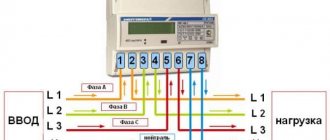
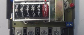
Installation and operation of meters - Checking that the meter is turned on correctly
Page 6 of 7
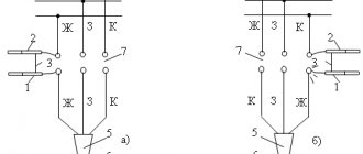
- CHECKING THE CORRECT TURN ON OF THE COUNTER
After installing and connecting the meter, its circuit is checked. The circuit is also checked in the following cases: after replacing the meter; after replacing instrument transformers; after reworking the installation of secondary switching or changing its circuit; after replacement or major repairs of the power transformer or lines supplying this switchgear; in case of doubt about the correctness of accounting. Checking the meter switching circuit is carried out in two stages: first with the connection turned off, and then with the connection turned on when there is a load on it. When checking the connection circuit of a two-element active energy meter connected to the network through instrument transformers, it is necessary to keep in mind the following: the sequence of phases connected to the terminals of the parallel windings of the meter from left to right must be straight; current and voltage of the same phase must be supplied to the windings of each rotating element of the active energy meter. The element whose terminals are brought out on the left (1st element) is supplied with the current and voltage of the leading phase (phase A), and the element whose terminals are brought out on the right is supplied with the current and voltage of the lagging phase (phase C). The voltage of phase B (middle phase) must be connected to the common point of the parallel windings. In networks with an isolated neutral, current transformers are usually not installed in this phase. The connection of the “beginning” of the series winding of each element to the generator terminals was discussed earlier. Checking the circuit with a disconnected connection. First of all, it is necessary to directly test the conductors. For dialing, an ohmmeter, handsets, a lamp or voltmeter powered by a pocket battery or a 220/12 V transformer, a bell, etc. can be used (Fig. 16). When testing, the wire being tested must be disconnected from the assembly at one end - this eliminates possible bypass circuits. As a result of the check, it is ensured that the connection made is in full compliance with the wiring diagram. After testing, the circuit is restored, leaving the parallel circuits from the voltage transformer and the grounding wire from the secondary windings of the current transformers disconnected.
Rice. 16. Checking the correct installation using a battery and a voltmeter (a), a test lamp (b), a megger (c). If parallel and series circuits are combined (Fig. 8), then it is necessary to disconnect the jumpers at the terminals of the current transformers and the meter. Then the insulation resistance of the secondary circuits is measured using a 1,000 V megger. Three measurements are made: between serial circuits and ground; between parallel circuits and ground; between parallel and serial circuits. The insulation resistance in all cases must be at least 1 MΩ. After this, the circuit is completely restored, tightening all the clamps tightly. The next stage of testing is to determine the serviceability of the voltage transformer circuits, the correctness of their connection to the meter terminals and the correspondence of the current circuit and the voltage circuit at the meter terminals.
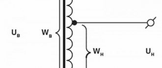
As is known, in electrical installations, phases A, B, C are painted yellow, green and red, respectively. The correct coloring of the phases, as well as the correct connection of the voltage transformer must be checked before putting the electrical installation into operation. When checking the meter switching circuit, this work is performed if it has not been done before. It consists of the following: they are convinced by inspection that the terminals of the high voltage winding of the voltage transformer A, B, C are connected to the phases of the corresponding color. If single-phase voltage transformers are used in the circuit, then it is necessary to make sure that the common point is connected to phase B. The phase sequence of the low voltage winding at the terminals of the voltage transformer cell is checked using an induction phase indicator. This device is a three-phase asynchronous motor. To check the phase rotation, it is necessary to apply voltage to the switchgear buses and turn on the voltage transformer. The phase indicator terminals A, B, C are connected to the terminals to which the corresponding terminals of the low voltage winding are connected, then briefly press the button. With direct phase rotation, the phase indicator disk rotates clockwise. This indicates that the coloring of the phases was done correctly. If the order of phase alternation is reversed (the disk rotates counterclockwise), then the coloring of the phases is incorrect. In this case, the secondary winding of the current transformer installed in the “yellow” phase is connected to the second element of the meter, and the winding of the current transformer installed in the “red” phase is connected to the first element. Next, the following measurements are made: the voltage between the terminals of the parallel windings of the meter is measured with a voltmeter. With the voltage transformers working and correctly connected, all three measurements should give a value of approximately 100 V. 1 The voltage between each terminal of the parallel winding and the ground is measured with a voltmeter. If the circuit uses a three-phase voltage transformer with a grounded zero point, then each measurement will give a value of about 100//3 = 58 V, if the circuit uses two single-phase voltage transformers connected in an open delta circuit, then two measurements will give a value of about 100 V, and the third (common phase) is equal to 0. The phases connected to the terminals of the parallel windings are determined. To do this, first find the common phase (phase B). If a three-phase transformer is used in the circuit, then it is disconnected from the high and low voltage sides. The fuse is removed from the middle phase (phase B) on the high voltage side and the transformer is put back into operation. The voltages between the terminals of parallel windings are measured. The voltage between the non-disconnected phases is about 100 V, the voltage between the disconnected and non-disconnected phases is 50 V. The voltage transformer is then switched off again on both sides, the fuse is replaced and the transformer is put back into operation. With two single-phase voltage transformers, the middle phase is found by measuring the voltages relative to ground. The voltage between the middle phase and ground is zero. The found wire from the middle phase of the voltage transformer is connected to the middle terminal of the parallel windings. The phase rotation is checked directly at the meter terminals. If the phase sequence is reversed, it is necessary to swap the wires connected to the extreme terminals of the parallel windings. Voltage phases can also be determined by phasing with parallel meter circuits with a previously tested connection circuit. You can also perform phasing with the secondary circuits of another voltage transformer with a proven circuit. This is resorted to if the voltage transformer cannot be turned off due to the operating conditions of the relay protection. For meters connected to a 0.4 kV network according to the diagram in Fig. 8, phase correspondence between the current circuit and the voltage circuit is ensured. Checking the meter switching circuit under load in installations with voltages above 1,000 V. With a uniform and symmetrical phase load, the test can be done most simply by crossing the voltage circuits on the active meter. The wire going to terminal 1 of the active meter is reconnected to terminal 3, and the wire going to terminal 3 is reconnected to terminal 1 (Fig. 9). If the counter was turned on correctly before this reconnection, then after the reconnection the counter drive should stop. This is explained by the fact that with such a scheme, the torques created by each of the two elements of the counter are equal in magnitude and opposite in direction. If the meter switching circuit is incorrect, this reconnection of wires will cause the meter disk to rotate in one direction or the other. This verification method is approximate, since a uniform and symmetrical load of the phases does not occur in all cases. Therefore, it can only be used in the absence of laboratory instruments. Let us indicate another approximate method of verification that does not require laboratory instruments. It can be used when the load is constant for several minutes. The check is carried out as follows. The number of revolutions made by the active counter disk during a certain period of time (1-3 minutes) is counted. Then the wire of the middle phase voltage circuit is disconnected and the number of revolutions is again counted for the same period of time. If the counter is turned on correctly, then in the second case the number of revolutions will be half as much. The most accurate way to check the meter switching circuit, which gives complete confidence in the result, is to remove and construct a vector diagram. This method consists in determining the position of the current vectors flowing through the successive windings of the meter. Having constructed these vectors, the correctness of turning on the meter is determined by the angle φ formed by the current vector with the voltage vector of the corresponding phase. The angle, as stated above, is measured from the current vector to the voltage vector counterclockwise. With the inductive nature of the load, the current vector lags behind the voltage vector by a certain angle lying in the range from 0 to 90°. With the capacitive nature of the load, the current vector leads the voltage vector by an angle lying within the same limits. To take vector diagrams, you can use the following devices: wattmeter, VAF-85 device, Ts-50 vector meter, phase meter, control meter. Below are the methods for taking vector diagrams using a wattmeter and using the VAF-85 device. These methods are most widespread.
Rice. 17. The principle of taking a vector diagram using a wattmeter. As is known, a wattmeter connected to the load circuit with unipolar generator terminals towards the power supply will show the power P=UIcos f. The product /cos f can be represented as a projection of the current vector / onto the voltage vector U (Fig. 17). Thus, if the voltage supplied to the wattmeter remains unchanged, then it will, on a certain scale, show the projection of the vector of the current flowing through its series winding onto the vector of the voltage applied to it. Negative wattmeter readings correspond to a negative projection of the current vector, i.e., a positive projection rotated by 180°. Knowing the projections of the current vector onto two axes, which are the linear voltage vectors, it is possible to construct the current vector itself. To take a vector diagram, use a portable wattmeter of class 0.5 with a measurement range of 5 A, 150 V, which has a power direction switch (for example, type AST-D). The procedure for making a vector diagram is as follows. The current circuit of the wattmeter is included in the cut of the serial circuit of phase A of the meter, and the wire that was connected to the beginning of the serial winding of the meter is connected to the terminal of the serial winding of the wattmeter, indicated by an asterisk. An ammeter with a measurement limit of 2.5-5 A is connected in series with the current winding of the wattmeter. In order to prevent the circuits of current transformers from breaking, these circuits must first be short-circuited at clamps specially designed for this purpose. After connecting the devices, the short circuit is removed. Next, voltages are alternately applied to the terminals of the parallel winding of the wattmeter from the terminals of the parallel windings of the meter according to the phase sequence 1-2, 2-3, 3-1. The terminal indicated by the first number is connected to the parallel winding terminal of the wattmeter, indicated by an asterisk. The wattmeter readings in divisions indicating the sign, as well as the ammeter readings are recorded in the vector diagram form. The same measurements are made by turning on the wattmeter and ammeter in a different phase. The measurements taken are considered correct if in each phase the algebraic sum of the three wattmeter readings is zero or close to zero. Then the devices are disconnected.
The vector diagram is built on a pre-prepared grid, on which the linear voltage vectors 1-2, 2-3, 3-1, their inverse vectors and phase voltage vectors are plotted. For the convenience of constructing current vectors, linear voltage vectors are divided into equal segments by straight lines perpendicular to their direction. The results of the readings of the control wattmeter on the selected scale are plotted on the vector line of the corresponding linear voltage. In this case, negative readings are deposited on the vector opposite to the linear voltage vector. Perpendiculars are restored from the ends of the resulting segments. The intersection point of two perpendiculars determines the position of the vector of the corresponding current on the vector diagram. The third perpendicular should intersect the first two at or near the same point. It is necessary to remember that to construct current vectors, linear voltage vectors are used, and the correct connection is determined by the angle formed by the current vector with the vector of the corresponding phase voltage. If the vector diagram shows that the counter is turned on incorrectly, then the connection circuit must be corrected. The correction is made at the meter terminals, after which the vector diagram is taken again. Example 4. An active energy meter is installed at an outgoing connection with an inductive load (active and reactive powers are positive). When taking a vector diagram, the following data was obtained:
| Phases | Wattmeter readings | Load, a | ||
| 1-2 | 2 -3 | 3-1 | ||
| 1 | +25 | + 10 | —35 | 3 |
| 2 | + 10 | —32 | +22 | 3 |
To construct a vector diagram (Fig. 18), we plot the segment OK on the vector line Uab, equal to 25 units on the selected scale; on the UBC vector line, segment 01, equal to 10 units; The segment From, equal to 35 units, is laid off on the line of the vector inverse to the vector Uca, since the wattmeter reading has a negative sign. From points K, I, m we restore perpendiculars. The point of their intersection is the end of the current vector /a. The vector /c is constructed in a similar way. The diagram shows that the current lags behind the corresponding phase voltage by an angle φ equal to approximately 15°. The resulting diagram corresponds to the diagram shown in Fig. 7. Consequently, the first element of the counter is switched on for current 1a and voltage Uab, and the second element is switched on for current 1c and voltage Uс in, i.e. the counter is switched on correctly. Rice. 18. Vector diagram for example 4.
The VAF-85 volt-ampere phase indicator is more convenient for making vector diagrams. It allows you to determine the magnitude and phase of current and voltage without breaking the circuit, as well as phase rotation. The volt-ampere phase indicator is a multi-limit detector device. Germanium diodes D2V operating in a half-wave circuit are used as a rectifier. To determine the current value within 1, 5 and 10 A, as well as the phase of the current without breaking the circuit, there is a current-collecting attachment - clamps. It is a detachable magnetic circuit and works as a current transformer. When determining the phase, instead of diodes in series, a mechanical rectifier is switched on with the measuring device. The excitation voltage is supplied to the mechanical rectifier from the rotor of the phase regulator (selsyn). The three-phase stator winding of the phase regulator is supplied with power from a 100 V or 220 V network. With the rotation of the phase regulator axis, the excitation phase of the mechanical rectifier changes, and, consequently, the on and off phase of its contacts relative to the phase of the current measured by the measuring device. The angle is counted using a dial attached to the axis of the phase regulator at the moment when the instrument needle reaches zero. The dial calibration zero is set at phase AB, i.e. if the terminal marked with an asterisk (*) is supplied with phase A, and the terminal marked U is supplied with phase B, then the device will show zero when the zero dial mark is set to the control line ( power from a three-phase 110 V network corresponds to the left risk, power from a 220 V network corresponds to the right risk). In this way you can check the correct operation of the device. The phase regulator also serves as a phase rotation indicator. Measurement of small alternating currents with an open circuit is carried out using a current transformer built into the device and made on a toroidal permalloy core. A measuring device is connected to the secondary winding of the current transformer. Rectification is carried out using D2V diodes connected in a full-wave circuit. Checking the correct switching on of the meter using the VAF-85 device is carried out as follows. The toggle switch “tA - IjU” is set to the IjU position; The “phase - magnitude” toggle switch is set to the “magnitude” position; the measurement limit switch is set to the “125 V” position. Linear and phase voltages are measured, and if necessary, phase B is found, as indicated above. To terminals A , B, C, respectively, three voltage phases are supplied. Having pressed the vernier handle, observe the rotation of the free axis of the phase regulator. Clockwise rotation indicates the correct phase rotation. To determine the magnitude and phase of the current, it is necessary to cover the current conductor of the serial winding of phase A with pliers so that the side of the magnetic circuit , marked with the sign *, was facing the generator end of the current conductor (similar to turning on the current circuit of a wattmeter.) The connecting plug of the clamps is plugged into the sockets * and /. The pins of the connecting forks must fit into the sockets of the clamps and into the terminals of the front panel of the device with the same symbols. The switch of measurement limits is installed to position 1, 5 or 10 A depending on the expected value of the secondary current. Three voltage phases remain connected to terminals A, B, C. In the “magnitude” toggle switch position, the value of the secondary current is recorded. Then the toggle switch is moved to the “phase” position. The dial is rotated until the instrument needle is set to zero. Then the angle is measured along the limb at the left mark (110 V). Since during one revolution of the dial the arrow is set to zero twice, it is necessary to remember that the indication at which the arrow is set to zero, moving in the same direction as the dial, is taken into account. Then clamps are used to cover the conductors connected to the series windings of other phases and repeat the measurements. The resulting angles are plotted on the form of a vector diagram relative to voltage uAv. Example 5. An active energy meter is installed on the low voltage side of the supply transformer. The nature of the load is capacitive. When taking a vector diagram with a VAF-85 device, the following data was obtained.
| Phases | The magnitude of the current, and | Corner |
| A | 3 | Inductance 15° |
| WITH | 3 | Capacity 105° |
Setting aside an angle of 15° from the linear voltage vector UАв clockwise, we construct a current vector of 1A (Fig. 19). This vector advances the voltage vector UA by an angle <рл = 15°. By subtracting an angle of 105° from the linear voltage vector Uav counterclockwise, we construct the current vector /s. It also leads the voltage vector Uc by an angle fs = 15°. Therefore, the counter is turned on correctly. Example £. The active energy meter is installed on the outgoing connection with an inductive load. When taking a vector diagram with the VAF-85 device, the following data was obtained:
| Phases | The magnitude of the current, and | Corner |
| A | 2,5 | Inductance 55° |
| WITH | 2,5 | Capacity 15° |
Rice. 19. Vector diagram for example 5. Let's construct the current vectors, as indicated earlier (Fig. 20). The current vector /A lags behind the voltage vector UA by an angle Fa = 25°. The current vector 1c should also lag behind the voltage vector by approximately the same angle. However, it lags behind the vector Fig. 20. Vector diagram for example 6. -Uс at an angle fs=75°. It is easy to verify that this vector is actually the vector of the current flowing in the neutral wire, since it is in antiphase with the current vector of phase B. From here we conclude that the neutral wire of the current transformers is connected to the beginning of the series winding of phase C of the meter. Note that to find the neutral wire of current transformers, the following method can be used. The three wires coming from the current transformers are short-circuited with jumpers on specially designed terminals, with the middle terminal being grounded. An ammeter is connected to the first terminal, the second end of which is grounded, then the jumper is disconnected from this terminal. The presence of current on the ammeter indicates that a phase wire is connected to this terminal; the absence of current indicates that the neutral wire is connected to the terminal. The measurement is carried out alternately on the other two clamps. When active and reactive energy meters are switched on together, it is enough to take a vector diagram only on the active energy meter. After this, you need to make sure by viewing the switching and checking the phasing of the voltage circuits that the same phases are connected to the windings of both meters, maintaining the same polarity. Let's consider a number of typical errors detected when checking whether the counter is turned on correctly. Blown fuses or shutdown of the voltage transformer circuit breaker after connecting the meter. In this case, the warning alarm must operate. Possible cause: connection to. terminals of the meter of the secondary circuit of the current transformers with the secondary circuits of the voltage transformer. This occurs as a result of connecting the voltage transformer circuits to the terminals of the serial windings of the meter or the secondary circuits of the current transformers to the terminals of the parallel windings. Out of three. When measuring phase-to-phase voltages, two measurements give zero, and the third - 100 V. The circuit uses two single-phase voltage transformers. Possible cause: blown fuse or broken wire on the low side of the voltage transformer. Of the three measurements of phase-to-phase voltages, one measurement gives zero, and the other two give 100 V. A three-phase voltage transformer is used in the circuit. Possible reasons: the same phase is connected to two terminals of parallel windings; fuse blown or wire break on the low voltage side in phases A or C. Of the three measurements of phase-to-phase voltages, two give 30-50 V, and the third gives 100 V. The circuit uses a three-phase voltage transformer. Possible reasons: blown fuse or break in the middle phase wire on the low voltage side; fuse blown in one of the phases on the high voltage side.
If there is a symmetrical connection load, there are no currents in the series windings of the meter, or the currents are small and do not correspond to the primary load current, or the magnitude of the currents in phases L and C is different. Possible reasons: break in the secondary circuit of the current transformers, the presence of a second ground in the secondary circuits of the current transformers, shunting of the series circuit with a wire or winding of any device, malfunction of the current transformer. If the phase-to-phase voltages are equal and there are currents in the series windings, the counter disk does not rotate. Possible causes: crossed wires going to the serial windings of phases A and C; disk overwriting. Checking the meter switching circuit under load in installations below 1,000 V. If the parallel and serial circuits of the meter are combined (Fig. 8), then it is not necessary to determine the voltage phases. It is enough to measure phase and line voltages and determine the order of phase rotation. For three-disc active energy meters (SA4U-TCh, some foreign-made meters), the order of phase rotation is indifferent and does not need to be determined. The vector diagram of the meter can be taken using a wattmeter, as indicated above. However, due to the fact that work on the meter in installations with a voltage of 0.4 kV, carried out without removing the voltage, poses a significant danger, the removal of the vector diagram, as a rule, is not performed. Other verification methods should be used. So, for three-element counters connected according to the circuit in Fig. 8, you can use a method for checking the correctness of inclusion, which consists in turning on each element one by one. By removing the jumpers on the terminal box, the other two elements are taken out of operation. The jumpers are removed and connected only when the voltage is removed from the meter terminals, after which the meter is put back into operation. If the counter is turned on correctly, then each of its elements will rotate the disk to the right. Rotation of the disk in the opposite direction indicates the flow of current in the series circuit of the element in the opposite direction. To correct the circuit, it is necessary to swap the wires connected to the series winding of this element. There is a fairly widespread opinion that with all incorrect activation of the counter, the disk rotation speed will be less than with correct activation. In reality, this statement is true only in cases where the cosph of accession is above 0.5.
- Back
- Forward
Vector diagram of currents and voltages
Digital representation of dynamic processes makes it difficult to perceive and complicates the calculation of output parameters after changes in input conditions or as a result of processing performed. A vector diagram of currents and voltages helps to successfully solve the indicated problems. Familiarization with theory and practical examples will help you master this technology.
Types of vector diagrams
Vector graphics are well suited for correctly displaying variables that determine the functionality of radio devices. This implies a corresponding change in the basic parameters of the signal along a standard sinusoidal (cosine) curve. To visualize the process, harmonic oscillation is represented as a projection of a vector onto the coordinate axis.
Using standard formulas, it is easy to calculate the length, which will be equal to the amplitude at a certain point in time. The tilt angle will indicate the phase. The total influences and corresponding changes in vectors obey the usual rules of geometry.
There are high-quality and accurate diagrams. The first ones are used to take into account mutual connections. They help make a preliminary assessment or are used to completely replace calculations. Others create taking into account the results obtained, which determine the size and direction of individual vectors.
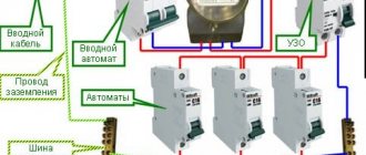
Let us assume that we need to study the change in current parameters in a circuit for different values of resistor resistance in the range from zero to infinity. In this circuit, the output voltage (U) will be equal to the sum of the values (UR and UL) on each of the elements. The inductive nature of the second quantity implies a perpendicular relative position, which is clearly visible in part of figure b). The triangles formed fit perfectly into the 180 degree circle segment. This curve corresponds to all possible points through which the end of the vector UR passes with a corresponding change in electrical resistance. The second diagram c) shows a current lag in phase by an angle of 90°.
Shown here is a two-pole element with active and reactive conductivity components (G and jB, respectively). A classic oscillatory circuit created using a parallel circuit has similar parameters. The parameters noted above can be represented by vectors that are constantly located at an angle of 90°. A change in the reactive component is accompanied by a movement of the current vector (I1...I3). The formed line is located perpendicular to U and at a distance Ia from the zero point of the coordinate axis.
Vector diagrams and complex representation
Such tools help to build visual graphic diagrams of oscillatory processes. A similar result is achieved by using complex numerical expressions. In this version, in addition to the axis with real values, an additional coordinate segment with imaginary values is used. To represent a vector, use the formula A * ei ( wt + f 0) , where:
- A – length;
- W – angular velocity;
- f0 – starting angle.
The value of the real part is A*cos*(w*t+f0). This expression describes a typical harmonic oscillation with basic characteristics.