Applicability
Tractors T-150 K, 158, DT-175S, 75 U, T-130 MG, PAZ-672, GAZ-71, 66-01, UAZ-469RKh, URAL-479
Ammeter Installation
On most cars, to monitor the operation of the power supply system, only a charge indicator lamp is used, which does not monitor the condition of the battery, charging current, voltage in the on-board network and, in addition, does not allow identifying a number of faults in the circuits. Complete information about the operation of the generator and battery can be obtained by equipping the car with an ammeter
and a voltmeter.
Ammeter
Usually it is connected to the break in the wire going from the generator to the battery.
For example, on VAZ cars between the “B+” terminals of the generator and the “+” terminals of the battery. The Ammeter
connected using a wire of suitable cross-section.
For example, the AP-111 ammeter
must be connected with a wire with a cross-section of at least 20 kV, otherwise the wire will heat up.
The Ammeter
itself may also heat up a little during operation, because There is a shunt installed inside it, which also generates heat when the current is high; this is not a malfunction.
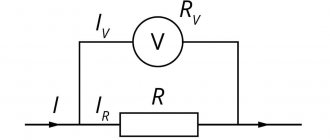
The voltmeter can be connected much easier, in any place where there is a “+”. Accordingly, one contact is connected to the body; the other is more conveniently connected to the ignition switch terminal where “+” appears when the ignition is turned on. The figure shows a typical circuit diagram for connecting an Ammeter
and voltmeter
Ammeter connection diagram
and voltmeter:
1 - battery
2 - generator
3 - mounting block
4 - ignition switch
5 - battery charge indicator lamp located in the instrument cluster
6 - ammeter
Everyone should know the rules of how to connect an ammeter. For example, such knowledge is often used when drawing up tasks for experimental rounds of school Olympiads or laboratory work.
Let's start with the principle of operation of an ammeter. The fact that it measures current is obvious simply from the name. This happens as follows: the electric current moving through the circuit also passes through the device. In this case, a torque is created, which causes the dynamic (moving) part to deflect at a certain angle. This deviation is directly proportional to the current strength. This is then displayed visually, for example, by moving an arrow or displaying a number.
Let's remember the concepts of parallel and serial connections. If you need to measure the current strength at some receiver, then its value must coincide with what passes through the ammeter. This is typical specifically for a serial connection.
However, the connection method is not the only important condition for how to connect an ammeter. The resistance of the ammeter is no less important.
If it suddenly turns out to be higher than the resistance of the receiver, when the device is connected, the circuit operation system will be disrupted, and the value of the current acting on the receiver will change.
When connecting in a gap, it does not matter whether you connect the “plus” to the power source or device. The main thing is to do it in series and not in parallel.
There are several types of ammeters. These include analog and digital. It can be used to measure both direct and alternating current. However, for any of them, the rules for connecting an ammeter remain unchanged. You just have to check what current a particular device measures. This is indicated on the device itself. If the current is direct, “=” is indicated, if alternating – “~”. This must be done, otherwise the ammeter will not work.
In addition, when working with electricity, you must follow safety rules. If you come into contact with exposed wires and are careless, there is a possibility that you will receive, if not an electrical burn, very unpleasant sensations. This is especially true for real installations, because in a school laboratory, as a rule, the circuit is powered by a battery, and the current is not too high.
Thus, a characteristic feature of the ammeter is its series connection. This limits the number of ways to connect an ammeter.
Block connection diagram
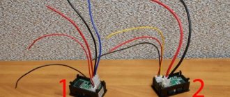
Almost all of them are small-sized and can be installed in small power supply cases. Here Aliexpress very often lends a helping hand, promptly supplying Chinese digital measuring instruments.
But for beginners, commissioning connecting an ampere-voltmeter to the circuit can be a problematic task, because the segments glow quite brightly, the color scheme is chosen very well.
Measured voltage V; current A.
And the output current easily reached almost one ampere. Connection Using a voltmeter, you can measure the current voltage in the power supply network.
For a small fee, you can find out whether the equipment works in suitable conditions. Once power is supplied to the circuit, the indicator will light up. Almost a twin of the previous voltmeter, it differs in the marking of the wires and at a reduced price.
If the connection is incorrect, the device display will show zero values. Once power is supplied to the circuit, the indicator will light up.
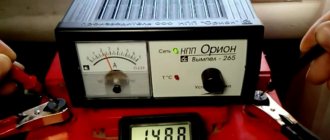
In order for it to start measuring voltages less than 3 Volts, you need to unsolder the jumper resistor R1 and apply voltage B from an external source to its right-hand contact pad in the diagram; higher voltage is possible, but not advisable - the DA1 stabilizer gets very hot. Since this information is not available on the seller’s page, I had to scour the web and sketch out a couple of diagrams. Thick wires: black minus ammeter, red ammeter output. It will be enough to connect the charger, where the voltammeter is installed, to the battery, and we will see what voltage is currently on it. Sometimes there are ammeters without a built-in current-measuring shunt.
A simple and beautiful technical solution. The lower limit is 0.1 V and 0.01 A. Since this information is not on the seller’s page, I had to rummage through the network and sketch out a couple of diagrams. The fact is that if you connect a voltmeter-ampmeter to the regulated output of the power supply, then when the voltage drops below 4. Not everyone will immediately understand which wire needs to be connected where, and the instructions are usually only in Chinese. How to connect a Voltammeter DC 100v 10a part 2
For my charging, I bought a curious copy of a Chinese voltmeter-ampmeter; I picked it up at the market and didn’t really look at it, but when I brought it home, I was scratching my head for three days about how to connect it, because I couldn’t find anything similar on the internet. I found a general description with a crooked translation on the avrobot website. ru/product_info.php?products_ >
“Connection instructions:— Red thin wire (vcc): Device supply voltage + 3.5-30 V (Note: if the measured signal is less than 30 V and have a common power supply minus, then the measured signal can also be used to power the device)— Black thin wire (ground): Supply voltage “-“, “-” measured signal 3.5-30 V— Yellow thin wire (vin): Measured signal “+” (0-100 V)— Red thick wire (i +): Current input “+” (in the power supply series are positive)— Black thick wire (i -): C. Current input “-” (Negative power wire) Calibration instructions: Due to the influence of temperature and changes in the parameters of electrical components over time, non-zero readings may appear when measuring, which is normal. This is not an error or malfunction. Solution: When the instrument is disconnected from the power, please short-circuit terminals A and B. Then take an electricity measurement, the instrument will automatically calibrate to zero. After finishing the automatic calibration, please disconnect A and B. After this, use the device as normal."
On the back wall there is an MC74HC5950 microcircuit, there are two thick wires and three thin ones. Below are photos and comments.
Connection circuits for an ammeter and a voltmeter.
44. The direction of the current and the direction of its magnetic field lines -.
Direction of current in the conductor Figures 4.3 and 4.4 show circuits for connecting a voltmeter and ammeter through voltage (VT) and current (CT) measuring transformers, respectively.
Rice.
4.3. Voltage transformer.
Voltmeter connection diagram:
?/,, U2_
primary and secondary voltages of VT;
Wv W2
- primary and secondary windings of the voltage transformer;
V
- voltmeter
Rice. 4.4.
Measuring current transformer. Ammeter connection diagram:
/р/2 - primary and secondary currents of the CT; Wv W2
— primary and secondary windings of the CT;
A
- ammeter
Ammeters, milliammeters and microammeters of various systems are used to measure current in electrical circuits. They are connected in series to the circuit, and all the current flowing in the circuit passes through them (Fig. 4.4)
It is important that during various electrical measurements the ammeter influences the electrical mode of the circuit in which it is connected as little as possible. Therefore, the ammeter must have a low intrinsic resistance compared to the circuit resistance
It is impossible to connect an ammeter to a current source (power supply) without a load, since in this case a large current will pass through its winding and it may burn out. For the same reason, the ammeter cannot be connected in parallel with the load.
Each ammeter is designed for a certain maximum current, above which the ammeter may burn out. If you need to use an ammeter to measure a current that exceeds the permissible current for a given ammeter, then a shunt is connected in parallel to the ammeter, i.e. expand the ammeter's measurement limits.
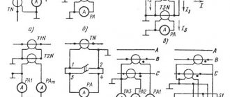
A shunt represents a relatively small but precisely known resistance. The circuit diagram for connecting an ammeter with a shunt is shown in Fig. 4.5, a.
The shunt must have four terminals to eliminate the influence of transient contact resistances on the shunt resistance. Shunts are made from manganin, an alloy whose temperature coefficient of resistance is practically zero.
Rice. 4.5.
Ammeter connection diagram:
A -
with shunt;
6
- through a current transformer;
for circuit a: 1 -
shunt;
2
- load;
for scheme b: 1
— measuring current transformer;
2
- load
Rice.
4.6. Connection diagram of three ammeters through two current transformers:
L j and L2 - the beginning and end of the primary winding of the current transformer; And, and I2 - the beginning and end of the secondary winding of the current transformer; L
- ammeters;
iA, iB, ic -
currents in phases
Rice. 4.7.
Voltmeter connection diagram:
R
- circuit resistance;
V—
voltmeter
Figure 4.6 shows a diagram of connecting three ammeters through two current transformers.
As can be seen from the diagram, a current iA passes through the first ammeter ,
through the second -
iB,
therefore, the current in the third ammeter, equal to the sum of two linear currents
iA
and
iB,
is equal to the third linear current:
ic = iA
+
iB.
Voltmeters are used to measure the voltage on a section of a circuit. The voltmeter is connected in parallel to those points of the circuit (M, N),
the voltage between which must be measured (Fig. 4.7).
The voltmeter should not change the voltage in the measured section of the circuit; for this reason, the current passing through the voltmeter must be much less than the current in the measured section.
In order for the voltmeter not to introduce noticeable distortions into the measured voltage, its resistance must be large compared to the resistance of the section of the circuit on which the voltage is measured. Any voltmeter is designed for a certain maximum voltage, but by connecting it in series with an additional resistance voltmeter /?ext you can measure higher voltages (Fig. 4.8, b).
Rice. 4.8.
Schemes for connecting an ammeter and voltmeter to an electrical circuit:
A
— without expanding the measurement limits;
b -
with expansion of measurement limits;
Yash
— shunt resistance; /?ext - additional resistance
Figure 4.9 shows a diagram of connecting a wattmeter to a single-phase high-voltage circuit through current and voltage measuring transformers.
Rice. 4.9.
Scheme for connecting a wattmeter to a single-phase high-voltage circuit through current and voltage measuring transformers:
V—
voltmeter;
A - ammeter; W—
wattmeter
Figure 4.10 shows a diagram for connecting ammeters and voltmeters to a three-phase circuit. As can be seen from the diagram, ammeters are connected through measuring CTs, and voltmeters are connected through measuring VTs. Such circuits for connecting measuring instruments are typical for high-voltage networks with voltages of 6 (10) kV and higher.
Rice. 4.10.
Connecting ammeters and voltmeters to a three-phase circuit using current and voltage measuring transformers
Current measurement.
And we'll start by measuring the current. The device used for these purposes is called an ammeter and it is connected in series to the circuit. Let's look at a small example:
As you can see, here the power supply is connected directly to the resistor. In addition, the circuit contains an ammeter connected in series with a resistor. According to Ohm's law, the current strength in this circuit should be equal to:
We obtained a value equal to 0.12 A, which exactly coincides with the practical result shown by the ammeter in the circuit