LM317 is an adjustable voltage stabilizer. It can be used to create various power supplies. It can be the basis for a current stabilizer, charger, laboratory power supply and even an audio amplifier. In order to use it, it is enough to connect it to one of the wiring diagrams indicated below.
This microcircuit is one of the most popular in the world - all because of the simplicity of its design and operation, its low cost and reliability. The latter is ensured by the presence of protection for short circuit of the terminals and overheating of the microcircuit. LM317 does not require many components as a harness. The microcircuit gained the greatest popularity among radio amateurs.
LM317 regulates voltage linearly, which is its advantage over switching converters. The microcircuit is sold in several housing options, the most popular is the LM317T version in the TO-220 housing. It was developed by Bob Dobkin in 1976 while he was working at National Semiconductor, and has been a hit in ham radio circles ever since.
LM317 circuit
The entire internal structure of the stabilizer can be seen on its diagram, taken in the datasheet. It shows three pins of the circuit: input (power is supplied to this input), regulation and output. At the adjustment pin, the signal voltage is first reduced by a one-way limiter to a stable 1.25V and serves as a reference source, and the current, along with the supply current, goes to a comparator based on an operational amplifier.
Also in the diagram you can see an output stage based on a bipolar transistor, which amplifies the current, and a protection unit against overheating and overcurrent.
To the right of the protection unit there is a current sensor, a drop in which is monitored by the protection in order to prevent damage from short circuits.
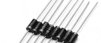
Hero of the review:
The lot consists of 10 microcircuits in a TO-220 package. The stabilizers came in a plastic bag wrapped in polyethylene foam.
Testing:
Similar stabilizers are produced by many manufacturers, here is a link to a manual from Texas Instruments. The position of the legs is as follows:
1 - adjustment; 2 - exit; 3 - entrance. We assemble a simple voltage stabilizer according to the diagram from the manual:
The results, frankly speaking, are not very good. I wouldn't dare call it a stabilizer. Next, I loaded the stabilizer with a 25 Ohm resistor and the picture completely changed:
Next, I decided to check the dependence of the output voltage on the load current, for which I set the input voltage to 15V, set the output voltage to about 5V using a trimmer resistor, and loaded the output with a variable 100 Ohm wirewound resistor. Here's what happened:
It was not possible to obtain a current of more than 0.8A, because The input voltage began to drop (the power supply is weak). As a result of this testing, the stabilizer with the radiator heated up to 65 degrees:
To check the operation of the current stabilizer, the following circuit was assembled:
Current stabilization is also good.
Well, how can there be a review without burning the hero? To do this, I reassembled the voltage stabilizer, applied 15V to the input, set the output to 5V, i.e. 10V dropped on the stabilizer, and loaded it at 0.8A, i.e. 8W of power was released on the stabilizer. The radiator was removed. The result was demonstrated in the following video: Yes, the overheating protection also works, it was not possible to burn the stabilizer.
Characteristics of LM317
- Maximum input voltage LM317 – 40V
- LM317 output voltage range – 1.2-37V
- Maximum output current for LM317 – 1.5A
- The reference voltage of the microcircuit is 0.1-1.3V
- Minimum load current – 3.5mA
- Output voltage error – 0.1%
- Power dissipation – 20W
- Operating temperature range – 0-125C
- Storage temperature range – -65-150C
- Storage temperature range – -65-150°C
Current stabilizer circuit on LM317
The device in question is most often used in LED power supplies. The following is a simple circuit that involves a resistor and a microcircuit.
The input voltage is supplied by the power supply, and the main contact is connected to the output analogue using a resistor. Next, aggregation occurs with the anode of the LED. The most popular current stabilizer circuit, LM317, described above, uses the following formula: R = 1/25/I. Here I is the output current of the device, its range varies between 0.01-1.5 A. The resistor resistance is allowed in sizes 0.8-120 Ohms. The power dissipated by the resistor is calculated by the formula: R = IxR (2).
The information received is rounded up. Fixed resistors are produced with a small spread of final resistance. This affects the receipt of calculated indicators. To resolve this problem, an additional stabilizing resistor of the required power is connected to the circuit.
Types of LM317
The microcircuit is sold in several housing options, depending on the need for size, load and connection, as well as the type of circuit installation - everyone can choose the option that suits them best.
The most popular is the LM317T in a TO-220 1.5 Ampere package. This is considered a universal option, as it can be used in surface-mounted as well as surface-mounted applications. A radiator in such a case allows you to remove excess heat and experience more severe loads than its counterparts, and if necessary, it can be attached to a larger radiator.
Connection features
On the lm317t, the switching circuit is quite simple and consists of a minimum number of components. However, their number depends on the purpose of the device. If a voltage stabilizer is being manufactured, it will require the following parts: Rs - shunt resistance, which also acts as a ballast. Select a value of about 0.2 Ohm if you want to provide a maximum output current of up to 1.5 A.
The resistive divides with R1, R2, connected to the output and the housing, and the regulating voltage comes from the middle point, forming deep feedback. Due to this, a minimum ripple coefficient and high stability of the output voltage are achieved. Their resistance is selected based on the ratio 1:10: R1=240 Ohm, R2=2.4 kOhm. This is a typical voltage regulator circuit with an output voltage of 12 V.
If you want to construct a current stabilizer, you will need even fewer components: R1, which is a shunt. They set the output current, which should not exceed 1.5 A. To correctly calculate the circuit of a particular device, you can always use the lm317 calculator. As for the calculation of Rs, it can be determined using the usual formula: Iout. = Uop/R1. On lm317, the LED current stabilizer is of quite high quality, which can be made of several types depending on the power of the LED: to connect a single-watt LED with a current consumption of 350 mA, you must use Rs = 3.6 Ohms.
Its power is selected to be at least 0.5 W; To power three-watt LEDs, you will need a resistor with a resistance of 1.2 Ohm, the current will be 1 A, and the dissipation power will be at least 1.2 W. With lm317, the LED current stabilizer is quite reliable, but it is important to correctly calculate the shunt resistance and select its power.
A calculator will help in this matter. Also, various powerful lamps and homemade spotlights are made using LEDs and based on this MS.
LM317 connection
LM317 has the following pin configuration in different packages:
The minimum connection diagram consists of two resistance resistors and three capacitors connected according to the diagram. In accordance with the resistance characteristics, the output voltage will be determined.
The LM317 has two main parameters: its reference voltage, as well as the current flowing out at the trim pin. Reference voltage (Vref) is the voltage that the stabilizer maintains across resistance R1. It is unstable and varies from batch to batch by an average of 0.1V, so for calculations it is better to keep in mind the average value of 1.25V. For serious projects, it is worth measuring it for each instance used. Accordingly, following the diagram, if we close resistor R2, then at the output we will get a reference voltage of 1.25V, and with an increase in the voltage at R2, the output voltage will also increase. Thus, LM317 constantly compares the output voltage through a resistive divider with the reference, therefore, by changing the resistance, we change the output voltage.
The current flowing out at the adjustment (Iadj) is parasitic. According to manufacturers, it ranges from 50 to 100 μA, but in reality it can reach 500 μA. Because of this, for stability of the output voltage, the resistance of R1 should not be higher than 240 Ohms, so that a current of less than 5 mA does not pass through the divider.
All you need is to substitute your R1 value into this formula R2=R1*((Uo/Uref)-1).
Also, don't forget about cooling. The greater the difference between the input and output current, the more the stabilizer will heat up, which will lead to problems with its operation. The parameters described by the manufacturer can only be achieved using additional cooling in the form of a radiator.
Pin assignment and operating principle
It was mentioned that LM317 belongs to the class of linear stabilizers. This means that the output voltage is stabilized due to the redistribution of energy between the load and the control element.
The transistor and the load form an input voltage divider. If the voltage set at the load decreases (due to a change in current, etc.), the transistor opens slightly. If it increases, it closes, the division coefficient changes and the voltage at the load remains stable. The disadvantages of this scheme are known:
- it is necessary that the input voltage exceeds the output;
- the regulating transistor dissipates a lot of power;
- The efficiency, even theoretically, cannot exceed the ratio Uout/Uin.
But there are serious advantages (relative to pulse circuits):
- relatively simple and inexpensive microcircuit;
- requires minimal external strapping;
- and the main advantage is that the output voltage is free from high-frequency parasitic components (power supply interference is minimal).
Standard microcircuit connection diagram:
- input voltage is applied to the Input pin;
- to output Output – output;
- on Ajust – the reference voltage on which the output depends.
Resistors R1 and R2 set the output voltage. It is calculated using the formula:
Uout=1.25⋅ (1+R2/R1) +Iadj⋅R2.
Iadj is the parasitic current of the setting pin, according to the manufacturer it can be within 5 µA. Practice shows that it can reach values an order of magnitude or two higher.
Typical LM317 circuits
As stated, the LM317 is used to create regulated and unregulated power supplies, however, it can also be used as the basis of a current regulator when creating LED drivers that maintain current in the circuit regardless of the input voltage. The applications described in the datasheet alone are enough to fill a separate book, so we will analyze several of the most popular circuits based on this stabilizer.
Adjustable power supply (1.2-37V)
All that is needed to create it is to replace R2 with a variable resistor, and also add a transformer with a diode bridge to the input. When using it, it is worth considering that the microcircuit has a reference voltage of 1.25V, so it will be minimal for this circuit.
Adjustable power supply (0-37V)
If you need full regulation from 0V, then circuit manufacturers suggest connecting a 10V negative voltage source to the circuit.
You can wind an additional coil on the power supply transformer and connect its leads after the diode bridge as follows:
Or you can use a negative voltage source that will be powered from the main winding.
Thus, you will get a simple laboratory power supply.
LED Driver (Current Stabilizer)
With this circuit you can power fairly powerful LEDs and LED strips. All you need is to know the current consumed and, based on it, select the resistance using the formula.
It uses the same principle as the simplest circuit, but instead of a resistive divider, a current sensor is installed. The more current the load consumes at the output, the greater the voltage drop will be observed across the sensor. It is monitored by the IC and it increases or decreases the voltage to maintain a stable current. Even in the event of a short circuit, the current will remain at the stable level that was set.
Charger
The circuit of this charger is taken from the datasheet and has an output voltage of 6V with a limit of 0.6A. By changing the resistance of resistors R1 and R2, it is possible to adjust the voltage to suit your needs, and with the help of resistor R3 - the current. It is suitable for powering batteries of phones, tools and household appliances.
AC voltage regulation
Since two LM317 can regulate not only positive, but also negative sine wave oscillations, they can be used to create an AC regulator. You can see that the circuit is quite simple and does not require many components:
Example of voltage stabilization on LM317
Let's say you need to supply 12 volts to the microcircuit and adjust it to 5. Based on the formula given above, in order for LM317 to output 5 volts and act as a voltage regulator, the value of R2 should be 720 Ohms.
Assemble the above diagram. Then use a multimeter to check the output voltage by placing its probes on the 1uF capacitor. If the circuit is assembled correctly, then its output will be about 5 volts.
Input capacitor C1 can not be used if the microcircuit body is located at least 15 centimeters from the input smoothing filter. An output capacitor C2 is added to smooth out transients.
Now replace resistor R2 and replace it with a value of 1.5 kOhm. Now the output should be about 10 V. This is the advantage of these microcircuits. You can set them to any voltage within the range specified in its specifications.
Principle of operation
Let's assemble a simple voltage stabilizer using LM317 according to the diagram.
Let's connect a constant power source to the Vin input. As was written earlier, an input voltage must be supplied to these contacts, which the microcircuit will then reduce depending on the load. It must be greater than the output.
Let's say using this circuit you need to get 5 V load. Therefore, more than 5 volts must be applied to the Vin input. As a rule, if the LM317 chip is not a low-dropout regulator, you need the input voltage to be about 2 volts higher than the output voltage. Since we want 5 volts output, we will supply 7 volts to the regulator.
A low dropout regulator is a device with a low dropout across the junction, approximately 1 to 1.5 volts. A single NPN transistor is usually used as a regulating element.
The Adj contact allows us to adjust the output voltage to the level we want. Let's calculate what value of resistance R2 will give 5 volts at the output of the device. Using the formula for the output voltage, you can find out the value of resistance R2.
Since the resistance of R1 is 240 Ohms, and the output voltage is 5 V, then R2, according to the formula, will be equal to 720 Ohms. Thus, with a value of R2 = 720 Ohms, LM317 will output 5 V when more than 5 Volts are applied to its input.
Current Driver
The current driver (LED Driver) maintains the current and voltage in the load circuit, regardless of the constant power supplied to it. It is known that an LED is a semiconductor device that should be powered with the current specified in the characteristics of the LED.
Using the stabilization circuit as shown in the DataSheet, you can assemble a simple current driver circuit on the LM317.
For its operation, knowing the current consumed by the LED, it is necessary to select the resistance of the trimming resistor R1. For low-power LEDs, the current consumption is about 20 mA or 0.02 A. To select the required resistance, use the formula where Iout is the current at the output of the microcircuit required to power the LEDs.
Using the formula, we obtain the value of the resistor with a resistance of 62.5 Ohms. To avoid overheating of the microcircuit, select the required resistor power according to the formula.
By assembling the circuit and applying power, we get the simplest current stabilization driver for LEDs. The LED will turn on with the required brightness, which will not depend on the constant power supplied to the input of the microcircuit.
The value of the required resistor R1 can be selected using a conventional tuning wirewound resistor with a resistance of 0.5 kOhm. To do this, first check its resistance between the middle and any of the extreme terminals. Using a multimeter, rotating the control rod, we achieve a resistance value of 500 Ohms, so as not to burn out the connected LED when turned on.
Then they are connected to a circuit with an LED. To select the appropriate resistor value, after applying power, change the resistance of the trimming resistor to the required LED current.
Online calculator
To calculate the parameters of radioelements in circuits with LM317, there are many online calculators on the Internet:
- to calculate resistor R2, with a known output voltage and resistance of resistor R1;
- to calculate the voltage at the output of the stabilizer, with a known resistance of two resistors (R1 and R2);
- to calculate the resistance and power of a resistor, with a known current value at the output of the microcircuit, etc.
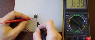
How to test LM317?
Unlike transistors, this microcircuit cannot be checked with a multimeter. This method does not in any way guarantee correct operation due to the large number of internal elements not connected to the terminals. Therefore, if one of them fails, then checking it with a multimeter will be problematic. The easiest way to test the operation of the LM317 is to create a simple stand on a breadboard, and it can be powered only by a battery.
This way, you can quickly verify that an item is in full working order, even if you need to check several pieces.
Application of LM317
The diagrams given above are only a small part, the basis, compared to what can be done with this stabilizer. It can be used in almost all circuits that require a constant power supply of up to 40 V. Here are some applications described in the official technical document of this chip:
- Personal computers
- Digital cameras
- ECG
- Internet switches
- Biometric sensors
- Electric motor drivers
- Portable chargers
- PoE
- RFID readers
- Appliances
- X-ray machines
As you can see, even the manufacturer himself expects the widest possible use of this element, to say nothing of home-made manufacturers who are ready to present the most unusual circuits using LM317.
Connection
The calculation of the LM317 current stabilizer is based on several connection methods. Below are the basic diagrams:
- If you use a powerful transistor like Q1, you can get an output current of 100 mA without a microassembly heatsink. This is quite enough to control the transistor. As a safety net against excess charge, protective diodes D1 and D2 are used, and a parallel electrolytic capacitor performs the function of reducing extraneous noise. When using transistor Q1, the maximum output power of the device will be 125 W.
- Another circuit ensures current limitation and stable operation of the LED. A special driver allows you to power elements from 0.2 watts to 25 volts.
- The next design uses a step-down transformer from an alternating network from 220 W to 25 W. Using a diode bridge, the alternating voltage is transformed into a constant value. In this case, all interruptions are smoothed out by a capacitor of type C1, which ensures stable operation of the voltage regulator.
- The following connection diagram is considered one of the simplest. The voltage comes from the secondary winding of the transformer at 24 volts, is rectified when passing through the filter, and the output is a constant reading of 80 volts. This avoids exceeding the maximum voltage supply threshold.
It is worth noting that a simple charger can also be assembled based on the microcircuit of the device in question. You will get a standard linear stabilizer with an adjustable output voltage. The microassembly of the device can function in a similar role.
Increasing the maximum output current
There are two ways to increase the maximum output current. If you need to get more than 1.5A, then you can either connect several chips in parallel, or connect a power transistor.
In the first case, it is enough to connect resistors with low resistance to the output of the stabilizers. They are needed to equalize currents.
However, it is not always rational to use several chips. Therefore, a transistor comes to our aid. In this case, it will be enough to add it and a resistor as a harness to it.
If the load draws a small current, it will pass through the chip without affecting the transistor. And when it increases, almost all the current will pass through the transistor, leaving a small part of it for the stabilizer. But when using this circuit, there is internal protection inside the LM317 from short circuit.
A little theory:
Stabilizers are linear
and
pulsed
.
A linear stabilizer
is a voltage divider, the input of which is supplied with an input (unstable) voltage, and the output (stabilized) voltage is removed from the lower arm of the divider.
Stabilization is carried out by changing the resistance of one of the divider arms: the resistance is constantly maintained so that the voltage at the output of the stabilizer is within the established limits. With a large ratio of input/output voltages, the linear stabilizer has low efficiency, since most of the power Pdis = (Uin - Uout) * It is dissipated as heat on the control element. Therefore, the control element must be able to dissipate sufficient power, that is, it must be installed on a radiator of the required area. The advantage
of a linear stabilizer is its simplicity, lack of interference and a small number of parts used.
Disadvantage
: low efficiency, high heat generation.
A switching
voltage stabilizer is a voltage stabilizer in which the regulating element operates in a switching mode, that is, most of the time it is either in a cutoff mode, when its resistance is maximum, or in a saturation mode - with minimal resistance, which means it can be considered as a switch .
A smooth change in voltage occurs due to the presence of an integrating element: the voltage increases as it accumulates energy and decreases as it is released into the load. This operating mode can significantly reduce energy losses, as well as improve weight and size indicators, but it has its own characteristics. The advantage of
a pulse stabilizer is high efficiency and low heat generation.
Disadvantage
- a larger number of elements, the presence of interference.
Analogs LM317
What to do if it is not possible to use LM317? You can use its analogues. The twin brothers of this component are UPC317, GL317, ECG1900 and SG317. The domestic analogue is KP142EH12A, and there is also a KP142EN12 with a fixed voltage.
If the LM317 is not enough power for your project, then you can use more powerful options:
- LM350AT and LM350T – maximum output current 3A and power 25W
- LM350K – current 3 A and power 30 W
- LM338T and LM338K – current 5 A
All these microcircuits have the same pins, so the circuits do not have to be changed in any way.
Safe operation of LM317
It is worth remembering the operational characteristics of the radio component and not using it in critical conditions. The power dissipation according to official information is 20 W, and the difference between the input and output voltages should not exceed 40 V. During soldering, the temperature should not exceed 260 C. It can be used at temperatures from 0C to 125C, and stored from -65C to 150C. All these are officially declared characteristics; in reality, they may differ from instance to instance and be underestimated.
You should not use the element at the maximum and minimum indicated values. With such operation, the level of stability and reliability will drop significantly. It is also highly advisable to use a radiator to remove heat, since otherwise the stated characteristics may not coincide with the real ones.
DataSheet
Description
LM217, LM317 - monolithic integrated circuits in TO-220, TO-220FP and D²PAK packages intended for use as voltage stabilizers. Can support a load current of more than 1.5 A and an adjustable voltage ranging from 1.2 V to 37 V. The rated output voltage is selected using a resistive divider, which makes the device very easy to use. The domestic analogue is the KR142EN12A microcircuit.
Properties
- Output voltage from 1.2 V to 37 V
- Output current 1.5 A
- 0.1% adjustment deviation in line and load
- Variable control for high voltages
- Full set of protection: current limitation; overheat shutdown; SOA quality control
Marking
| TO-220 | TO-220 | D²PAK | TO-220FP |
| LM217T | LM217T-DG | LM217D2T-TR | |
| LM317T | LM317T-DG | LM317D2T-TR | LM317P |
| LM317BT |
Pin layout
Rice.
1 Top view You can buy the LM317 here.
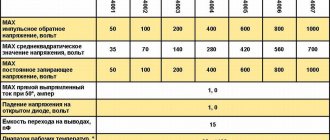
Maximum values
Absolute maximum values
| Designation | Parameter | Meaning | Unit change | |
| VI-VO | Input voltage | 40 | IN | |
| IO | Output current | Internally limited | A | |
| TOP | Operating temperature of pn junction for: | LM217 | from - 25 to 150 | °C |
| LM317 | 0 to 125 | |||
| LM317B | from -40 to 125 | |||
| P.D. | Power dissipation | Internally limited | W | |
| TSTG | Storage temperature | from - 65 to 150 | °C | |
Thermal characteristics
| Designation | Parameter | D²PAK | TO-220 | TO-220FP | Unit change |
| RthJC | Thermal resistance crystal-case | 3 | 5 | 5 | °C/W |
| RthJA | Thermal resistance crystal-medium | 62.5 | 50 | 60 | °C/W |
Scheme
Rice. 2 Internal circuit
Electrical characteristics
Electrical characteristics of LM217
VI - VO = 5 V, IO = 500 mA, IMAX = 1.5 A and PMAX = 20 W, TJ = - 55 to 150 °C unless otherwise noted.
| Designation | Parameter | Conditions | Min. | Type. | Max. | Unit change | |
| ΔVO | Instability of the output voltage in the line | VI - VO = 3 - 40 V | TJ = 25°C | 0.01 | 0.02 | %/IN | |
| 0.02 | 0.05 | ||||||
| ΔVO | Instability of output voltage at load | VO ≤5 V IO from 10 mA to IMAX | TJ = 25°C | 5 | 15 | mV | |
| 20 | 50 | ||||||
| VO ≥5 V IO from 10 mA to IMAX | TJ = 25°C | 0.1 | 0.3 | % | |||
| 0.3 | 1 | ||||||
| IADJ | Current at the control terminal | 50 | 100 | µA | |||
| ΔIADJ | Current change at the control terminal | VI - VO from 2.5 to 40 V IO from 10 mA to IMAX | 0.2 | 5 | µA | ||
| VREF | Reference voltage | VI - VO 2.5 to 40 V IO = 10 mA to IMAX, PD ≤ PMAX | 1.2 | 1.25 | 1.3 | IN | |
| ΔVO/VO | Output voltage, temperature stability | 1 | % | ||||
| IO(min) | Minimum load current | VI - VO = 40 V | 3.5 | 5 | mA | ||
| IO(max) | Maximum load current | VI - VO ≤ 15 V, PD < PMAX | 1.5 | 2.2 | A | ||
| VI - VO = 40 V, PD < PMAX, TJ = 25°C | 0.4 | ||||||
| eN | Output noise voltage (percentage of VO) | B = 10 Hz to 100 kHz, TJ = 25°C | 0.003 | % | |||
| SVR | Supply voltage deviation (1) | TJ = 25°C, f = 120 Hz | CADJ=0 | 65 | dB | ||
| CADJ=10 µF | 66 | 80 | |||||
1. CADJ is connected between the control pin and ground.
Electrical characteristics of LM317
V I - VO = 5 V, IO = 500 mA, IMAX = 1.5 A and PMAX = 20 W, TJ = 0 to 150 °C unless otherwise noted.
| Designation | Parameter | Conditions | Min. | Type. | Max. | Unit change | |
| ΔVO | Instability of the output voltage in the line | VI - VO = 3 - 40 V | TJ = 25°C | 0.01 | 0.04 | %/IN | |
| 0.02 | 0.07 | ||||||
| ΔVO | Instability of output voltage at load | VO ≤5 V IO from 10 mA to IMAX | TJ = 25°C | 5 | 25 | mV | |
| 20 | 70 | ||||||
| VO ≥5 V IO from 10 mA to IMAX | TJ = 25°C | 0.1 | 0.5 | % | |||
| 0.3 | 1.5 | ||||||
| IADJ | Current at the control terminal | 50 | 100 | µA | |||
| ΔIADJ | Current change at the control terminal | VI - VO from 2.5 to 40 V IO from 10 mA to 500 mA | 0.2 | 5 | µA | ||
| VREF | Reference voltage | VI - VO from 2.5 to 40 V IO = from 10 mA to 500 mA, PD ≤ PMAX | 1.2 | 1.25 | 1.3 | IN | |
| ΔVO/VO | Output voltage, temperature stability | 1 | % | ||||
| IO(min) | Minimum load current | VI - VO = 40 V | 3.5 | 10 | mA | ||
| IO(max) | Maximum load current | VI - VO ≤ 15 V, PD < PMAX | 1.5 | 2.2 | A | ||
| VI - VO = 40 V, PD < PMAX, TJ = 25°C | 0.4 | ||||||
| eN | Output noise voltage (percentage of VO) | B = 10 Hz to 100 kHz, TJ = 25°C | 0.003 | % | |||
| SVR | Supply voltage deviation (1) | TJ = 25°C, f = 120 Hz | CADJ=0 | 65 | dB | ||
| CADJ=10 µF | 66 | 80 | |||||
1. CADJ is connected between the control pin and ground.
LM317B Electrical Specifications
VI - VO = 5 V, IO = 500 mA, IMAX = 1.5 A and PMAX = 20 W, TJ = -40 to 150 °C unless otherwise noted.
| Designation | Parameter | Conditions | Min. | Type. | Max. | Unit change | |
| ΔVO | Instability of the output voltage in the line | VI - VO = 3 - 40 V | TJ = 25°C | 0.01 | 0.04 | %/IN | |
| 0.02 | 0.07 | ||||||
| ΔVO | Instability of output voltage at load | VO ≤5 V IO from 10 mA to IMAX | TJ = 25°C | 5 | 25 | mV | |
| 20 | 70 | ||||||
| VO ≥5 V IO from 10 mA to IMAX | TJ = 25°C | 0.1 | 0.5 | % | |||
| 0.3 | 1.5 | ||||||
| IADJ | Current at the control terminal | 50 | 100 | µA | |||
| ΔIADJ | Current change at the control terminal | VI - VO from 2.5 to 40 V IO from 10 mA to 500 mA | 0.2 | 5 | µA | ||
| VREF | Reference voltage | VI - VO from 2.5 to 40 V IO = from 10 mA to 500 mA, PD ≤ PMAX | 1.2 | 1.25 | 1.3 | IN | |
| ΔVO/VO | Output voltage, temperature stability | 1 | % | ||||
| IO(min) | Minimum load current | VI - VO = 40 V | 3.5 | 10 | mA | ||
| IO(max) | Maximum load current | VI - VO ≤ 15 V, PD < PMAX | 1.5 | 2.2 | A | ||
| VI - VO = 40 V, PD < PMAX, TJ = 25°C | 0.4 | ||||||
| eN | Output noise voltage (percentage of VO) | B = 10 Hz to 100 kHz, TJ = 25°C | 0.003 | % | |||
| SVR | Supply voltage deviation (1) | TJ = 25°C, f = 120 Hz | CADJ=0 | 65 | dB | ||
| CADJ=10 µF | 66 | 80 | |||||
1. CADJ is connected between the control pin and ground.
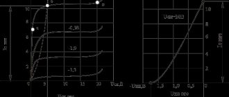
Typical characteristics
Rice. 3 Output current from input-output differential voltage Fig. 4 Voltage drop versus pn junction temperature Fig. 5 Reference voltage versus pn junction temperature
Rice. 6 Simplified diagram of a controlled stabilizer
Application
Stabilizers of the LM217, LM317 series support a reference voltage of 1.25 V between the output and the control pin. It is used to maintain a constant current through a voltage divider (see Fig. 6), which gives an output voltage VO calculated by the formula:
VO = VREF (1 + R2/R1) + IADJ R2
Regulators were designed to reduce the IADJ current and keep it constant in the line as the load changes. Generally, the deviation IADJ × R2 can be neglected. To meet the above requirements, the stabilizer returns the quiescent current to the output pin to maintain the minimum load current. If the load is insufficient, the output voltage will rise. Since LM217, LM317 regulators have an ungrounded "floating" output and only see the difference between the input and output voltage, for sources with very high voltage relative to ground, it is possible to stabilize the voltage for as long as possible until the maximum difference between the input and output voltage is exceeded. In addition, you can easily assemble a programmable stabilizer. By connecting a constant resistor between the output and the control, the device can be used as a precision current stabilizer. Performance can be improved by adding containers as described below:
- There is a 1 µF capacitor at the bypass input.
- There is a 10 µF capacitor on the control pin to improve ripple suppression by 15 dB (CADJ).
- Tantalum electrolytic capacitor at the output to improve transient response. In addition to capacitors, you can add protective diodes, as shown in Fig. 7. D1 is used to protect the stabilizer against input short circuit, D2 to protect against output short circuit and capacitance discharge.
Rice. 7 Voltage stabilizer with protective diodes
Rice. 8 15 V stabilizer with smooth switching
Rice.
9 Current regulator IO = (VREF / R1) + IADJ = 1.25 V / R1
Rice. 10 5 V stabilizer with electronic shutdown
Rice. 11 Stabilizer with digital voltage regulation
R2 corresponds to the maximum output voltage value
Rice. 12 Charging for 12 V battery
RS sets the output charging resistance, calculated by the formula ZO = RS (1 + R2/R1). The use of RS makes it possible to reduce the charge level when the battery is fully charged.
Rice. 13 6 V charger, current limited
*R3 sets the maximum current (0.6 A for 1 Ohm).
*C1 is recommended to be connected to filter input transients.
If you find an error, please select a piece of text and press Ctrl+Enter.