Scope of application
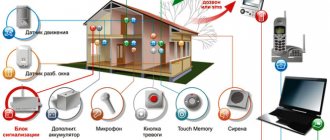
Pulse relays are used at various facilities where automated systems require control of one or more places.
Main areas:
- organization of lighting in houses, supermarkets and other buildings;
- arrangement of a smart home;
- railways - provision of dispatching and telecontrol;
- transmission of operating signals;
- protection of more powerful equipment when the relay turns on/off other equipment;
- supply of electricity taking into account the timer readings;
- alarm operation, etc.
Pulse relays provide complete controllability of the equipment, which makes them the best solution when implementing different power supply schemes.
What requirements must PTFs meet?
Finally, we note what rules modern fog lights must meet:
- In order to illuminate the road surface well, this type of optics must have a clear beam boundary at the top. Thus, the light in the headlights is scattered slightly above the horizontal plane.
- If the car manufacturer has not provided space for PTF fasteners, do not install them above the headlights under any circumstances. Try to place them as close to the roadway as possible. The lower this optics is, the better it will “break” the foggy barrier in front of you. But don’t forget about the car’s ground clearance. If the headlight is located at a distance of 10 centimeters from the asphalt, then during rainy weather it will constantly get wet, and water that gets inside the reflector will linger there for several weeks. And throughout this period the glass will be cloudy, and the quality of lighting will deteriorate significantly. On cars like the VAZ “classic”, the optimal solution to the problem is to install the PTF under the steel bumper. This way you will “kill two birds with one stone.” Firstly, at such a distance from the road the headlight will never get wet, and secondly, it looks very attractive and does not disfigure the appearance of the car. But where there is no point in installing PTF at all is on the roof (owners of SUVs often do this). The benefit from such illumination is zero, but such a technique will be fully blinding.
- If this is not factory optics, it is advisable to purchase it with special plugs. This way you will significantly increase the service life of your headlights and ensure their high safety when driving on rough terrain. And the cap protects the fog lights all year round at any time of the day.
- During operation, it is important to prevent clouding or fogging of the optics glass. To prevent this, you should regularly treat their surface with special polishes (at least once every 2-3 months).
What are there
Pulse relays are of two types - electronic and electromagnetic.
The former are based on a special board with a microcontroller and a triac, and the latter are based on a coil that operates on the electromagnetic principle and has a classic switching mechanism. Let's consider each of them separately.
Electromechanical
The peculiarity of pulse electromechanical relays is that they consume electricity only at the moment the contact group is activated. Thanks to the locking mechanism, the reliability of the device increases and energy consumption decreases.
Such a system reliably protects against voltage surges that can lead to erroneous operation of the equipment.
Structurally, pulse relays operating on the electromechanical principle consist of the following elements:
- coil;
- contact Group;
- on/off buttons.
Electromagnetic relays are more reliable and easy to use. They are not afraid of interference in the network, and there are no strict requirements for the installation location.
Electronic (digital)
These pulse relays are based on an electrical circuit based on microcontrollers. This design solution allows you to “flash” more functionality (for example, a shutdown timer).
The presence of additional options allows you to use relays when organizing complex lighting systems.
Structurally they consist of the following elements:
- Microcontrollers.
- Coil-electromagnet.
- Semiconductors.
The advantage of electronic relays is greater choice and versatility. They can be used for networks with different voltages, namely 12, 24, 130 or 220 V.
Available with different types of mounting: DIN for electrical panels or for classic installation.
Disadvantages include less reliability and higher wiring requirements. During installation, it is recommended to use a shielded cable to protect against interference.
Thermal mode of the device
The IRF9310 transistor in the open state has a resistance of only 6.8 mOhm. With a current of 11 A consumed by the headlights, the power dissipation does not exceed 0.822 W. According to the transistor specification, a copper plate with an area of 6.5 cm2 is needed for heat removal. In a small relay volume, this is difficult to do, and for cooling, a relay leg is used, to which the drain of the transistor is soldered as close as possible. This ensures acceptable heating up to 55–60 °C.
ATtiny13 controller program
The finite state machine implemented by the program provides 6 states: 1. waiting for the headlights to turn on with the ignition off; 2. smooth heating; 3. waiting for the next light to turn on; 4. fast heating; 5. lamps are turned on completely; 6. switch off with hold.
The choice of states is determined by interrupt handling at the moment of timer overflow. PWM control is implemented by a timer in phase-correct PWM mode. The timer and controller have an operating frequency of 1.2 MHz, and the PWM output signal is 2353 Hz. When the power supply drops below 2.7 V, the microcontroller goes into a reset state. To do this, the Brown-out detector voltage protection is enabled in the settings. The delay is set to 0.064 seconds. to return the machine to its original state after a reset.
The difference between bistable and conventional relays
The peculiarity of simple relays is that when voltage is applied to the coil, the contact group is closed or opened. When the potential is removed, the contacts return to their original position.
This principle is actively used in automobile power supply systems.
Pulse (bistable) relays are triggered when a pulse is applied. For example, when the first signal arrives, the device closes, and when the second signal arrives, it opens. In this case, commands can be given with different polarities.
Connection errors
To avoid problems, you need to take into account the main mistakes and avoid them:
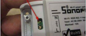
- Poor contact of connections. You should not make twists and wrap them with electrical tape, this is a short-lived option.
The wires should be connected to the relay through the connector to ensure reliable contact. - Installing the relay in an inappropriate location. If it is not secured and is exposed to changes in humidity, it can quickly fail.
- Using thin wires. They will overload and heat up during operation, which will eventually cause the insulation to melt. It is better to buy an option with a margin of safety.
- There is no fuse in the system. In case of voltage surges and short circuits, the headlights will fail or the wiring may catch fire.
Connecting headlights via a relay is not difficult, since everything you need is sold in car dealerships, and the circuit is very simple. The main thing is to ensure reliable contact of connections and lay the wiring carefully so that it is not damaged during operation.
Main technical characteristics
When choosing pulse relays, you need to look at the technical characteristics of the equipment.
The main parameters include:
- I out - output current, represents the largest parameter in the coil after the armature exits;
- K is the return coefficient, which is calculated as the ratio of two currents for the armature: output and retraction;
- I W - pull-in current, the smallest current parameter of the coil when the armature returns to its original position;
- I mouth - setting current, which is set in the relay;
- U nom, I nom - nominal parameters of voltage and current, respectively;
- I cf is the operating current at which the contact group closes/opens when a control signal is applied.
When studying the characteristics of a pulse relay, it is worth paying attention to other parameters:
- rated frequency;
- degree of protection against moisture/dust;
- application category;
- weight;
- pulling force of contact clamps;
- maximum cross-section of the connected wire;
- mechanical / switching resistance;
- own power consumption;
- control current;
- application category;
- controlled current, etc.
The manufacturer's technical specifications often indicate a range of operating temperatures, a group of operating conditions from the perspective of the influence of mechanical factors, recommendations for altitude above sea level and permissible humidity/pollution.
During installation, you will need data on the mounting features and location in space (horizontal, vertical, arbitrary, etc.).
Implementation of a lighting control circuit using intermediate relays
My regular reader Nikolai put together the proposed scheme. The task was to turn on the lights from four places in a large public room, and use switches rather than buttons. There were 3 wires connected to each switch, and touching the tiles was not an option at all.
Build process:
Assembling a circuit using switches and relays
Please note that Wago 221 5-pin terminals are used, mounted on a DIN rail through a special holder.
I have a lot of articles on Wago, here is the main one.
Assembling and debugging a lighting control circuit using a relay
Finder relays with a 230V coil are used as intermediate relays.
Lighting control circuit using a relay and modular contactor
Since powerful spotlights are used, the power of which is more than 2 kW, a modular contactor with a contact current of 25A is used. The contactor separates the “logical” and power parts.
Please note that this contactor has 3 positions – On, Automatic (coil controlled), and Off.
The scheme turned out to be as follows:
Scheme with 2 pass-through switches, 2 relays and a modular contactor
For those interested, read how a contactor is fundamentally different from a starter.
By the way, I used a similar modular contactor in a homemade ATS to connect a generator to the house. There I recommended connecting the coil in series with a resistor to reduce its heating when turned on for a long time.
And the installation process in the utility room (electrical room) looked like this:
Installation of a lighting control system from 4 places
The cable used is NYM, copper monocore round.
Thank you for your attention, please share your opinions and ask questions in the comments!
Device
There is a large selection of pulse relays on the market, differing in technical characteristics and design features.
The simplest pulse relay consists of the following elements:
- Coil. An electrical element consisting of a non-magnetic base with a wound copper wire. Electric cardboard or textolite can be used as a base. The task is the formation of an electromagnetic field and its effect on a magnet.
- Core. Made on a ferromagnetic base. When a magnetic field appears, it is in the zone of its action and is used as a moving element.
- Contacts. They are metal elements that are triggered or opened when a pulse is given. They can be fixed or move when the core moves.
- Resistor, capacitance and other elements. Used to create logic for the operation of a pulse relay and display its position (on or off).
- Timer. Sets the time delay until triggering. Not installed on all types of devices. Allows you to issue or remove a command after a while, which expands the functionality of the device.
Electronic devices have a simpler design, because they are based on a microprocessor. But the principle of operation, which will be discussed below, remains the same.
Why can relays be useful to you in your home?
I think for the same corridors and interfloor stairs, large hallways, external and landscape lighting, opening electric locks, irrigation systems, various pumps and exhaust fans.
By the way, our customer recently asked a question about how to turn on one common exhaust fan in a separate bathroom, from the toilet and the bathroom. A pulse relay with a timer, for example BIS-410 or BIS-413, is perfect for these purposes. We put one button in the toilet, the other in the bathroom. That's it!
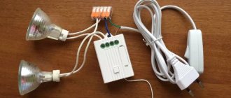
Also, a pulse relay can be useful when replacing or upgrading lamps. For example, you decide to replace the chandelier. We bought a new one, big, beautiful, and... two-section, which allows you to turn on both part of the lamps and all together. You understand that this is great, but you already have a single-key switch installed for the chandelier, and a two-wire cable is laid in the wall.
What to do? Stalemate?
No! The BIS-404 pulse relay will help you, an installation example of which [05:21] is shown in detail in this video.
Principle of operation
Standard circuits use pass-through switches, which are easy to use but require a lot of cables.
To be convinced of this, just look at the connection diagrams for pass-through switches for controlling light from two and four places.
Pulse relays allow you to optimize 220 Volt lighting networks and simplify the lighting circuit.
To ensure their operation, non-latching switches with a return spring are needed. Instead of return switches, pushbuttons can be used.
The principle of operation is based on the movement of contacts under the influence of an electromagnetic field that appears in the coil and ensures the retraction of the core. When a control signal is applied, voltage is applied or removed.
Unlike a controller, which requires different signals, only one command can be sent to a pulse relay.
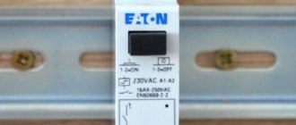
To consider the principle of operation, you can study one of the popular models - RIO-1.
The device provides the following types of inputs/outputs:
- supply of control signals (Y, Y1 and Y2) are located in the upper part of the relay;
- power contacts for supplying voltage and load - 11, 14 and N.
Each of the terminals has its own function:
- 11 and 14 - used to supply phase and load;
- Y - enable or disable when a phase is supplied, depending on the current state;
- Y1 - switching on, closing the contact group when voltage is applied (has priority over Y);
- Y2 - shutdown when a signal is supplied, is a priority signal in comparison with other inputs;
- N - supply of the 0th wire.
The closure of the 11th and 14th contacts occurs when the phase passes through the zero point. This feature reduces the risk of current surges, thus extending the life of light bulbs and contacts.
A timing diagram comes with the device, from which you can see the principle of operation.
For convenience, it is divided into four sections.
1st:
- Signal on Y. Voltage appears on the 14th output, the lamp turns on.
- Repeated signal on Y. Removing the potential and turning off the light bulb.
2nd and 3rd:
- Applying a pulse to Y1 - voltage appears on the 14th, turning on the lamp.
- The signal on Y2 means turning off the voltage at the 14th input, turning off the light bulb.
4th:
- Pulse on Y - potential on the 14th terminal, lighting the light bulb.
- The signal on Y2 is to turn off the lamp.
The presence of several such sections allows you to save money on wires and the purchase of pass-through switches.
For example, to control a lamp from several points, you need to install two or more pass-through switches, and the number of wires will be three or more. In the case of a pulse relay, one 2-core cable of 0.5 mm is sufficient.
Pulse relay. Device, principle of operation, connection diagrams
Impulse relay or crossover switch
A control circuit from three or more places can also be organized using two pass-through devices and several (according to the number of required posts) cross devices.
Laying cables when using pass-through and crossover switches using a junction box.
The cable routing in this case looks like this (PE conductor not shown). Obviously, in this case, all switches are connected to each other by a cable of three wires versus two.
Laying cables in a loop when using pass-through and crossover switches.
You can do without a junction box and make connections using a cable. In this case, taking into account the protective conductor, the number of conductors in the communication cables increases to 4. Another disadvantage of this installation is that the N and PE conductors have many connection points, which reduces the reliability and safety of the circuit.
Therefore, a circuit with a pulse relay is more economically advantageous, although it is not very common. And the greater the distance between the switches, the greater the benefit. In addition, the full load current of the consumers passes through the pass-through switch, and when the circuit is implemented on impulse devices, only a small control current is switched - the durability of the buttons will be clearly higher. When designing a lighting system, you need to pay attention to this option.
Impulse relays with built-in timer
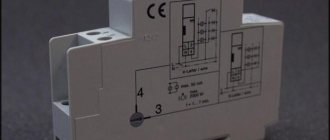
During installation, another type of pulse relay is increasingly being used, but with a timer - RIO-2.
The device works with push-button switches, has a memory function, power supply indication and load switching. Can be used in conjunction with backlit switches.
Switching on is done by a button, and switching off is done by a button or command.
After the signal is given, the device counts down the time from 1 to 12 minutes, and then fires.
Connection features:
- Contact A1 and A2 on top - connection of phase and zero.
- S - contact for receiving a pulse signal from a switch without latching.
- 18, 15, 16 - contacts, where 15 and 16 are normally closed, and 18 and 15 are normally open.
When connecting, you can use a neutral or phase wire as a control contact.
The operating principle is as follows:
- Voltage is applied to A1 and A2.
- The button is pressed to send a control signal.
- Contacts 15-18 close. The light is on.
- The button is pressed again. Opening contact 15-18 and closing 15-16. The same effect is caused by removing the supply voltage from contacts A1 and A2.
It is possible to connect up to tens of buttons, which allows you to control lighting of any degree of complexity.
Post navigation
The quality and range of illumination of the roadway depend on this characteristic. There is no interference with standard wiring.
Defender owners often complain about malfunctions of the steering column switch.
In principle, it does not present any complexity, and it is very easy to understand. You will also need a large number of consumables, such as electrical tape, clamps, terminals, heat shrink, and corrugation. The video in this article will provide additional information on the topic.
The most common cause of failure is burning of the contacts of the steering column switch, and sometimes melting of the insulator housing. In other words, when installing fog lights on a car, you need to take into account all the requirements regarding the placement and connection of fog lights. The circuit includes 30, 85, 86 and 87 contacts. I did not see the need to install 4 relays, 2 for each headlight, and limited myself to one relay for the low and high beam.
Connection diagrams
A pulse relay is used in circuits when the light is turned off from several points, for example, on the stairs, in different parts of the bedroom, dining room or other rooms.
Let's look at the basic connection diagram:
- The phase from the machine goes to the 11th contact of the relay and push-button switches without fixing (the quantity may vary).
- Contact Y receives a control signal from the other side of the transfer switches.
- The potential from the 14th contact goes to the light bulb, and from it to the “neutral” bus with contacts and to the N pulse relay.
In another scheme, two groups of devices are already used - two switches, two pulse relays, two pairs of push-button switches with return and two pairs of groups of light bulbs.
The convenience of this scheme is that with the help of one switch you can turn off the lights in the entire apartment.
In combination with a motion sensor, it is possible to provide switching on/off when the appropriate control signal is supplied.
Connection options for a pulse relay may depend on the type, so detailed recommendations should be found in the manufacturer’s operating instructions.
Pulse relay. Controlling lighting in a house and apartment. Bistable light relay. Scheme
Schematic diagram.
Purpose, operating principle and application
A classic pulse relay, like a regular one, consists of a coil with a core, a moving system and a contact group. Such a device is often called bistable - because it has two stable states: with the contacts turned off and with the contacts on. The relay state is maintained when the voltage is removed, and this is the main difference from the traditional system.
Bistable electromagnetic relay.
In real designs, the prolonged presence of voltage on the coil is considered unnecessary and even harmful - the winding may overheat. Therefore, such a device is controlled by short pulses:
- the first pulse closes the contacts;
- the second opens;
- the third closes again and so on.
Each impulse throws the contacts into the opposite state. Pulses are generated by switches. It is logical to make the switching device in the form of a button without locking in the pressed position.
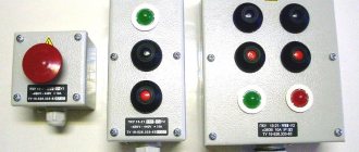
Push-button switches.
An ordinary keyboard device is of little use here - it is easy to forget it in the on position, and after a while the coil will fail. Instead of switches, you can use buttons for doorbells .
Designation on the diagram and diagram of the device operation.
A typical relay has inputs:
- A1 and A2 – for connecting 220 volt power;
- S – control input;
- NO, C, NC – contact system terminals.
There is no single standard for the designation of terminals. Input markings may vary from manufacturer to manufacturer.
In fact, the switching does not occur synchronously by pressing a button - the system waits for the nearest transition of the sinusoid through the zero value. This is done so that the switching current is zero, which extends the life of the contact group. But such a transition occurs twice per period, the maximum delay is 0.01 seconds, so the short pause is unnoticeable.
Many pulse relays for controlling electric lighting have additional on and off inputs. They have priority over the S input - when voltage is applied to them, you can force the relay to turn on or off, regardless of the state at the S terminal.
A pulse switch can be used to create lighting control systems in which lights can be turned on and off from several places, independently of other switching devices. Classically, such circuits are built on pass-through and crossover switches, but the use of pulse switching devices has its advantages.
Pulse sectional relay
The peculiarity of such devices is that using one button you can turn on different groups of light bulbs one by one or all at once.
For example, to control a chandelier with a large number of lamps, two wires are enough. In this case, you do not have to lay wiring to the device to the switch.
The device contains a connection diagram indicating two buttons and, accordingly, the possibility of control from two different points.
Let's look at the actions for each click:
- The first is to turn on the 1st group of light bulbs.
- The second is to supply voltage to the 2nd group of lamps and turn off the 1st.
- The third is to keep the second group on and add the 1st group to it (turning on all the lights).
- Fourth, turn off all the lights.
What is needed to connect headlights
First you need to prepare everything you need. Usually the same set is used:
- New headlights with fasteners so that they can be placed on the car when connected and securely fixed.
- Relay for connecting light. The easiest way is to use the standard four-pin version with connectors numbered 85, 86, 87 and 30. They are sold in car dealerships and are used for fog lights, and for any other light sources.
Basic elements for connecting light. - A fuse in a special housing for installation near the battery, rated at 15 A (or more, depending on the characteristics of the equipment).
- Button to turn the light on and off. Either a standard version is used, or an additional one, which must be installed in a suitable place in the car interior.
- Wires in the required quantity are sold in stores. The cross section will be told to you based on which headlights will be connected.
- You will also need connectors, heat shrink, screwdrivers and other tools.
The fuse can also be placed in the standard fuse box; there is usually free space there. But this will complicate the work, since you will have to pull the wiring to the block separately.
Important Tips
Before purchasing and installing a pulse relay, consider a number of points that will be useful when operating such equipment:
- If possible, choose a relay with a timer. The presence of such an option will be useful when organizing lighting indoors and outdoors.
- When installing an illuminated switch, check with the seller whether the relay can work with such elements. In some devices, the presence of a resistor may cause false operation or damage.
- If there are kids at home, it is better to raise the power button to a higher height. Otherwise, children may play with the button and press it for a long time, which may cause damage.
- During installation, all current-carrying elements should be insulated using heat shrink or PVC.
- When installing several pulse relays, it is advisable to choose devices with centralized control. They can be forcibly turned off by applying electric current to any contact.
- To save money, you can remake existing switches by installing small springs under the buttons.
Circuit operating modes
The ignition and headlights are turned off - transistors VT4 and VT1 are closed.
The ignition is on. Transistor VT1 is opened by a signal through resistor R1 and diode VD1. Through it, capacitor C1 is charged through the circuit of resistor R4, diode VD3 and cold headlight lamps. Through resistor R2 and diode VD2, voltage is applied to transistor VT2 to open it, and a signal to turn on the ignition is sent to the PB4 input of the microcontroller. The controller goes into anticipation of turning on the low beam headlights.
The low beam headlights turn on. Transistor VT3 is opened by a signal through resistor R9 and the microcontroller at the PB3 input receives a signal to turn on the headlights. The controller turns on the power transistor VT4, which lights the lamps. Due to PWM, their smooth heating is ensured within 10–12 seconds. The circuit switches to power supply via the VD4 and R6 circuit.
The low beam turns off. Resistor R10 closes transistor VT3, and the microcontroller, having received a signal at the PB3 input, turns on the PWM mode for 50% heating of the lamps. Capacitor C1, periodically recharged through diode VD3 and headlights at the moments when transistor VT4 switches, keeps VT1 open during this time.
The ignition is turned off. Through resistor R5, transistor VT2 is turned off. The signal at the PB4 input causes the microcontroller to close transistor VT4 and enter standby mode. Resistor R3 ensures the closure of transistor VT1, which de-energizes capacitor C1. The headlights turn off. The ignition is turned off with the low beam switch on. Transistors VT1 and VT4 in the closed state ensure that the headlights are turned off. Current leakage occurs only through R9, R10 within 1.7 mA, which does not significantly affect the battery discharge.
Pros and cons of pulse relay
The popularity of pulse relays is due to the following advantages:
- Low price due to more affordable components.
- Load control with voltage up to 0.4 kV.
- No influence of overvoltage, interference and powerful electrical installations.
- Reinforced insulation between contacts and coil.
- No problems with cooling.
- Harmless to the atmosphere.
- Long lasting resource.
- Possibility of using a large number of switches.
- Low power consumption.
- Simple installation compared to main switches.
Flaws:
- Long response time.
- The appearance of radio interference when turning on / off.
- Accelerated wear of moving parts.
- Creating electrical interference.
- Loud noise during operation.
Algorithms for the operation of the circuit
Slow heating when first turned on
The following happens:
• first 3 sec. The glow of the lamps gradually increases up to 30% due to PWM operation; • level of heat achieved 2 sec. maintained unchanged to warm up the lamps; • in the next 3 sec. smoothly increases to the level of 80% and the headlights provide a satisfactory level of illumination; • for the last 4 seconds. 100% power is achieved
Results
A pulse relay is an alternative to pass-through switches, allowing you to save on wire/equipment and expand the ability to create complex lighting circuits.
Depending on the situation, you can choose conventional models or devices with a timer that provide a time delay before operation.
Pulse relay. Connection diagram. Lighting control from multiple locations.
How to install and connect with your own hands?
Installing fog lights on your own begins with developing a connection diagram. A properly designed circuit avoids unnecessary wires and ensures reliable operation of the electrical circuit. It is recommended to carry out installation work in the garage, although many owners install it outdoors.
Installing PTF in the front bumper and setting it up
The setup is done using the homemade template presented below. The template is installed perpendicularly at a distance of 5 m from the car headlights. The adjustment is made until the top edge of the light spot coincides. The matching line is located 100 mm below the height of the center of the lamps.
Approximate view of the template for customization
Adjusting your fog lights increases driver visibility and reduces the risk of blinding oncoming drivers.
Installing PTF in a blind bumper
The most difficult and time-consuming option is to install fog lights in a solid bumper (i.e., one that does not have factory holes for this):
- Remove the bumper from the vehicle in accordance with the repair and operating instructions.
- Determine the optimal location for installing headlights in terms of housing shape and compliance with regulations.
- Make a hole for the headlights. The best way is to drill holes around the perimeter and saw through the gaps with a file. The hole must be adjusted to ensure proper fit between the body and the decorative frame. Small fragments of the bumper are carefully cut off with a construction or stationery knife.
- Drill holes for the fog lamp housing, which is secured with suitable bolts.
- Install the headlight into the housing and mount the protective cover. It clings to the plastic of the bumper.
- You can adjust the headlight using a special key included in the kit.
Installing PTF on the external bracket
Option for mounting foglights on a steel bracket:
New relays with the letter "i"
Impulse relays appeared in the Euroautomatika FiF catalog, with the letter i added to their names. At the same time, the names themselves are duplicated.
For example:
- BIS-411 - BIS-411i
- BIS-412 - BIS-412i
- BIS-413 - BIS-413i
Externally they are no different, but relays with the letter i are more expensive.
The price difference ranges from 50 to 400 rubles, depending on the model.
The obvious question is, “Why pay more?”
The fact is that the built-in contacts of the new relays can briefly withstand currents of up to 125 Amps. True, for only 20 milliseconds, but this will be enough to use the relay to turn on powerful incandescent lamps, electric motors, solenoid valves and other equipment with increased starting current.
Now the question is: How is this implemented in practice? I opened a couple of BIS-412s, an old and a new impulse relay, and this is what I saw.
Pulse relay device BIS-412i
The new LSIs contain HONGFA INRUSH series electromagnetic relays, which are specifically designed to withstand high inrush currents typical of reactive or capacitive loads.
The relay also uses a more powerful microcontroller and voltage converter, thanks to which the relay operates from both direct and alternating voltage, from 100 to 260 Volts.
Advantages
It turns out we pay more for:
- Starting current up to 125 A (20ms)
- Possibility to operate from AC/DC 100 - 256 V due to the built-in converter.
- And in the case of BIS-412i - a simplified group connection diagram.
Today you can choose between old and new relays, although soon the plant may completely switch to new models, with the letter “i”.
CS-CS.Net: Laboratory of the Electroshaman
This post was written in response to numerous requests from people who consult with me and for whom I collect shields. It turns out that the most difficult thing is to explain how to connect the buttons in the socket boxes to these relays using one cable cable and use everything. Now I will do a small educational program on the topic of how to connect impulse relays and how to do the wiring for them.
First, let's recall the old posts and briefly all the material:
- ATTENTION! Since the fall of 2015, impulse relays of the E250 series (E251, E257 C) have been discontinued. Instead, you need to use the New E290 series impulse relays. Read a new post about them with a review and a link to the catalog.
- Tricky information. It turns out that you don’t have to buy buttons for impulse relays. It is enough to make (or find suitable) springs for them. I wrote a separate post about this: .
- I also wrote a very large post about BUTTONS for pulse relays and the technology of their use. Read it!
- A pulse relay is such a clever thing that allows you to control lighting using buttons without pass-through switches: press the button and the light turns on. Pressed it again and it turned off. The benefit here is that all control buttons are connected in parallel to one line and there can be an infinite number of them.
- Such relays come with central control: for example, all relays can be turned off at once, turning off all the lights in the apartment.
- These relays are either electronic or electromechanical. Electronic ones are produced by good ones (the same one that produces UZM-51m), and electromechanical ones are made by my evil ABB. Attention! At the moment (of writing this post) ABB has a slight delay in supplying relays, and they are marked (temporarily!) as discontinued to prevent people from ordering them. In one or two months the situation will improve, and the relay can be ordered again!
- To control these relays, you can lay cables on a large number of cores (KVVG and MKSh cables) and you can make double control buttons - two buttons in one socket, which saves space.
And now let’s get back to the very damn basics, which I considered so simple that I skipped them. So - how to connect and use a pulse relay?
Let's remember what he has from contacts:
- A1-A2 . These are the relay coil contacts. The coil can have a supply voltage of 12, 24 volts or 220 volts. Most often, for ordinary tasks, a 220-volt coil is convenient for us, because we still have a power panel, and it’s easier to carry all the control circuits with the same mains voltage. In electromechanical relays, if you briefly ( pulsely - hence the name of the relay) apply operating voltage, the relay will change its state to the opposite. In electronic relays, power must be supplied here for the entire time the relay is operating.
- 1-2 (or other numbering). This is the contact or contacts that close or open when the relay operates. It is important to understand that these are JUST CONTACTS. There will be no voltage on them and there will be no “input” or “output” of any kind. The relay simply has contacts with which we ourselves must close the power circuit of the light bulb (or some other load) in the panel.
- ON, OFF - for relays with central control. These are contacts that force the impulse relay to turn off or on. The supply voltage is usually supplied to them between one of the coil contacts (most often A2) and this contact. That is, for ABB, to turn off the relay, you need to supply 220 volts between OFF-A2 .
So, the simplest scheme in words will be like this. Let's supply the power phase to the button(s), which will switch the relay. We will apply the same phase to contact “1” so that it goes through the relay to power the light bulb. From the button we send a control signal to contact A1 of the relay coil. And we will apply zero to the light bulb and to contact A2 of the relay. This is what we get:
Pulse relay connection diagram
Here we use good and competent cheating, which is associated with caring for people. Here, by installing a machine for this group of lights at the beginning of the entire circuit, we solved several problems at once: protecting the relay coil. Protection of control circuits. And lamp protection. And also the protection of the brain of a person who will know: if you turn off the machine, no relay will click.
Switchboard structure with impulse relays
We can set up as many control buttons for this relay as we like. Now let’s immediately talk about how we can competently and logically distribute our pulse relays in the shield. According to some schemes that I saw on MasterCity.Ru, people there do not understand the structure and mess up.
So, our structure consists of the following levels:
- Protection of a light circuit breaker (RCD) for several light circuit breakers. Let’s say we have an RCD “Light first floor”, and under it there are machines “Light Hall”, “Light Living Room”, “Light Dining Room”. Everything is clear here - this is how we assemble the shields. In the case of dif-automatic machines, it is also clear: we do not put anything before the diffs, but we equate the diffs themselves with automatic machines and consider them below:
- Light group protection circuit breaker. It protects the power cables of the lamps. And in the case of using pulse relays - control cables. This machine is selected and installed in the same way as in the case of designing a conventional panel. If we need to put a machine in the room with a light set to 6A, we’ll set it up. We need it at 10A - set it.
- Pulse relays. But here it is already interesting and at the same time simple: for each group of light we install our own relay. If we take the circuit without pulse relays, then we will have two switch keys: Top light and Sconce light. We put a pulse relay on each such key so that different types of light can be turned on and off separately. But if we turn on several types of light simultaneously with one key, then we will need one relay. In general, one switch “key” is one relay.
I depicted this structure in the figure to make it clear. In the Hall from the example, we have three groups of light (say, ceiling, floor lighting and sconces). In the Living Room there are two groups (a chandelier made of two groups of lamps), and in the Dining Room there is one group of light - a lamp from above.
Structure (diagram) of a panel on pulse relays
Do you see? So far everything is simple. And very important. That is, first we “assemble” a regular shield, which ends with automatic devices for light. And on these machines we attach as many pulse relays as needed.
Well? Let's draw this structure for an example of three groups? Here, look at the diagram:
Diagram of a panel with pulse relays for three groups of light
Here the power phase from the machine went to the buttons and to contacts “1” of all relays. Here we can use jumpers because all three relays are powered from the same circuit breaker. That is, there is no need to think with your head - we power all the relays in a row. We apply zero to the lamps and to contacts “A2” of the relay. The “output” of the phase from the relay is to the lamps of the desired group. And the signal from the buttons goes to A1 of the required relays. All!
And we’ll immediately make an indent about installing this in the panel! Sorry, there won't be any photos, I'll describe it in words. It is very important to understand that on paper everything is so beautiful and simply connected. But in reality you will end up with several different connections and cables. At one point you will need to connect the PuGV, with which you assemble the shield, and the VVG, which came from the lamps or buttons. Well, let's describe the cables that will come from the panel:
- Cable for buttons . ONE cable for ALL buttons of this machine. Look carefully at the diagram. All buttons have one common wire - phase. This will be one cable core. Next we need PE to protect our cable. This is the second core of the cable. And we also need as many wires in the cable as there are impulse relays under its control. That is, for our example, we need a cable with 5 cores: L, PE, Relay 1, Relay 2, Relay 3. But we pull this cable with a cable from one place where the buttons will be located to the second. From the second to the third and so on - as with sockets. This was just written about in the post about cables for buttons and controls.
- Cables for lamps . Since what turns on the lamps is now located in the panel on a DIN rail, the cables that go to the lamps also extend from the panel. From each relay there is one cable per group of lamps. Here we do what we are used to: we consider that our relay is a light switch. This is how we would route the cables if this switch is in the room - that’s what we do. Usually one cable is enough, and then it is routed directly to the lamps as a cable. In our example, there will be three cables - we have three relays.
And here I STRONGLY recommend using TERMINALS in the panel to connect these cables! This makes it VERY simple to assemble the shield and connect the cables. Because from the point of view of cables, it turns out that one cable core is connected strictly into one “hole” of the terminal. And from the point of view of the shield, you can connect everything you need with PuGV wire using NShVI(2) lugs.
Here's a look at how installing a panel without terminals and with terminals will look like:
- Without terminals . Phase 220 went to pulse relays from the machine. Then, under the same machine or under the relay contact, you need to slip the cable from the buttons. It turns out that this needs to be marked somehow on the dashboard. And tear the cable cores all over the shield: one for the machine, the other for the relay. Wires from the same button cable went to impulse relays. Well, let's say it rolls. But again, for those who will connect the shield, it will not be very convenient to insert the cable cores among the installation of the shield. The same goes for the phase wires of light bulbs. The neutral wires from the light bulbs and from the relay coils need to be connected somewhere... where? Provide a zero bus for each machine? So what for?
- With terminals . The phase from the machine went to the relay. From there she went to the terminals. Zero went to the terminals, then to the relay. And all that remains is to stupidly connect the terminals of the buttons and the relay coils, and the terminals of the lamp phases and the “output” contacts of the relay. All! And then tie it together with zip ties, put it in a punched box, etc. as desired.
So I beg you: love yourself and your work. Use terminals!
Centrally controlled relay
Let's go a little deeper into the wonderful world of automation, hehe. Let's consider impulse relays with central control . As I already wrote, these relays allow themselves to be turned off in a bunch. That is, it is convenient to turn off all the lights in the apartment. I’m showing the diagram right away, because I had it in my archives and there were good explanations:
Connection diagram for a pulse relay with central control
So, in the usual control version, a centrally controlled relay is no different from a conventional relay. Therefore, all the rules for arranging relays into groups and installation are absolutely the same as in the normal case. But with the central switching off and on there will be some confusion. Well, who is the most attentive here? Who will guess first?
The essence of the trap is this. To turn off all pulse relays, you need to apply the power phase to all their “OFF” contacts. What is our first reaction? Elementary: we connect all the contacts with a jumper in a row and feed... and WHAT do we feed? After all, we have different impulse relays powered by different machines. And if the shield is three-phase, then it also comes from different phases... And we cannot connect all the “OFF” contacts in a row. Otherwise, either the RCD will trip, or the interphase 380 will fly to the winding coils.
In the catalog for pulse relays there are some group modules that seem to be designed to separate control signals. But the catalog doesn’t say whether they share meals. And the diagram is given for one phase for all relay groups. And these modules are on order for 8 weeks.
We make reliable decisions, right? And we do them brutally? Yeah. Reliable and brutal. What else can give us good galvanic isolation? In! Ordinary RELAY! Intermediate, for example. I once did a short review of them on the CR-P series. Then we can assemble a circuit for resetting all the relays under different machines and phases in this way:
Centrally Controlled Relay Reset Circuit
The entire control thing (buttons and relay reset) revolves around the machine from which these relays are powered. That is, through the contacts of the reset relay, the same phase from the same machine is supplied to the OFF contacts of the same relays. Hooray! But we will power the coils of all reset relays from the “Turn everything off” button from some separate machine. Or from the corridor light machine, where this button is usually located. And since the CR-P relay series has a relay with two groups of contacts, one CR-P relay will reset up to two circuit breakers for these relays.
I constantly use this solution in my shields, and it is the most reliable and has been tested for years. When I came up with it, I decided not to worry and not look for others. However, practice and various interesting problems forced me to reconsider the concepts. And I came up with and am using another solution.
I transfer ALL control circuits throughout the apartment to a separate machine in the panel. Remember, in our pulse relay the coil and the load contacts are not connected in any way. Therefore, we can control all the relays using one power supply (and even almost 24 volts), and with their contacts we can switch regular power from the lighting circuit breakers to the lamps.
In this case, we don’t need intermediate reset relays. We save money and modules in the panel and even make a profit in the case of ABB electromechanical relays. They have a lever for manually turning on the relay. This means we can turn on the light in the room, turn off the control circuits and, in the light, tinker with the buttons, connecting them. And this also benefits us!
Wiring and connecting the control button cable to the buttons
And now - metaphysics. Kidding. But for some reason this simple topic causes stupor and brain explosion for many. I will try to give general principles and somehow explain it. I'm talking about how we can lay the cable for the control buttons and connect it to these same buttons. Let's take a look at what we have:
- Button cable (relay control) . We have one common phase conductor and several conductors there - one for each relay. If you close these wires with a phase wire, then the corresponding relays will click. The cable is connected to the terminals in the panel and we are not interested in it there now.
- Different places on the wall where these buttons should be . Agree, since we have invested money in impulse relays, it is stupid to make their control buttons in only one place in the room. Throw these buttons everywhere: by the window, by the sofa, by the table!
And now attention, complexity! Get it into your head that we route the control cable with a LOAD to all the places where we will have control buttons, regardless of the number of buttons. That is, if we have three buttons at the entrance to the room, and two at the sofa, then the cable goes from the panel to the entrance to the room, from the entrance to the sofa.
Why can we have more control buttons in one place and fewer in another? It depends on the design and appearance. For example, when entering a room, it’s convenient for us to control all the lights at once: you never know what we forgot to turn off. But on the sofa, the block of three buttons will be large, and you can put a double button there (one socket) and connect only the most necessary light groups to it.
Now pay attention again! Our control cable is the SAME EVERYWHERE! That is, in ANY place where this cable passes, we have the opportunity to control ANY relay - we just need to connect the desired core of this cable to the button, which is responsible for this relay.
This can give us the following benefit: if someday we decide that it is more convenient to control the backlight from the sofa rather than the overhead light, then we just need to re-wire the control cable wires. That's all. There is no need to reconnect anything in the panel or anywhere else! And we can, for example, having 5 control groups, put blocks of 4 buttons everywhere in the room. And in different corners of the room, control different groups of light in a way that is more convenient for us.
And now in simple words: the control cable is routed through all the places where there will be control buttons for this light. Here you have a living room light control cable. Wherever you need living room light control buttons (even in the hall in front of it) - you lay this “Living Room Light Buttons” cable as a cable. Since the cable always contains all the light control wires, if we don’t like something, we can change the purpose of the button simply by changing the wires that it closes.
And now I will show you how to mount our buttons in socket boxes. For those who haven’t read it, I remind you of the post about installation in socket boxes and strongly advise you to refresh your memory. We will need three-dimensional thinking and some WAGO terminals for two “holes”. Then we remember that any button usually has two holes for each contact, like sockets, so that the buttons can be connected with a cable. And this is where everything falls into place.
Our connection concept will be this: the control phase (there is almost never a load on it, except for the relay coils that are connected when the buttons are pressed) we connect with a cable through all the buttons of the socket box. And we send it further to the next cable and button block. We connect the control wires that we use with a cable directly to the buttons. And we connect the PE and the cores not used in this block together through WAGO. We get this miracle:
Installation diagram of impulse relay control buttons
So how? Is everything simple and clear? And if we now need to change the purpose of the button, then we will pull out the unnecessary wires from it. Let's connect them WAGO so as not to break the chain. And in their place we will insert other wires that were previously connected by WAGO. Profit!
Different connection schemes
I took these diagrams out of my shield in 19″ format with automation for Cthulhulización. Here you can see how I assigned the cores of the control cables and loads. I also put a power supply in the cables, just in case: would it be necessary to light up and connect something in the same socket?
Example of circuits with pulse relays (sheet 1)
This is a diagram of a block of 5 buttons for three relay groups: turn on all groups, control groups separately and turn off all groups at once.
Example of circuits with pulse relays (sheet 2)
And this is a diagram of a block in which all relays are turned off after the presence sensor is triggered.
Example of circuits with pulse relays (sheet 3)
I will give a description from my document:
Relays E257 have the following control contacts: A1, A2*, ON, OFF. When different signals are supplied, pin A2* is common to them. When voltage is applied between contacts A1-A2*, the relay changes its position (on/off) to the opposite. When voltage is applied to contacts A2*-ON, the relay is forcibly turned on, and when voltage is applied to contacts A2*-OFF, it is turned off.
CT-MFD time relays are used in the mode of generating a rectangular pulse based on the decline of the control signal (power phase) at contact Y1. When a phase is applied to Y1, nothing happens (a pulse will be generated only when the phase on Y1 is lost). With its contacts, the relay briefly (for a pulse duration of 0.5-1 sec) closes the OFF circuit of all E257 relays.
The motion sensor supplies the phase simultaneously to the power supply of the LED-Lamp circuit and to the control contact Y1 of the CT-MFD time relay. When the motion sensor finishes powering the backlight (the operating interval is set in the sensor), the phase from it will disappear on contact Y1 of the CT-MFD relay. This will generate a pulse that will turn off all E257 impulse relays, turning off the lights completely (equivalent to manually pressing the All Off button).
This is such a system - these pulse relays! If you have any questions, ask in the comments!