Every radio amateur has encountered the NE555 chip more than once. This little eight-legged timer has gained enormous popularity for its functionality, practicality and ease of use. On the 555 timer, you can assemble circuits of various levels of complexity: from a simple Schmitt trigger, with just a couple of elements, to a multi-stage combination lock using a large number of additional components.
In this article, we will take a closer look at the NE555 microcircuit, which, despite its advanced age, is still in demand. It is worth noting that this demand is primarily due to the use of ICs in circuitry using LEDs.
Description and scope
NE555 is the development of the American company Signetics, whose specialists did not give up during the economic crisis and were able to bring to life the works of Hans Camenzind. It was he who, in 1970, managed to prove the importance of his invention, which at that time had no analogues. The NE555 IC had a high installation density at low cost, which earned it a special status.
Subsequently, competing manufacturers from around the world began to copy it. This is how the domestic KR1006VI1 appeared, which remained unique in this family. The fact is that in KR1006VI1 the stop input (6) has priority over the start input (2). Imported analogues from other companies do not have this feature. This fact should be taken into account when developing circuits with active use of two inputs.
However, in most cases, priorities do not affect the operation of the device. In order to reduce power consumption, back in the 70s of the last century, the production of a CMOS series timer was launched. In Russia, the field-effect transistor microcircuit was named KR1441VI1.
The 555 timer has found its greatest application in the construction of generator circuits and time relays with the possibility of delays from microseconds to several hours. In more complex devices, it performs the functions of eliminating contact bounce, PWM, digital signal restoration, and so on.
Features and Disadvantages
A special feature of the timer is an internal voltage divider, which sets a fixed upper and lower threshold for two comparators. Since the voltage divider cannot be eliminated and the threshold voltage cannot be controlled, the application area of NE555 is narrowed.
The timer on bipolar transistors has one significant drawback associated with the transition of the output stage from one state to the opposite. Each switching is accompanied by a parasitic through current, which at its peak can reach 400 mA, increasing thermal losses. The solution to the problem is to install a polar capacitor with a capacity of up to 0.1 µF between the control pin (5) and the common wire. Thanks to it, stability at startup and reliability of the entire device increases. In addition, to increase noise immunity, the power circuit is supplemented with a 1 µF non-polar capacitor.
Timers assembled on CMOS transistors do not have these disadvantages and do not require the installation of external capacitors.
DIY time relay on a 555 timer
08/31/2012 Electronic equipment
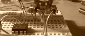
In the video tutorial of the channel “homemade products and reviews of packages from jakson” we will assemble a time relay circuit based on a timer chip on NE555. Very simple - few details, it will be very easy to solder everything with your own hands. Along with this, many will need it.
Radio components for time relays
The microcircuit itself, two simple resistors (one variable, one polar), a 3 microfarad capacitor, a 0.01 µF non-polar capacitor, a KT315 transistor, almost any diode, one relay will be useful. The device supply voltage will be from 9 to 14 volts. You can purchase radio components or a ready-made time relay in this Chinese store.
A plugin for Google Chrome to save money: 7 percent of purchases are returned to you.
The scheme is very simple.
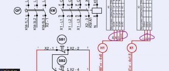
Time relay circuit on a 555 timer
Anyone can master it, given the necessary details. Assembly on a printed circuit board, which makes everything compact. As a result, part of the board will need to be broken off. A simple button without a lock will come in handy; it will activate the relay.
In addition, there are two variable resistors, instead of one, which is required in the circuit, because the master does not have the required value.
2 megaohms. Two 1 megaohm resistors in series. In addition to this relay, the supply voltage is 12 volts DC, and can pass through itself 250 volts, 10 amperes alternating current.
Upon completion of assembly, this is what a time relay based on a 555 timer looks like.
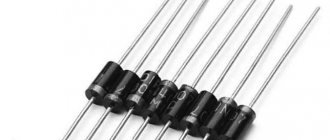
Everything turned out to be compact. The only thing that visually spoils the appearance is the diode, because it has such a shape that it is impossible to solder it otherwise, because its legs are much wider than the holes in the board. It still turned out to be good enough.
Checking the device on a 555 timer
Let's make sure the domestic relay is reliable. The operation indicator will be an LED strip. Let's also connect a multimeter. Let's make sure it's reliable - press the button, the LED strip lights up. The voltage supplied to the relay is 12.5 volts. The voltage is currently zero, but for some reason the LEDs are on - probably a relay malfunction.
It is old, soldered from an unnecessary board.
By transforming the position of the trimming resistors, we can adjust the operating time of the relay. Let's measure the large and minimal time. It turns off almost immediately. And big time.
About 2-3 minutes passed. - you can see for yourself.
But such indicators are only in the presented case. Yours may be different, because it depends on the variable resistor that you will use and on the capacitance of the electric capacitor. The larger the capacity, the longer your time relay will work.
Main parameters of the 555 series IC
The NE555 internals includes five functional units, which can be seen in the logic diagram.
At the input there is a resistive voltage divider, which generates two reference voltages for precision comparators. The output contacts of the comparators go to the next block - an RS flip-flop with an external reset pin, and then to a power amplifier. The last node is an open collector transistor, which can perform several functions, depending on the task at hand.
The recommended supply voltage for IC types NA, NE, SA is in the range from 4.5 to 16 volts, and for SE it can reach 18V. In this case, the current consumption at minimum Upit is 2–5 mA, at maximum Upit – 10–15 mA. Some 555 CMOS series ICs consume less than 1 mA. The highest output current of an imported microcircuit can reach a value of 200 mA. For KR1006VI1 it is not higher than 100 mA.
The build quality and manufacturer greatly influence the operating conditions of the timer. For example, the operating temperature range of NE555 is from 0 to 70°C, and SE555 from -55 to +125°C, which is important to know when designing devices for operation in open environments. You can get acquainted with the electrical parameters in more detail and find out the typical values of voltage and current at the CONT, RESET, THRES, and TRIG inputs in the datasheet on the XX555 series IC.
Analogues of the NE555 chip
The 555 chip, the analogue of which in Russia was called KR1006VI1, is an integrated device.
View gallery
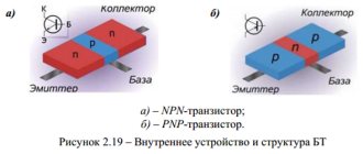
Among the working blocks, we should highlight the RS trigger (DD1), comparators (DA1 and DA2), an output amplifier stage based on a push-pull system and a complementary transistor VT3. The purpose of the latter is to reset the time-setting capacitor when using the unit as a generator. The trigger is reset when a logical unit (Jupit/2...Jupit) is applied to the R inputs.
If the trigger is reset, a low voltage reading will be observed at the device output (pin 3) (transistor VT2 is open).
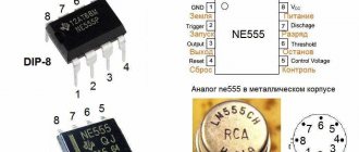
Location and assignment of pins
The NE555 and its analogs are primarily available in eight-pin PDIP8, TSSOP, or SOIC packages. The pinout arrangement, regardless of the housing, is standard. The symbolic graphic designation of the timer is a rectangle with the inscription G1 (for a single pulse generator) and GN (for multivibrators).
- General (GND). The first conclusion is regarding the key. Connects to the negative power supply of the device.
- Trigger (TRIG). Applying a low-level pulse to the input of the second comparator leads to the launch and appearance at the output of a high-level signal, the duration of which depends on the rating of the external elements R and C. Possible variations of the input signal are written in the “Montistrator” section.
- Output (OUT). The high level of the output signal is (Upit-1.5V), and the low level is about 0.25V. Switching takes about 0.1 µs.
- Reset (RESET). This input has the highest priority and is able to control the operation of the timer regardless of the voltage on the other pins. To allow startup, it is necessary that a potential of more than 0.7 volts be present on it. For this reason, it is connected through a resistor to the power supply of the circuit. The appearance of a pulse of less than 0.7 volts prohibits the operation of NE555.
- Control (CTRL). As can be seen from the internal structure of the IC, it is directly connected to the voltage divider and, in the absence of external influence, produces 2/3 Upit. By applying a control signal to CTRL, a modulated signal can be obtained at the output. In simple circuits it is connected to an external capacitor.
- Stop (THR). It is the input of the first comparator, the appearance of a voltage on which exceeds 2/3 Upit stops the operation of the trigger and turns the timer output to a low level. In this case, there should be no trigger signal at pin 2, since TRIG has priority over THR (except for KR1006VI1).
- Discharge (DIS). Connected directly to the internal transistor, which is connected according to a common collector circuit. Typically, a timing capacitor is connected to the collector-emitter junction, which discharges while the transistor is in the open state. Less commonly used to increase the load capacity of the timer.
- Power (VCC). Connects to the positive of a 4.5–16V power source.
Ne555 connection diagrams
In itself, this microcircuit is like an “unfinished” product with the ability to implement two operating modes on it - a start timer (monostable) and a single pulse generator (multivibrator). To make it function in one of them, a little modification is needed. To do this, an RC circuit (also a timing circuit) is added between pins 1 and 8, for which a resistor and capacitor are selected in advance. Their values will set the required frequency and periodicity of rectangular “on/off” signals at the output of the microcircuit after power is applied to it. To increase the accuracy of operation and avoid the influence of external interference, it is recommended to shunt 5 pins (control) with a capacitance, the value of which should be no more than 0.1 µF.
Monostable mode
Let's look at the principle of operation in timer mode. To implement it, additional elements are required - one resistor Rt and a pair of capacitors. After power is applied, the third leg relative to ground will be about 0V. The timing capacitor Ct is completely discharged and the circuit can remain in this state for quite a long time until a positive signal is received at pin 2 (start). Its value should be three times less than the supply voltage (Ucc/3).
After a signal is applied to pin 2 (start), a voltage similar to the supply voltage appears at the output of the microcircuit (high level). Its duration depends on the charging time Ct to a level of 2/3 of Ucc through resistor Rt. As soon as this happens, the output voltage will drop to almost 0V and Ct will be discharged.
The important point in this circuit is that once it is turned on, any influence on pin 2 (start) will no longer drive the output high. But it can still be reset if you apply a signal to the fourth leg (reset). The time interval of the output pulse (T) is calculated using the formula T=1.1*Rt*Ct.
Multivibrator mode
In multivibrator mode, the ne555 microcircuit produces a series of rectangular signals, the periodicity of which is also determined by the values of the timing RC chain. As you can see from the picture below, the design has been slightly modified and another resistance has been added to it. Pin 7 (bit) is physically connected between resistors Ra and Rb, but is logically disabled inside the universal timer.
After power is applied to the microcircuit, a high level relative to ground will appear on pin 3 (output), and the capacitor Ct begins to charge through Ra and Rb. As soon as Ct reaches a charge of 2/3 of the supply voltage, the circuit will switch and its output will be about 0V. In this case, contact 7 (discharge) will turn on and Ct will be discharged through resistor Rb.
After the capacitor Ct is discharged by 1/3, the circuit switches again and a high level appears at its output. Contact 7 (discharge) will be disconnected and Ct will begin to charge again through Ra and Rb. The result of such work will be a series of rectangular pulses, the duration of which will be determined by the values of the elements Ra, Rb and Ct. The interval between the beginning of each pulse is called the total TP period. It can be increased to 30 seconds by increasing the Ct capacity. The oscillation frequency is determined by the formula F = 1/TP.
NE555 Operating Modes
The 555 series timer operates in one of three modes; let’s look at them in more detail using the NE555 chip as an example.
One-shot
The circuit diagram of the single-vibrator is shown in the figure.
To form single pulses, in addition to the NE555 microcircuit, you will need a resistance and a polar capacitor. The scheme works as follows. A single low-level pulse is applied to the timer input (2), which causes the microcircuit to switch and a high signal level to appear at the output (3). The duration of the signal is calculated in seconds using the formula: t=1.1*R*C.
After a specified time (t), a low-level signal is generated at the output (initial state). By default, pin 4 is combined with pin 8, that is, it has a high potential.
When developing schemes, you need to take into account 2 nuances:
- The power supply voltage does not affect the duration of the pulses. The higher the supply voltage, the higher the charging rate of the timing capacitor and the greater the amplitude of the output signal.
- An additional pulse, which can be applied to the input after the main one, will not affect the operation of the timer until time t has expired.
The operation of the single pulse generator can be influenced externally in two ways:
- apply a low-level signal to Reset, which will return the timer to its original state;
- As long as input 2 receives a low level signal, the output will remain high.
Thus, using single signals at the input and parameters of the timing chain, it is possible to obtain rectangular-shaped pulses with a clearly defined duration at the output.
Multivibrator
A multivibrator is a generator of periodic rectangular pulses with a given amplitude, duration or frequency, depending on the task.
Its difference from a single-vibrator is that there is no external disturbance for the normal functioning of the device. The schematic diagram of a multivibrator based on NE555 is shown in the figure. Resistors R1, R2 and capacitor C1 participate in the formation of repeating pulses. Pulse time (t1), pause time (t2), period (T) and frequency (f) are calculated using the formulas below:
From these formulas it is easy to see that the pause time cannot exceed the pulse time, that is, it will not be possible to achieve a duty cycle (S=T/t1) of more than 2 units. To solve the problem, a diode is added to the circuit, the cathode of which is connected to pin 6, and the anode to pin 7.
In the datasheet for microcircuits, they often operate with the reciprocal of the duty cycle - Duty cycle (D=1/S), which is displayed as a percentage.
The scheme works as follows. At the moment of power supply, capacitor C1 is discharged, which turns the timer output into a high level state. Then C1 begins to charge, gaining capacity to the upper threshold value of 2/3 UPIT. Having reached the threshold, the IC switches, and a low signal level appears at the output. The process of discharging the capacitor (t1) begins, which continues until the lower threshold value of 1/3 UPIT. When it is reached, the reverse switching occurs and the output of the timer is set to a high signal level. As a result, the circuit goes into self-oscillating mode.
Precision Schmitt trigger with RS trigger
The NE555 timer has a two-threshold comparator and RS flip-flop built into it, allowing you to implement a precision Schmitt trigger with an RS flip-flop in hardware. The input voltage is divided by the comparator into three parts, when each of them is reached, the next switching occurs. In this case, the value of hysteresis (reverse switching) is equal to 1/3 UPIT. The ability to use NE555 as a precision trigger is in demand in the construction of automatic control systems.
Timer with delayed shutdown on Ne555
My wife and I purchased an anti-mosquito fumigator, and I thought that it was not good that it worked all night, and decided to build a timer on the well-known Ne555.
I assembled the circuit and seemed pleased with it, but I couldn’t get more than 40-50 minutes out of it, and I calmed down, seemingly thinking that this time would be enough for the procedure of killing mosquitoes, but it turned out no, I experimentally determined that at least 2.5 hours were needed (for stable introduction of mosquitoes, in a steep dive). I started studying the Ne555, or rather tinkering with the circuit in the excellent online simulator https://www.falstad.com/circuit/, and discovered that if we apply a voltage from 0 to the supply voltage to the 5th leg of the microcircuit, we can significantly influence timer operation time. Later I looked into the documentation of this wonderful microcircuit and found confirmation of this, the 5th leg was created for this purpose, to influence the timer comparator divider, that is, by applying this or that voltage to the 5th leg of the timer, we can control the shutdown interval. the first thing that came to my mind was to connect a controlled reference voltage source to the fifth leg. But in the simulator it suddenly became clear that this voltage does affect the time interval, but logarithmically, that is, up to 1 volt, it greatly increases this interval, and then with a small scatter. For my purposes, it is necessary to apply a voltage with an amplitude of 0.5 volts, and then the idea came to my mind: what if I apply it through a diode from the output of the microcircuit to the 5th leg of it, but I connected the output of the microcircuit to the anode, well, logically, that’s how it should be work, but nothing happened, that is, the time interval did not change, out of despair I turned the diode the other way around and oh eureka, I got the desired effect on the interval, it became 3.6 times longer, that is, not 40 minutes but 2 hours 20 minutes , this is in the simulator, but practice turned out to be even more generous, the timer turned off after 2 hours 40 minutes, the timer works stably. Now the mosquitoes are also dying, but we see the seller of the fumigator liquid less often, and I still have some money left in my pocket, so I’ll use this extra money to buy this miracle microcircuit. Here is a circuit with an additional diode circuit at the output.
Receive a selection of new homemade products by email. No spam, only useful ideas!
*By filling out the form you agree to the processing of personal data