- 7.1 Current amplitude
Galileo Galilei, while studying pendulums and musical strings, described a phenomenon that later became known as resonance. It manifests itself not only in acoustics, but also in mechanics, electronics, optics and astrophysics. The resonance effect has both positive and negative effects on oscillatory systems.
Resonance
Resonance effect
A striking example of the mechanical class of resonators is the spring pendulum. Professor from the Massachusetts Institute of Technology (in America), V. Levin, focuses the attention of his students on the fact that resonance is an effect associated with an increase in amplitude. An installation is used to demonstrate the phenomenon. It consists of the following components:
- electric motor;
- a mechanism that turns rotation into reciprocating motion;
- LATR – laboratory autotransformer;
- copper wire spring with a set of weights;
- spring guide.
The direction of spring oscillation is vertical. The rotation of the motor shaft causes the spring to oscillate. Using an autotransformer, it is possible to regulate the voltage. The adjustment allows you to vary the frequency of rotation of the shaft and oscillations of the pendulum. When the shaft rotation speed changes, the amplitude of the reciprocating motion remains unchanged.
Before the experiment, the elongation of the copper spring under the action of weights is measured (to estimate the resonant frequency of the spring). Changing the speed of rotation of the shaft causes the amplitude of oscillation of the end of the spring with the load to change. The amplitude increases and at the 1st hertz of frequency it becomes maximum (~30 cm).
Important! With a further increase in the shaft rotation speed, the amplitude of the end of the spring begins to decrease. This means that resonance has passed. If you reduce the voltage, and with it the engine speed, you can again observe the effect of resonance oscillations of the spring.
Spring pendulum
The quality factor of the spring Q is defined as the ratio of the oscillation amplitude of the spring Apr to the oscillation amplitude of the driving force Aavs. In this case, Q = Apr/Avs = 30/5 = 6, where Avs = 5.
Definition of an Oscillatory Circuit
Rotation frequency: formula
Resonance phenomena noted in electrical engineering are clearly expressed in the circuits of oscillatory circuits (OC). Such designs are elementary systems capable of carrying out free oscillations of an electromagnetic nature. The CC itself in the circuit consists of the following elements:
- capacitor;
- inductors;
- current source.
Attention! The terminals of the circuit elements can be connected to each other in parallel or in series. It all depends on what result you want to achieve from resonance in the CC.
Connecting to the inductive coil circuit
Resonance in an electrical circuit
The inclusion of an inductor in a capacitive circuit immediately turns it into a CC. Depending on the connection diagram, there are two types of class 1 CCs: parallel and serial.
Parallel QC
In this circuit, capacitor C is connected to coil L in parallel. If a charged capacitor is connected to a coil, the energy stored in it will be transferred to it. A current will flow through the inductive coil L, causing an electromotive force (EMF).
The self-induction emf L will be aimed at reducing the current in the parallel circuit. The current created by this EMF and the discharge current of the capacitor are initially identical, and their total value is zero. The capacitor will transfer its energy Ec to the coil and will be completely discharged. The inductance, having received the maximum magnetic energy EL, will begin to charge the capacitor with a voltage of a different polarity. When all the energy from the inductance goes into the capacitor, the capacitor will be fully charged. Oscillations appear in the circuit; such a circuit is called an oscillatory circuit.
Parallel QC
For your information. If there were no losses in such a circuit, then such oscillations would never begin to fade. In practice, the duration of the process depends on the energy loss. The greater the losses, the shorter the duration of the oscillations.
Parallel connection of C and L causes current resonance. This means that the currents passing through C and L are higher in value than the current through the circuit itself by a specific number of times. This number is called the quality factor Q. Both currents (capacitive and inductive) remain inside the circuit because they are in antiphase, and their mutual compensation occurs.
It is worth noting! At fres, the value of R KK tends to infinity.
Sequential QC
In this circuit, a coil and a capacitor are connected in series with each other.
Sequential QC
In such a circuit, voltage resonance occurs, R of the circuit tends to zero in the event of the formation of a resonant frequency (fres). This allows a similar resonance system to be used as a filter.
What parameters does the coil have?
Its design depends on where the inductive element will be used and at what frequency it will operate. There are general parameters:
- L – inductance;
- R sweat – loss resistance;
- Q – quality factor;
- its resonance and parasitic capacitance;
- coefficients TKI and TKD.
Transformer calculation
Inductance (self-inductance coefficient) L is the main electrical characteristic of the element, which shows the amount of energy accumulated by the inductor when current flows. The greater the inductance, the higher the energy in the coil. Unit of measurement L – 1 Hn.
When current and magnetic field interact in the winding, harmful phenomena occur. They contribute to the occurrence of losses, which are denoted by R sweat. The loss formula looks like:
R sweat = rω + rd + rs + re.
The terms of the formula are losses:
- rω – in wires;
- rd – in dielectric;
- rs – in the core;
- re – for eddy currents.
As a result of such losses, the impedance of an inductive two-terminal network cannot be called entirely reactive.
The quality factor of a two-terminal network is determined by the formula:
Q = ω*L/R sweat,
where ω*L = 2π*L – reactance.
When winding the turns of an element, unnecessary capacity appears between them. Because of this, the choke turns into an oscillatory circuit with its own resonance.
TCI is an indicator describing the dependence of L on Т0С.
TKD is an indicator that describes the dependence of the quality factor on T0C.
Information. Changes in the main parameters of an inductive two-terminal network depend on the TCI, TKD coefficients, as well as on time and humidity.
Resonance frequency
When an alternating voltage with a varying frequency is applied to two CCs (parallel and series) their reactances C and L will change. Changes occur as follows:
- with increasing f, the capacitive reactance decreases and the inductive reactance increases;
- as f decreases, capacitive reactance increases and inductive reactance decreases.
Resonance - what is it?
The frequency at which the reactances of both elements of the circuit are equal is called resonant.
Important! At fres, the resistance of the parallel CC will be maximum, and the resistance of the serial CC will be minimal.
The resonant frequency formula is:
fres = 1/2π*√L*C,
Where:
- L – inductance, H;
- C – capacity, F.
By substituting the known values of capacitance and inductance into the formula for the resonant frequency of an oscillatory circuit of any configuration, this parameter can be calculated.
To determine the oscillation period of the CC and the resonance frequency, you can use the online calculator on the corresponding portal on the network. The professional program has a simple interface.
An example of the interface of an online LC circuit calculator
Calculation of coil parameters
We have to consider different options when making calculations. The calculation of inductance depends on the initial data and the specified final parameters.
Calculation of L depending on the given design
If the initial parameters are: w , D frame and the length of the wound wire, then the formula for calculation is:
L = 0.01*D*w2/(l/D) + 0.46,
Where:
- D – frame diameter, cm;
- w – number of turns;
- l – winding length, cm;
- L – inductance, µH.
Substituting numerical values into the formula, the value of L is obtained.
Calculation of the number of turns by inductance
Knowing D frame and L , calculate the number of turns in the coil, the formula looks like:
w = 32*√(L*D),
Where:
- L – inductance, µH;
- D – frame diameter, mm.
If the length of the conductor wound in a row and its diameter are taken as the initial parameters, then the number of turns is found using the formula:
w = l/d,
Where:
- l – winding length, mm;
- d – wire diameter, mm.
Wire diameter measurements are carried out with a ruler or caliper.
Calculation of inductance of a straight wire
When planning to find L of a round straight conductor, we turn to the approximate formula:
L = (μ0/2π)*l*( μe*ln(l/r) + 1/4* μi,
Where:
- μ0 – magnetic constant;
- μe – relative magnetic permeability (RMP) of the medium (for vacuum – 1);
- μi – conductor OMF;
- l – wire length;
- r is the radius of the wire.
The formula is valid for a long conductor.
Calculation of single-layer winding
Single-layer chokes without a core can be easily and quickly calculated using an online calculator, in the window of which you can enter all known characteristics, and the program will display the value L.
Calculations are also carried out manually, using a mathematical expression. It looks like:
L = D2*n2/45D + 100*l,
Where:
- D – coil diameter, cm;
- l – length of the wound wire, cm;
- n – number of turns.
The formula is suitable for calculating L chokes without ferrite cores.
Single layer coil turn to turn
Core choke
If there is a core, its size and shape should be taken into account. In the case of identical coils, the inductance is greater in the one located on the core.
Calculation of single-layer winding with core
Multilayer winding
Features of the calculation with this method of winding wire are that you need to take into account its thickness. The formula for a coreless choke is:
N²=(L*(3Dk+9l+10t))/0.008Dk²,
Where:
- Dk – total diameter (diameter of frame and winding);
- t – layer thickness;
- l is the length of the wound wire.
All values are substituted in mm, the value of L is in µH.
Multilayer winding
Application of oscillatory circuits
A detailed calculation of the oscillatory circuit allows you to accurately select the size of the required CC elements. This allows them to be used in electronic circuits in the form:
- frequency filters - in radio receivers, signal generators, converters and rectifiers;
- oscillatory circuits - for isolating and tuning a broadcast station to a specific frequency;
- power resonance filters – for generating a sinusoidal voltage.
On civil aviation aircraft, CC is used in generator frequency control units.
Resonance amplitude
In a CC, when an alternating voltage is applied from an external source, two types of resonance and a sharp increase in two types of amplitude are observed: current amplitude and voltage amplitude.
Current amplitude
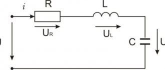
The current amplitude increases sharply with voltage resonance in the series circuit (series resonance). The source of alternating EMF is connected to a circuit where the series-connected elements L and C serve as the load.
In this case, the circuit includes resistances: active r and reactive x, equal to:
x = xL – xC.
Since for internal oscillations xL and xC are equal, then for the current supplied from the generator, at resonance (when the frequencies coincide) these values are also the same. Therefore x = 0. As a result, the total resistance of the circuit will consist of only a small active resistance. This results in maximum current.
Scheme (a) and resonance curves (b) for voltage resonance
Voltage amplitude
Current resonance (parallel resonance) is a condition for a sharp increase in voltage amplitude. The EMF source is connected outside the circuit and loaded by elements L and C connected in parallel. In this case, the resonance effect is affected by the internal resistance of the generator. The voltage amplitude on the circuit is maximum when the difference between the circuit voltage and the generator voltage is small. This is possible with small Ri.
Attention! Changing the generator frequency changes the current, and the voltage amplitude on the circuit does not lag behind the voltage on the generator. If U = E – I*Ri, where E is the emf, I is the current, then at small Ri U = E.
Scheme (a) and resonance curves (b) for current resonance
The formula for determining the calculated resonant frequency for different oscillatory systems differs in the parameters included in it. Despite all the differences, the essence remains the same: the resonance effect occurs when the frequency of internal oscillations of the system and external influences become equal to each other.
Making an inductor
All data is available, you can start manufacturing the inductor. To illustrate the connection of the coils, I will place here part of the circuit from my radio receiver.
Rice. 3. Diagram for connecting inductors in a radio receiver (the beginnings of winding are indicated by a dot).
If you look at the diagram, for one range you can wind only two coils on the frame: the contour coil will replace L1 and L2, and the communication coil will replace L3 and L4, while switch S1 can be eliminated.
I nevertheless decided to make 4 coils as in the diagram for the sake of experiment, I wonder how such a solution will behave in the HF range, besides, it is possible that it will be possible to capture an even lower frequency range in addition to the main one.
ATTENTION: it is necessary to observe the beginnings and ends of the winding when installing the coil, as well as the winding direction of each of the windings. Read in detail in the article: Homemade battery radio receiver using a 2K2M lamp.
The first step is to make a frame on which we will wind the wire. Under the frame, you can use a piece of polyethylene or plastic pipe or another cylinder of the required diameter.
I will need a frame with a diameter of 45mm, since I found a pipe with a slightly smaller diameter of 40mm in junk and in order not to spoil it, I decided to glue a paper frame around it.
Rice. 4. The frame for the coil is a piece of pipe.
For gluing I used A4 sheets - the paper is quite thick and well suited for such purposes. First, we wrap 1-2 sheets of paper onto the frame without covering it with glue, this is necessary so that we can then remove the pipe.
Rice. 5. Several layers of paper glued together for the frame of the future reel.
Now we spread glue on each sheet of paper and wrap the frame in it. It is advisable to stick 5 or more sheets of paper - this will help to achieve sufficient strength of the frame when it dries. Drying is enough for 12 hours if glued with PVA glue.
After the frame had dried, it turned out that it was so tight on the pipe that it was no longer possible to remove it - I had to cut the frame lengthwise and, after removing it, glue the cut. The frame is ready and it is strong enough to hang a thick wire on it.
Rice. 6. The paper frame for the inductor is ready.
For winding I used a copper conductor with a diameter of 0.8mm and 0.5mm - a loop and a communication coil, respectively.
Rice. 7. A homemade inductor for the HF range is ready!
Rice. 8. Homemade HF coil - view from the terminals.
For convenience, I marked the starting points for winding the coils - this will help you avoid getting confused when connecting it to the radio. The conductors were fastened by making holes in the frame using a needle.
Rice. 9. We fasten the turns of the windings with wax.
In order for the turns of the coil windings to stay securely together, you can glue them together with glue or simply drop a few drops of wax.