Ohm's law is an empirical physical law that determines the relationship between the electromotive force of a source (or electrical voltage) and the strength of the current flowing in a conductor and the resistance of the conductor. Established by Georg Ohm in 1826 (published in 1827) and named after him.
This review contains programs and calculators for Ohm's law. Also additionally given are the basic formulas and calculation methods.
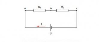
Ohm's law for direct current - calculation, formulas
Ohm's law for direct current determines the relationship between current (I), voltage (U) and resistance (R) in a section of an electrical circuit.
Ohm's law for a complete circuit:
I = ε / (R + r), where:
- ε —EMF of the voltage source, V;
- I is the current strength in the circuit, A;
- R is the resistance of all external elements of the circuit, Ohm;
- r is the internal resistance of the voltage source, Ohm.
The following consequences follow from Ohm's law for a complete circuit:
- When r < R, the current strength in the circuit is inversely proportional to its resistance, and the source itself in some cases can be called a voltage source.
- When r > R, the current strength does not depend on the properties of the external circuit (load magnitude), and the source can be called a current source.
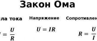
Often the expression I = U / R is also called Ohm's law. In this case, the formulation is as follows - the current strength in a section of the circuit is directly proportional to the voltage and inversely proportional to the electrical resistance of a given section of the circuit, where:
- I is the current strength, measured in Amperes (A).
- U is voltage measured in Volts (V).
- R is resistance measured in Ohms (Ohm, Ω).
In addition to Ohm's law, the most important concept is electrical power. DC power (P) is equal to current (I) times voltage (U):
P = I × U, where:
- P is electrical power, measured in Watts (W).
- I is the current strength, measured in Amperes (A).
- U is voltage measured in Volts (V).
By combining two formulas, we can obtain the relationship between current, voltage, resistance and power, and create a table:
Multiplying prefixes in the SI system are conciliatory to Ohm's law:
- Current strength, Amperes (A): 1 kiloampere (1 kA) = 1000 A; 1 milliamp (1 mA) = 0.001 A; 1 microamp (1 µA) = 0.000001 A.
- Voltage, Volts (V): 1 kilovolt (1kV) = 1000 V; 1 millivolt (1 mV) = 0.001 V; 1 microvolt (1 µV) = 0.000001 V.
- Resistance, Ohms (Ohm): 1 megaohm (1 MOhm) = 1,000,000 Ohm; 1 kiloohm (1 kOhm) = 1000 Ohm.
- Power, Watts (W): 1 megawatt (1 MW) = 1,000,000 W; 1 kilowatt (1 kW) = 1000 W; 1 milliwatt (1 mW) = 0.001 W.
Resistance change:
In the following diagram you can see the difference in resistance between the systems shown on the right and left side of the figure. The resistance to water pressure in the tap is counteracted by the valve; depending on the degree of opening of the valve, the resistance changes.
Resistance in a conductor is depicted as a narrowing of the conductor; the narrower the conductor, the more it opposes the passage of current.
You may notice that on the right and left sides of the diagram the voltage and water pressure are the same.
You need to pay attention to the most important fact. Depending on the resistance, the current increases and decreases
Depending on the resistance, the current increases and decreases.
On the left, with the valve fully open, we see the largest flow of water. And at the lowest resistance, we see the largest flow of electrons (Amperage) in the conductor.
On the right, the valve is closed much more and the flow of water has also become much greater.
The tension of the conductor also decreased by half, which means the resistance to the flow of current doubled. As we can see, due to the high resistance, half as many electrons flow through the conductor.
For reference
Please note that the constriction of the conductor shown in the diagram is used only as an example of resistance to current flow. In real conditions, the narrowing of the conductor does not greatly affect the flow of current
Semiconductors and dielectrics can provide significantly greater resistance.
The tapering conductor in the diagram is shown only as an example, to understand the essence of the process taking place. The formula of Ohm’s law is the relationship between resistance and current
I = E/R As you can see from the formula, the current is inversely proportional to the resistance of the circuit.
More resistance = Less current
* provided that the voltage is constant.
Ohm's law for an alternating current circuit
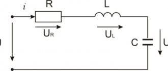
In an alternating current circuit, in addition to active resistance, resistance can have both capacitive and inductive components. Consider an alternating current circuit consisting of a resistor of resistance R, a capacitor of capacitance C, and a coil of inductance L, connected in series.
The instantaneous current values on all elements of this circuit are the same, and the instantaneous voltage value between the ends of the circuit is equal to the algebraic sum of the instantaneous voltage values on the resistor (UR), capacitor (UC) and inductor (UL).
In order to determine the amplitude (or effective) values of voltage and current, as well as the phase shift between them, it is convenient to use the vector diagram method. Here, the effective values of all voltages and currents are considered as vectors rotating with an angular velocity ω equal to the cyclic frequency of the alternating current, and their instantaneous values are determined by the projections of these vectors onto the horizontal axis. Since the current strength in the circuit is the same, the construction of the vector diagram begins with the vector I¯0, the magnitude of which is equal to the amplitude value of the current strength in the circuit. The direction of this vector can be any. Let us set the angle α = ωt to the horizontal.
The voltage oscillations across the active resistance are in phase with the current oscillations, so the vector U¯0R, the magnitude of which is equal to U0R = I0 × R, coincides in direction with the vector I¯0. The phase shift between the current fluctuations and the voltage fluctuations across the inductive reactance is π/2, with the current being out of phase with the voltage. Therefore, the vector U¯0L, whose modulus is equal to U0L = I0 × ωL, must be rotated relative to the vector I¯0 by an angle π / 2 counterclockwise. The vector U¯0C, whose modulus is equal to I0 / ωC, lags in phase from the vector I¯0 by π / 2, so it must be rotated clockwise by this angle.
In order to find the voltage at the circuit terminals, it is necessary to add three vectors: U¯0 = U¯0R + U¯0L + U¯0C.
First of all, let's add the vectors U¯0R and U¯0C. The modulus of this sum is U'0 = [U¯0R + U¯0C]. Let ωL > 1 / ωC, then: U'0 = I0 × (ωL - 1 / ωC).
Now let's add the vectors U¯0R and U'¯0. The modulus of the vector U¯0 is determined by the Pythagorean theorem: U0² = U0R² + (U0L - U0C)² = I0² × R² + I0² × (ωL - 1 / ωC)². Accordingly, the amplitude (effective) value of the current in an alternating current circuit is equal to the ratio of the amplitude (effective) value of the voltage at the ends of this circuit to its total resistance ( Ohm's law for an alternating current circuit ):
I0 = U0 / √(R² + (ωL - 1 / ωC)²) = U0 / Z, where:
- Z is the total resistance (impedance) of the circuit.
- R is its active resistance.
- ωL - 1 / ωC is the reactance of the alternating current circuit.
- ω = 2 × π × γ - cyclic, angular frequency. γ is the frequency of alternating current.
Impedance for parallel connection Z = 1 / √(1 / R² + 1 / (1 / ωL - ωC)²).
The phase shift between current and voltage is equal to the angle φ between vectors U¯0 and I¯0. According to the graph above, the current lags behind the voltage by an angle φ, with tanφ = (ωL - 1 / ωC) / R.
In order to determine the instantaneous voltage values on the active, capacitive and inductive reactances, it is necessary to project the vectors U¯0R, U¯0L, U¯0C onto straight line AB.
Then:
- UR = I0 × R × sin × (ωt + φ).
- UL = I0 × ωL × sin × (ωt + φ + π / 2).
- UC = (I0 / ωС) × sin × (ωt + φ - π / 2).
If 1 / ωС > ωL, then:
- U'0 = I0 × (1 / ωС - ωL).
- tgφ = (1 / ωC - ωL) / R, and the current is ahead of the voltage in phase by an angle φ.
What is the voltage drop across a resistor
Electric current passing through a circuit experiences resistance, which can change under the influence of various environmental conditions (extremely low temperatures or heat) and may depend on the characteristics of the particular conductor. For example, the thinner the conductor or longer, the higher it is.
The value of its value is influenced by the following factors:
- current strength;
- length of conductive parts;
- voltage;
- conductor element material;
- heating (temperature);
- cross-sectional area.
Resistors can be divided into constant, variable and trimming. Their main difference from each other is the ability to change the resistance indicator. The most common ones are fixed resistors - this indicator cannot be changed in them, which is why they got that name. Variables differ in that the resistance value in them can be adjusted. In a trimmer resistor it can also be changed, but the difference between this type is that it is not designed for frequent changes of the parameter. Trimmer resistors are made in a more compact package compared to variables.
To calculate the voltage drop across a resistor, you need to remember that the reduction in load applied to the entire circuit (that is, the voltage connected to the circuit) can be obtained both for the entire circuit and for any element in the circuit. The voltage is reduced due to the resistance that the conductors have.
The voltage drop across the resistor depends on the strength of the current passing and the characteristics of the conductors. Temperature and current readings also matter. For example, the voltage measured by a voltmeter on a light bulb connected to a 220 V network will be slightly lower due to the resistance that the light bulb has.
Power supplies have different voltage levels. This value may exceed what is needed at the output. To prevent the load that needs to be powered from burning out, it is often necessary to lower the voltage, including using resistors.
Voltage comparison table
| Power supply | Voltage |
| NiCd battery | 1.2 V |
| Lithium iron phosphate battery | 3.3 V |
| Battery type "Krona" | 9 V |
| Car battery | 12 V |
| Truck battery | 24 V |
In this case, the resistor should reduce the current flowing through the circuit. In this case, the current does not turn into heat, it is precisely its limitation that occurs. That is, when a resistor is connected to the circuit, the current will drop - this is the work of the resistor, during which the element heats up.
In general, voltage drops can be calculated using a simple formula that relates the indicators to each other.
But in some cases, for example, when connecting resistances in parallel, it is more difficult to calculate the required value. In this case, using a special formula, you will need to bring the resistance of parallel branches to one number:
R = R1*R2 / (R1+R2)
If necessary, other resistances that add up to this value are also taken into account (for example, resistance of the wire and power supply).
Conductor resistivity table
Electrical resistance (ρ) of 1 meter of wire, cross section 1 mm², at a temperature of 20 C°:
| Conductor material | Specific resistance ρ, Ohm |
| Silver | 0.015 |
| Copper | 0.0175 |
| Gold | 0.023 |
| Brass | 0,025. 0,108 |
| Chromium | 0,027 |
| Aluminum | 0.028 |
| Sodium | 0.047 |
| Iridium | 0.0474 |
| Tungsten | 0.05 |
| Zinc | 0.054 |
| Molybdenum | 0.059 |
| Nickel | 0.087 |
| Bronze | 0,095. 0,1 |
| Iron | 0.1 |
| Steel | 0,103. 0,137 |
| Tin | 0.12 |
| Lead | 0.22 |
| Nickelin (an alloy of copper, nickel and zinc) | 0.42 |
| Manganin (alloy of copper, nickel and manganese) | 0,43. 0,51 |
| Constantan (alloy of copper, nickel and aluminum) | 0,44-0,52 |
| Copel (copper-nickel alloy with 43% nickel and 0.5% manganese) | 0.5 |
| Titanium | 0.6 |
| Mercury | 0.94 |
| Chromel (chrome 8.7 - 10%; nickel 89 - 91%; silicon, copper, manganese, cobalt - impurities) | 1.01 |
| Nichrome (an alloy of nickel, chromium, iron and manganese) | 1,05. 1,4 |
| Fechral | 1,15. 1,35 |
| Bismuth | 1.2 |
| Chromal (Alloy 4.5 - 6% aluminum, 17 - 30% chromium, iron) | 1,3. 1,5 |
The conductor resistance is determined by the formula r = (ρ × l) / S, where:
- r — conductor resistance, Ohm.
- ρ —conductor resistivity, Ohm.
- l is the length of the conductor, m.
- S —conductor cross-section, mm².
Formula for calculating wire cross-section and how the wire cross-section is determined
Quite a lot of questions are associated with determining the cross-section of the wire when constructing electrical wiring. If we delve deeper into electrical engineering theory, the formula for calculating the cross section looks like this:
Of course, in practice, this formula is used quite rarely, resorting to a simpler calculation scheme. This scheme is quite simple: the current strength that will act in the circuit is determined, after which the cross-section is determined according to a special table. You can read more about this in the material – “Wire cross-section for electrical wiring”
Let's give an example. I have a 2000 W boiler, what size wire should it be to connect it to household electrical wiring? First, let's determine the current strength that will act in the circuit:
As you can see, the current strength is quite decent. We round the value to 10 A and refer to the table:
Thus, our boiler will require a wire with a cross-section of 1.7 mm. For greater reliability, we use a wire with a cross-section of 2 or 2.5 mm.
Expert opinion
Viktor Pavlovich Strebizh, lighting and electrical expert
Any questions ask me, I will help!
In a classic device, a measured current passes through an electromagnetic coil, which creates a magnetic field that causes the magnetic needle to deflect. If there is something you don’t understand, write to me!