Category:Electrical installation work
The source of electricity supply for most industrial enterprises is usually energy systems; In rare cases, enterprises receive energy from their own factory power plants. Electricity supply and energy distribution within the enterprise from its own power plants is carried out mainly at generator voltages of 6 and 10 kV.
Most enterprises receive power from district substations that are part of the energy system via high-voltage power lines through step-down transformers installed at consumer substations. Electricity supply to enterprises is carried out through electricity reception and distribution points (GPP, TsRP, RP and TP), as close as possible to consumers. An electrical installation that serves to receive and distribute electricity and contains switching devices, busbars and connecting buses, auxiliary devices (compressor, battery, etc.), as well as protection devices, automation and measuring instruments, is called a switchgear (RU).
Switchgears are divided into open switchgear (all or the main equipment is located in the open air) and closed switchgear (equipment is located in the building), as well as complete switchgear. A complete switchgear is a switchgear consisting of fully or partially closed cabinets or blocks with built-in devices, protection and automation devices, supplied assembled or fully prepared for assembly.
An electrical installation used for the conversion and distribution of electricity and consisting of transformers or other energy converters, switchgear, control devices and auxiliary structures is called a substation. Depending on the predominance of a particular function, substations are divided into transformer and converter ones.
A substation that receives power directly from the power system (or plant power plant) is called the main step-down substation (MSS) of the plant. Distribution of low-voltage energy from the GPP is carried out throughout the entire enterprise or a significant part of it through workshop transformer substations (TS), distribution points (DP) and central distribution points (CDP).
Transformer and converter substations, as well as distribution devices, are manufactured and supplied complete (KTP, KPP), assembled or fully prepared for assembly.
Electrical energy is generated, transmitted and consumed at various voltage levels. For general purpose electrical networks of alternating voltage with a frequency of 50 Hz and the electrical energy receivers connected to them, the following rated voltages are established: up to 1000 V - 40, 220, 380 and 660 V; above 1000 V-(3), 6, 10, 20, 35, 110, (150), 220, 330, 500, 750 and 1150 kV (voltages indicated in brackets are not recommended for newly designed networks).
Electrical installation work - Reception and distribution of electrical energy
Diesel power station
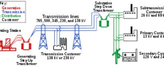
The electronic energy generated by the stations is supplied to the point of use through a system of interconnected transmission, distribution and modifying electrical installations. Electricity is transmitted via overhead power lines with voltages ranging from several hundred to hundreds of thousands of volts. Electronic energy is transmitted through system overhead networks with voltages of 35, 110, 150, 220 kV and higher on the rated voltage scale.
Installations used to receive and distribute electricity are called distribution devices (RU). They contain switching devices, busbars and connecting busbars, auxiliary devices (compressor, battery and others), as well as protection devices, automation and measuring instruments. Distribution centers include power centers (CP), distribution points (DP), distribution strips (RL).
Construction of the Power Plant
A power center is a generator voltage switchgear of a power plant or a secondary voltage switchgear of a step-down substation of a power system with a regulation system, to which the distribution networks of a certain area are connected.
A distribution substation is a substation of an industrial enterprise or a city electronic network, created to receive and distribute electricity with one voltage without converting it.
A distribution line is a line that supplies a number of transformer substations from the CPU or RP, as well as large electrical installations.
Switchgears can be open (OSG—all or the main equipment is located in the open air) and closed (OSU—equipment is located in the building). It is especially necessary to highlight the more widespread complete switchgears (KRU), consisting of completely or partially closed cabinets or blocks with devices, protection and automation devices built into them, supplied assembled or completely prepared for assembly and produced for both internal and external use. external installation.
Block complete transformer substation
A substation is an electrical installation used to convert and distribute electricity and consisting of transformers or other energy converters, switchgear, control devices and auxiliary structures.
The substation at which the alternating current voltage is converted using a transformer is called a transformer station (TP). If the alternating current voltage at a transformer transformer is converted to a lower voltage, it is called a step-down voltage, and if it is converted to a higher voltage, it is called a step-up voltage.
At transformer substations, transformers are installed that serve to configure the voltage. Immediately with the voltage transformation, the number of lines usually changes. For example, one or two high-voltage lines approach a transformer substation, and several low-voltage lines depart from it.
There are two types of transformer substations: open, in which the main equipment is located in open areas, and closed, in which the equipment is located in premises.
If voltage transformation is not done at a substation, but only the number of lines changes, then it is called distribution.
Converter substations are used to rectify alternating current or convert direct current into alternating current. At all substations, devices for switching electronic networks and various control and measuring instruments are installed.
Complete transformer substation for external installation
Electronic networks are divided according to low voltage - up to 1 kV and high voltage - more than 1 kV.
Most industrial companies receive electricity from substations. At substations, two or more transformers are installed, through which energy from the power system is transmitted through high-voltage lines (35, 110 or 220 kV) to sectionalized operating (or spare) busbars with a voltage of 6...10 kV.
A substation that is powered specifically from the energy system (or a factory power plant) is called the main step-down substation (MSS) of the enterprise, and a substation at which the voltage is reduced specifically to power the electrical receivers of 1 or several workshops is called a workshop transformer substation (TS).
Transformer and converter substations, as well as distribution devices, are supplied complete (KTP, KPP) assembled or fully prepared for assembly.
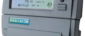
Measurement of current and voltage on the buses of distribution devices and in electronic circuits is done using current transformers or voltage transformers, which serve to reduce the current or voltage of the primary circuits of alternating current electrical installations, as well as to power the coils of measuring devices, relay protection and automation devices connected to their secondary windings
The use of instrument transformers allows:
determine any voltages and currents using ordinary measuring devices with standard windings designed for a voltage of 100 V and a current of 5 A;
separate measuring instruments and relays from voltages above 380 V, ensuring the safety of their maintenance.
The primary winding of the measuring transformer is under the influence of the measured value, and the secondary winding is closed to measuring instruments and protection devices.
Open switchgear
Touching measuring devices specifically included in the high-voltage circuit is unsafe for humans, therefore, in this case, measuring instruments and automatic protection equipment (relays) are connected to the secondary circuit of instrument transformers, connected to the high-voltage circuit only through the magnetic flux in the core. In addition, instrument transformers serve to expand the measurement limits of AC devices, like additional resistors and shunts. The use of instrument transformers with different transformation ratios allows the use of devices with standard measurement limits (100 V and 5 A) when determining a wide variety of voltages and currents.
There are two types of instrument transformers: voltage transformers and current transformers.
Voltage transformers supply voltage windings of measuring devices and relays (voltmeters, frequency meters, meters, wattmeters, voltage relays, power relays, etc.) in installations with voltages of 380 V and higher.
Current transformers supply current windings of measuring devices and relays (ammeters, meters, wattmeters, current, power relays, etc.).
The sources of power supply for most industrial companies are power systems, but some enterprises receive energy from their own industrial power plants. The generation and distribution of energy within the boundaries of the enterprise from its own power stations is carried out mainly in generator mode with a voltage of 6 and 10 kV.
Constant current switchgears of the KV series for voltage 3.3 kV
Electronic circuits of switchgears and substations can be primary and secondary.
Primary circuits include busbar devices and current-carrying parts of devices connected in a certain sequence.
Secondary circuits include circuits with the help of which electronic measurements, relay protection, alarms, remote control and automation are carried out in the primary circuits of switchgear substations, i.e. Secondary circuits provide control, protection, comfortable and non-hazardous service to primary circuits.
Schematic diagrams of primary circuits show all the main elements of an electrical installation: busbar devices, disconnectors, switches, fuses, transformers, reactors, etc., as well as connections between them. In addition to better understanding the operation of the installation and its individual sections, primary circuits usually show main devices and devices of secondary circuits, measuring instruments, relay protection and automation devices without electronic connections.
Modern switchgears may have different connection schemes.
In addition, you need to remember that disconnecting a load-free strip is associated with a break in its charging current, which is greater the longer the line is.
A load switch installed instead of a disconnector allows you to turn off and turn on the line when the load is within the rated limits.
In this case, measuring current transformers are installed at the connection, and line and bus disconnectors are used to relieve voltage from the switch and current transformers during inspection, repair, testing and other work.
Because actions with disconnectors are only possible when the switch is turned off, which breaks the current circuit, the order of disconnecting the strip is as follows: first the switch is turned off, then the line disconnector and finally the bus disconnector. The order of turning on the strip is reversed. This option of connecting to the switchgear is used for lines with heavy loads and huge short-circuit current.
FGC UES completed the installation of 10 kV indoor switchgear equipment at the 110 kV Rosa Khutor substation in the Sochi region
Typically, this scheme is used to connect overhead lines.
In this case, the grounding legs serve to ground and short-circuit the strip after disconnection, because in the disconnected strip there may be the appearance of electronic charges induced by atmospheric electricity or nearby lines. The arresters are designed to discharge electronic charges of atmospheric electricity into the ground, creating significant overvoltages in the switched-on strip that are unsafe for the entire installation. In open switchgears, arresters are connected directly to the main buses.
. To disconnect this transformer from the network, use a bus disconnector (disconnection should only be performed when the transformer is idle); Protection against high and low voltages is provided by fuses.
This circuit includes a switch designed for operational switching and relay protection (RP), the devices of which are powered by measuring current transformers.
The use of complete switchgears and transformer substations makes it possible to reduce installation time, reduce their price and improve quality.
How is electricity distributed and transferred from the main power source to the consumer? This issue is quite complex, since the source is a substation, which may be located at a considerable distance from the city, but at the same time the energy must be delivered with maximum efficiency. This issue is worth considering in more detail.
General description of the process
As mentioned earlier, the initial object from which the distribution of electricity begins is today a power station.
Nowadays, there are three main types of stations that can supply consumers with electricity. This can be a thermal power plant (TPP), a hydroelectric power station (HPP) and a nuclear power station (NPP). In addition to these main types, there are also solar or wind power plants, however these are used for more localized purposes.
These three types of station are both the source and the first point of distribution of electricity.
In order to carry out a process such as the transfer of electrical energy, it is necessary to significantly increase the voltage. The further away the consumer is, the higher the voltage should be. So, the increase can reach up to 1150 kV.
An increase in voltage is necessary in order for the current to decrease. In this case, the resistance in the wires also drops. This effect allows current to be transmitted with minimal power loss.
In order to increase the voltage to the required value, each station has a step-up transformer. After passing through the section with the transformer, the electric current is transmitted to the central distribution center using power lines. The central distribution station is a central distribution station where direct distribution of electricity is carried out.
Facilities such as central distribution centers are already located in close proximity to cities, villages, etc.
d. Not only distribution occurs here, but also voltage reduction to 220 or 110 kV. After this, the electricity is transferred to substations located within the city. When passing through such small substations, the voltage drops again, but to 6-10 kV.
After this, the transmission and distribution of electricity is carried out at transformer points located in different parts of the city. It is also worth noting here that the transmission of energy within the city to transformer substations is no longer carried out using power lines, but using laid underground cables. This is much more expedient than using power lines. The transformer point is the last facility where the distribution and transmission of electricity takes place, as well as its reduction for the last time. In such areas, the voltage is reduced to the already familiar 0.4 kV, that is, 380 V.
Then it is transmitted to private, multi-storey buildings, garage cooperatives, etc. If we briefly consider the transmission path, it is approximately as follows: energy source (10 kV power plant) - step-up transformer up to 110-1150 kV - power transmission line - substation with transformer step-down type - transformer point with voltage reduction to 10-0.4 kV - consumers (private sector, residential buildings, etc.).
Tires, wires, cables
4.1.15. Exposed live parts must generally have an insulating coating. Between fixedly fixed live parts of different polarity, as well as between them and open conductive parts, distances of at least 20 mm along the insulation surface and at least 12 mm in the air must be provided. From non-insulated live parts to fences, distances of at least 100 mm for mesh fences and 40 mm for solid removable fences must be provided.
4.1.16. Within panels, switchboards and cabinets installed in dry rooms, insulated wires with insulation rated for a voltage of at least 660 V can be laid on metal surfaces protected from corrosion close to each other. In these cases, the reduction factors for current loads given in Chapter. 2.1.
4.1.17. Protective (PE) conductors and busbars can be laid without insulation. Zero working (N) conductors, busbars and combined (PEN) conductors are laid with insulation.
4.1.18. Electrical wiring of control circuits, measurements and others must comply with the requirements of Chapter. 3.4. Cable routing must comply with chap. 2.3. Cable passages both from below and from above, inside panels, cabinets, etc. must be carried out through sealing devices that prevent dust, moisture, foreign objects, etc. from entering.
Process Features
The production and distribution of electricity, as well as the process of its transmission, has an important feature - all these processes are continuous. In other words, the production of electrical energy coincides in time with the process of its consumption, which is why power stations, networks and receivers are interconnected by such a concept as common mode. This property necessitates the organization of energy systems in order to more efficiently produce and distribute electricity.
It is very important here to understand what such an energy system is. This is a collection of all stations, power lines, substations and other heating networks that are interconnected by such a property as common mode, as well as a single process of producing electrical energy. In addition, the transformation and distribution processes in these areas are carried out under the overall control of this entire system.
The main operating unit in such systems is the electrical installation. This equipment is designed for the production, conversion, transmission and distribution of electricity.
This energy is obtained by electrical receivers. As for the installations themselves, depending on the operating voltage, they are divided into two classes. The first category works with voltages up to 1000 V, and the second, on the contrary, with voltages from 1000 V and above.
In addition, there are also special devices for receiving, transmitting and distributing electricity - switchgear (RU). This is an electrical installation that consists of such structural elements as busbars and connecting busbars, switching and protection devices, automation, telemechanics, measuring instruments and auxiliary devices.
These units are also divided into two categories. The first is open devices, which can be used outdoors, and closed ones, used only when located inside a building. As for the operation of such devices within the city, in most cases it is the second option that is used.
One of the last frontiers of the power transmission and distribution system is the substation. This is an object that consists of switchgear up to 1000 V and from 1000 V, as well as power transformers and other auxiliary units.
Additional classifications
There are two groups. The first is represented by open switchgear devices (OSD). The second is closed switchgear devices (SGD).
Elements for assembling outdoor switchgear are installed in open areas, without protection from damage caused by nature and climate. The operating voltage is 27.5 kV. Concrete is considered the most reliable foundation for outdoor switchgear. The distance between elements is selected according to the PUE.
Advantages of outdoor switchgear: the main advantage over closed switchgear is the simple installation and installation of equipment. The outdoor switchgear allows the use of many electronic devices. Due to this, they are used in large enterprises for high voltages.
Disadvantages of outdoor switchgear: the main disadvantage is the difficulty of installing and operating outdoor switchgear equipment in unfavorable natural conditions. Too hot or cold climates lead to rapid wear of products. In addition, outdoor switchgear takes up three times more space than indoor switchgear.
Closed switchgear conductors are always located indoors. This provides protection from the negative effects of climate and bad weather. It is possible to equip equipment in sealed installations in fresh air using conventional meters. Operating voltage: 35 kV.
When using closed switchgear in cold climatic conditions, a special improved model of equipment with a special voltage (not higher than 800 kV) is offered.
Advantages of ZRU. Full factory readiness. Operation in difficult climate conditions is possible. It is possible to place indoor switchgear in the walls (for aesthetics) during construction. Long shelf life and low percentage of wear. Overall transportation dimensions.
Disadvantages of ZRU. Expensive installation and installation of equipment. Difficulty in localizing accidents (fires, explosions) during major accidents in indoor switchgear equipment. High price.
RU are:
- Traditional: all controls, instruments and displays are located on the front panel. Everything else is on the inside of the board.
- Functional: sorting equipment with additional switchgear and units for connection, installation and interconnection functions.
According to functionality, RU is also divided into:
- Main: responsible for the main voltage transmission;
- Decreasing or increasing: responsible for delivering a certain voltage to the device.
- For personal needs: responsible for transmitting electricity to stations or substations
Consideration of power distribution scheme
In order to consider in more detail the process of production, transmission and distribution of electricity, we can take as an example the structural diagram of the supply of electrical energy to a city.
In this case, the process begins with the generators at the state district power station (state district power plant) generating a voltage of 6, 10 or 20 kV. In the presence of such voltage, transmitting it over a distance of more than 4-6 km is not economical, since there will be large losses. In order to significantly reduce power loss, a power transformer is included in the transmission line, which is designed to increase the voltage to values such as 35, 110, 150, 220, 330, 500, 750 kV.
The value is selected depending on how far away the consumer is. This is followed by a point for reducing electrical energy, which is presented in the form of a step-down substation located within the city. The voltage is reduced to 6-10 kV.
It is worth adding here that such a substation consists of two parts. The first part of the open type is designed for voltage 110-220 kV. The second part is closed and includes a power distribution device (PD), designed for a voltage of 6-10 kV.
In addition to those devices that were listed earlier, the energy supply system also includes such objects as a supply cable line - PKL, a distribution cable line - RKL, a cable line with a voltage of 0.4 kV - KL, an input-type switchgear in a residential building – ASU, the main step-down substation at the plant – GPP, an electricity distribution cabinet or a switchboard device, located in the plant workshop, and designed for 0.4 kV.
Also in the circuit there may be such a section as the power center - the CPU. It is important to note here that this object can be represented in terms of two different devices.
This could be a secondary voltage switchgear at a step-down substation. In addition, it will also include a device that will perform the functions of voltage regulation and subsequent delivery to consumers. The second design option is a transformer for the transmission and distribution of electricity, or a generator voltage distribution device directly at the power station.
It is worth noting that the CPU is always connected to the distribution point of the distribution center. The line that connects these two objects has no distribution of electrical energy along its entire length. Such lines are usually called cable lines.
Today, the energy network can use equipment such as KTP - a complete transformer substation. It consists of several transformers, a distribution or input device, designed to operate with a voltage of 6-10 kV. The kit also includes a 0.4 kV switchgear.
All these devices are connected to each other by conductors, and the kit is supplied either ready-made or ready for assembly. Reception and distribution of electricity can also occur on high structures or on power transmission towers. Such structures are called either pole-mounted or mast-mounted transformer substations (MTS).
Requirements
Input and distribution devices can be designed as electrical equipment of class I or class II.
“Class I ASU structural elements related to frames, shells and other conductive parts should be made primarily of steel with a protective coating. »
clause 6.2.1 [3]
“ Class II ASU shells, if they do not serve as supporting elements for live parts, must be made of insulating materials that are resistant to ignition when exposed to wire heated to a temperature of (850 ± 10) ° C, when the ASU is built into low-flammable walls - up to ( 650±10)°С (according to GOST IEC 60439-3). »
clause 6.2.2 [3]
Kharechko Yu.V. the requirements of paragraphs 6.6 and 6.2.19 of GOST 32396-2013 were formulated as follows [2]:
“The design of the input distribution device must provide one-way service from the front side. Controls for switching equipment and control equipment are located behind the doors of the ASU. Input and distribution devices that are installed in electrical rooms are usually made with a degree of protection of at least IP2X on the front and sides and IP00 on the top, bottom and rear. ASUs installed outside electrical rooms must have a degree of protection (with doors closed) of at least IP31 on all sides, except for the lower base adjacent to the floor. The degree of protection provided by the operational panel when the ASU doors are open must be at least IP2X. In a cabinet-type input distribution device of class I, the operating panel can be made of conductive or insulating material, and in a class II ASU - only of insulating material. »
[2]
Kharechko Yu.V. in his dictionary [2] formulated the requirements of clauses 6.2.8, 6.2.9 and 6.2.14 from [3] as follows:
“ASU input and distribution blocks must have sufficient volume to accommodate conductors and connect conductors to switching and control equipment, to busbars and terminal blocks, which is carried out in compliance with the standardized bending radii of insulated wires and cable cores. These blocks must have elements for fastening wires and cables. Surge protection devices are also installed in the ASU input blocks, which are connected after the input protective equipment. »
[2]
Based on clauses 6.2.15, 6.2.17 from [3] Kharechko Yu.V. formulated the following requirements [2]:
“In single-panel ASUs and input panels of multi-panel ASUs, special compartments with doors should be provided to accommodate electricity metering units. The doors must be locked with a key and have elements for sealing them. In a cabinet-type ASU, the input terminals for the conductors of the power supply network and the metering circuit should be located behind the operating panel, which should be equipped with elements for sealing, while the metering units may not be separated into separate compartments. »
[2]
According to clause 6.2.29 of GOST 32396-2013:
“To take meter readings, the doors of the compartments or the doors of single- and multi-panel ASUs must have windows covered with impact-resistant transparent material. Such windows can also be provided in the doors of cabinet-type ASUs. It is allowed not to install windows for taking meter readings in ASUs installed in electrical rooms. »
[3]
The cross-sections of the phase busbars of the ASU are selected depending on the values of the rated currents of the input equipment given in Table 2 of GOST 32396-2013, taking into account their permissible heating.
The cross-sections of the protective bus PE and the neutral bus N are taken depending on the cross-section of the phase buses in accordance with the requirements of tables 3 and 4 of GOST 32396-2013 [3]. Table 3 - Sections of phase and corresponding protective conductors PE, mm2 (based on GOST 32396-2013)
| Phase conductor cross-section S, mm2 | Cross-section of the corresponding protective conductor, mm2 | |
| S ≤ 16 | S | |
| 16 < S ≤ 35 | 16 | |
| 35 < S ≤ 400 | S/2 | |
| 400 < S ≤ 800 | 200 | |
| Note – If the material of the protective conductor differs from the phase conductor, then its cross-section must be such that it provides conductivity equivalent to the conductivity of the corresponding cross-section of the conductor given in the table. | ||
Table 4 - Cross-sections of phase and corresponding neutral conductors N, mm2 (based on GOST 32396-2013)
| Phase conductor cross-section S, mm2 | Cross section of the corresponding neutral conductor, mm2 | |
| three-phase circuits | single-phase circuits | |
| S ≤ 16 | S | S |
| S>16 | S/2 | S |
“ASU busbars are equipped with special clamps, through which dismountable connections of phase, neutral and protective conductors are made. The number of clamps on the busbars and their cross-sections must correspond to the number of conductors of external and internal electrical circuits connected to them and their cross-sections. Busbars must withstand electrodynamic and thermal effects caused by short-circuit currents. »
[2]
“Input distribution devices must be provided with clamps designed for connecting conductors of external electrical circuits and having means for stabilizing contact pressure. As a rule, one conductor must be connected to each protective or neutral conductor terminal. In Class I ASUs, the terminals for neutral conductors must be insulated from their conductive shells in the same way as the terminals for phase conductors, and the terminals for protective conductors must have electrical connections to the shells. In Class II ASUs, the terminals for protective and neutral conductors must be insulated from their conductive shells in the same way as the terminals for phase conductors. »
[2]
“Exposed conductive parts of class I input distribution devices must be reliably connected to each other and connected to their protective busbars. The resistance between the protective bus and each open conductive part of the ASU should be no more than 0.1 Ohm. »
[2]
“The internal electrical circuits of the ASU should be made with insulated copper wires. Busbars, as a rule, should be copper. Aluminum busbars can be used, with the exception of PE protective busbars, which can be made of coated steel. In this case, the conductivity of the steel busbars must match the conductivity of the copper busbars. »
[2]
“Wires of internal electrical circuits, having small cross-sections, are usually laid in input distribution devices in bundles or placed in boxes. The number of wires combined into a bundle or laid in a box is determined by the conditions of their permissible heating when electric currents flow through them equal to the rated currents of the equipment to which they are connected. The insulation resistance of the internal circuits of the ASU in a cold state must be at least 10 MOhm. »
[2]
According to paragraph 6.8.1 from [3]:
“At rated currents of cabinet-type and single-panel ASUs, as well as at rated currents of multi-panel ASU panels, the temperature of their parts exceeds the ambient temperature and the permissible heating temperature of these parts at an ambient temperature of 35 °C should not exceed the values given in Table 5 of GOST 32396-2013. »
[3]
Table 5 - Temperature rise, °C (based on GOST 32396-2013)
| Part of the ASU | Permissible temperature rise above ambient temperature 35 °C1) | Permissible heating temperature, °C |
| Contact connections of equipment terminals, contact clamps with internal and external conductors | 55 | 90 |
| Bare conductors (busbars) | 55 | 90 |
| PVC insulated conductors | 35 | 702) |
| Insulating material controls | 20 | 55 |
| Accessible parts of the shell: – metal – made of insulating material | 20 55 | 55 60 |
| 1) At an upper ambient temperature value other than 35 °C, the permissible temperature rises can be changed within the limits of the specified permissible heating temperatures. 2) The permissible heating temperature of conductors with other types of insulation is established in the technical specifications for specific types of ASUs. | ||
According to clause 6.9.1 from [3]:
“Metal parts of the ASU must have protective paint, polymer powder and (or) metal coatings. »
[3]
GOST 32396-2013 (clause 6.10.2) established the service life of input distribution devices equal to 25 years. During this period, replacement of individual components of the ASU is allowed.
Requirements for color and alphanumeric marking of conductors in ASU.
Marking of conductors in input distribution devices should be carried out in accordance with the requirements of GOST 33542-2015 (IEC 60445:2010) [4], which established general rules for the use of certain colors and alphanumeric designations to identify conductors in order to ensure safety during the operation of electrical equipment and electrical installations . The colors and alphanumeric designations of conductors established in GOST 33542-2015 are intended for use in cable products, buses, electrical equipment and electrical installations.
Protective conductors PE should be green-yellow, and neutral conductors N should be blue.
The requirements of GOST 33542-2015 prohibit the use of yellow and green colors separately for marking conductors. Yellow and green are also prohibited from being used in any two-color combination other than the yellow-green color combination.
Protective and neutral buses must be designated PE and N, respectively. Wires of internal electrical circuits must have digital markings at the ends in accordance with the circuit diagrams of the ASU. At the ends of the prefabricated phase busbars, unless otherwise indicated on the circuit diagrams, the signs L1, L2, L3 should be applied.
Phase conductors in single-phase electrical circuits should be identified in brown, in three-phase electrical circuits - brown, black and gray. The alphanumeric identification of the phase conductor of a single-phase electrical circuit should be “L”, the phase conductors of a three-phase electrical circuit should be “L1”, “L2” and “L3”.
If a single-phase electrical circuit is a branch of a three-phase electrical circuit, the color and alphanumeric identification of the phase conductor of the single-phase electrical circuit must match the color and alphanumeric identification of the phase conductor of the three-phase electrical circuit with which it has an electrical connection.
First category of electrical receivers
Today there are three categories of electrical receivers, which differ in the degree of reliability.
The first category of electrical receivers includes those objects where, if the power supply is disrupted, quite serious problems arise. The latter include the following: a threat to human life, severe damage to the national economy, damage to expensive equipment from the main group, massive defective products, destruction of the established technological process for obtaining and distributing electricity, possible disruption of the operation of important elements of public utilities.
Such electrical receivers include buildings with large crowds of people, for example, a theater, supermarket, department store, etc. Electrified transport (metro, trolleybus, tram) also belongs to this group.
As for the supply of electricity to these structures, they must be provided with electricity from two sources that are independent of each other.
Disconnection of such buildings from the network is allowed only for the period during which the backup power source will be started. In other words, the power distribution system must provide for a quick transition from one source to another in the event of an emergency. In this case, an independent power source is considered to be one on which the voltage will remain even if it disappears on other sources powering the same electrical receiver.
The first category also includes devices that must be powered from three independent sources at once.
This is a special group whose operation must be ensured in uninterrupted mode. That is, disconnection from the power supply is not allowed even while the emergency source is turned on. Most often, this group includes receivers whose failure entails a threat to human life (explosion, fire, etc.).
Substation construction
The substation includes many different elements that allow the entire system to operate continuously and stably for a long time. All elements can be divided into several systems:
- automatic control;
- electricity metering;
- relay and emergency protection;
- lightning protection;
- grounding;
- auxiliary, which included systems for security functions, melting snow and ice on lines, local lighting, oil collection and power supply for oil-filled cables, as well as household consumption systems.
Despite this internal multi-structural systematization, substations consist of the following basic devices that ensure their normal functionality:
- converting power transformers of certain power characteristics;
- power distribution device, including structures for overhead and cable power transmission;
- protection devices;
- automatic control devices;
- auxiliary devices that ensure stable operation of substations under any weather and time conditions.
When choosing transformer substations, there is often a question about price and the difference between more expensive ones and more budget ones. First of all, they differ in the quantitative composition of transformers, the set of voltage input and distribution devices, as well as devices that allow such stations to be used in certain conditions.
Thus, more expensive substations can be equipped with devices for protection against lightning, against weather conditions: ice, wind, rain, protection against breaks and sudden voltage changes in the system, as well as other devices that allow the use of substations on moving platforms, for example, in mines , high-mountain mining enterprises, in humid climatic zones and other places of human activity.
Second and third categories of receivers
Electricity distribution systems with the connection of the second category of electrical receivers include such equipment, if the power is turned off, there will be a massive downtime of working mechanisms and industrial vehicles, a shortage of products, as well as disruption of the activities of a large number of people living both within the city and outside it. outside. This group of electrical consumers includes residential buildings above the 4th floor, schools and hospitals, power plants, the power outage of which will not result in the failure of expensive equipment, as well as other groups of electrical consumers with a total load of 400 to 10,000 kV.
Energy sources of this category should be two independent stations. In addition, disconnection from the main power source of these objects is allowed until the personnel on duty puts the backup source into operation, or the duty team of workers at the nearest power supply station does this.
As for the third category of receivers, these include all the remaining devices that can be powered by just 1 power source. In addition, such receivers may be disconnected from the network during repairs or replacement of damaged equipment for a period of no more than 24 hours.
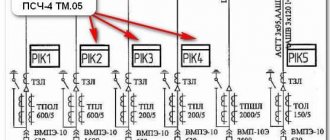
Maintenance of complete distribution devices
Before starting the inspection of the switchgear, there should be no extraneous noise or characteristic crackling or smoke inside the cabinets. If they do occur, in this case, remote voltage relief is carried out from the damaged equipment.
During the inspection of devices, without disconnecting them from the voltage, the condition of the following places is checked:
- Functioning of the lighting network, as well as the heating system for cabinets and rooms in the cold season.
- The oil level in the equipment where it is used, the absence of oil drips and leaks.
- The condition of contact connections, disconnecting devices, blocking mechanisms available for inspection and the main circuit - switchgear.
- Clamps, flexible connections, plug connectors, relays and other elements of secondary circuits.
- Condition and readings of instrumentation and other low-voltage equipment.
Visual observation is carried out using observation windows and mesh fences. If any violations that could cause an accident are detected, they must be eliminated immediately. Other defects that do not require urgent action are recorded in the log for further elimination.
High humidity often leads to wetting of the surface of the insulators and damage to the entire insulation. In order to eliminate such phenomena, regular cleaning of dust and lubrication of insulators with hydrophobic paste are carried out. The cabinets themselves provide a microclimate with a relative air humidity level of 60-70%. Electric heaters are installed inside the cabinets, and their walls are insulated with mineral wool slabs. Equipment malfunctions occur at subzero temperatures.
Schematic diagram of the supply and distribution of electrical energy
Control of the distribution of electricity and its transmission from source to receiver of the third category within the city is most easily accomplished using a radial dead-end circuit.
However, such a circuit has one significant drawback, which is that if any one element of the system fails, all receivers connected to such a circuit will be left without power. This will continue until the damaged section of the chain is replaced. Due to this drawback, it is not recommended to use such a connection scheme.
If we talk about the connection and energy distribution diagram for receivers of the second and third categories, then here you can use a ring circuit diagram.
With this connection, if there is a failure in the operation of one of the power lines, you can restore the power supply to all receivers connected to such a network manually by turning off the power from the main source and starting the backup one. The ring circuit differs from the radial circuit in that it has special sections in which disconnectors or switches are located in the off mode. If the main power source is damaged, they can be turned on to restore supply, but from the backup line.
This will also serve as a good advantage if any repair work needs to be carried out on the main line. A break in the power supply to such a line is allowed for a period of about two hours. This time is enough to turn off the damaged main power source and connect the backup one to the network so that it distributes electricity.
There is an even more reliable way to connect and distribute energy - this is a circuit with parallel connection of two supply lines or the introduction of automatic connection of a backup source.
With such a scheme, the damaged line will be disconnected from the general distribution system using two switches located at each end of the line. In this case, the supply of electricity will be carried out in a still uninterrupted mode, but through the second line. This scheme is relevant for receivers of the second category.
How to choose a scheme
The circuit is selected according to the number of connections and active DC voltage. There are facts that influence the scheme.
At the same time, attention is paid to:
- Power plant systems.
- Characteristics of generator sets.
- Connecting number of lines.
- Circuits and voltage levels.
- Indicators of short circuit currents.
- Operating capabilities of the switchgear according to the diagrams.
- Type - ZRU, ORU, KRU, KRUZ
It is important to consider the characteristics of the circuit. The dimensions and reliability of the power supply circuit are of great importance. First of all, they are determined for the purpose of installing the circuit. It is worth choosing the supplier and circuit status carefully.
Distribution schemes for the first category of receivers
As for the distribution of energy to power receivers of the first category, in this case it is necessary to connect from two independent power centers simultaneously. In addition, in such schemes, not one distribution point is often used, but two, and a system for automatically turning on backup power is always provided.
For electrical receivers that belong to the first category, automatic switching to backup power is installed on input distribution devices. With this connection system, the distribution of electric current is carried out using two power lines, each of which is characterized by a voltage of up to 1 kV, and is also connected to independent transformers.
Protection and safety measures
During operation of the switchgear, maintenance personnel must be reliably protected from electric shock. In addition, it is necessary to protect the equipment itself from short circuits and other emergency situations. The main reason is considered to be poor-quality installation and violations during further operation.
Most short circuits affect cable terminations. The damage begins to develop further because there are no partitions between the cable and switch compartments. Numerous holes in cells lead to arc spread to equipment and busbars of other cells. Similar situations arise in cases of failure and damage of switches.