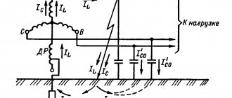
Networks with a voltage of 6-35 kV operate predominantly in the mode with an isolated neutral. In normal mode, load currents flow through the phase wires of such a network, as well as capacitive and leakage currents.
Network with isolated neutral in normal mode
Capacitive currents are caused by the phase capacitance relative to the ground, and leakage currents are caused by the active conductivity of the insulation. Compared to capacitive currents, leakage currents are small and amount to 2-6% of capacitive currents, so they can be neglected in calculations.
When one phase, for example phase “C”, is short-circuited to ground, the neutral voltage Un becomes equal to the voltage of the damaged phase. The current distribution pattern changes accordingly.
Since, as a result of damage, the capacitance of phase “C” becomes shunted, the voltage Ucn = 0 (if we neglect the voltage drop across the longitudinal resistance of the power line), the capacitive current due to the capacitance C0c becomes equal to zero.
In this case, a capacitive ground fault current will flow through the damaged phase “C”, equal to the capacitive current of the undamaged phases
Iз = -(IсА + IсВ).
The “-” sign indicates that the current is directed in the opposite direction, that is, towards the power source, and not away from it.
Network with isolated neutral during short circuit
To determine the settings for the operation of current protection against ground faults, the need to compensate for capacitive ground fault currents, it is necessary to be able to determine the ground fault current of the line.
1. Main characteristics of OZZ
One of the most common types of faults on power lines is a single-phase ground fault (SGF), a type of fault in which one of the phases of a three-phase system is shorted to ground or to an element electrically connected to ground. SPD is the most common type of damage, accounting for about 70-90% of all damage in electrical power systems. The course of physical processes caused by this damage largely depends on the operating mode of the neutral of a given network.
In networks where a grounded neutral is used, a phase-to-ground fault results in a short circuit. In this case, the short-circuit current flows through a closed circuit formed by grounding the neutral of the primary equipment. Such damage leads to a significant jump in current and, as a rule, is immediately turned off by the action of a relay protection, by disconnecting the damaged area.
Electrical networks of voltage classes 6-35 kV operate in a mode with an isolated neutral or with a neutral grounded through a large additional resistance. In this case, a phase-to-ground short circuit does not lead to the formation of a closed circuit and the occurrence of a short circuit, but the short circuit is closed through the capacitances of the undamaged phases.
The magnitude of this current is insignificant (reaches about 10-30 A) and is determined by the total capacity of the undamaged phases. In Fig. Figure 1 shows diagrams of a 3-phase network in modes before and after the occurrence of an electrical fault.
Figure 1 – Network diagram with an isolated neutral a) in normal mode;
b) with OZZ Such damage does not require immediate shutdown, however, its prolonged impact can lead to the development of an emergency situation. However, during OZZ in networks with an isolated neutral, processes occur that affect the operating mode of the electrical network as a whole.
In Fig. Figure 2 shows a vector diagram of voltages.
Figure 2 – Voltage vector diagrams a) in normal mode; b) with acute respiratory disease
In the case of OZZ, a violation of the symmetry of linear phase voltages occurs, the voltage of the damaged phase decreases to almost 0, and the two “healthy” phases rise to the linear level. In this case, the linear voltages remain unchanged.
General insulation monitoring in distribution networks 6 – 35 kV
To detect violations of phase insulation relative to ground in electrical installations, so-called general insulation monitoring is provided. For these purposes, a special three-phase five-rod voltage transformer is used, one of the secondary windings of which is connected into an “open delta” and is a zero-sequence voltage filter (ZVF) (Fig. 7). A KV voltage relay is connected to the output of this filter. When a phase is shorted to ground, a zero-sequence voltage of 3 U
, under the influence of which the relay is activated and acts on the signal. The damaged phase is determined, as a rule, by three voltmeters connected to another secondary winding of the voltage transformer. In this case, the voltmeter readings in the damaged phase will be zero for a metal fault and less than the phase voltage if there is a transition resistance at the fault point. The electrical diagram of insulation monitoring in networks 6 – 35 kV is presented in Fig. 7.
Rice. 7. Scheme of general insulation monitoring in a 6-10 kV network
The reason for the appearance of zero-sequence voltage 3U is the violation of the symmetry of the phase voltages of power lines relative to the ground (Fig. 8 d, e).
Vector diagrams of voltage and capacitive currents for normal mode are shown in Fig. 8 a, b.
Rice. 8. Equivalent circuits of a network with an isolated neutral: a, b - normal mode of the network and vector diagrams of voltages of capacitive currents; c, d, e, f – when phase A is shorted to ground and vector diagrams.
Vector diagrams of voltage and capacitive currents when phase “A” is shorted to ground are presented in Fig. 8 c, d.
Consequences of OZZ
Despite the advantages of an isolated neutral, this operating mode has a number of disadvantages:
- Depending on the branching of the network, the capacitive current can range from 0.1 to 500 amperes. This amount of current can pose a danger to animals and people located near the fault; for this reason, these faults must be identified and turned off, just as is done in networks with a solidly grounded neutral.
- In most cases, an arc fault to ground occurs during a short-circuit fault, which can be intermittent. In this case, during an arc fault, overvoltages occur that exceed the rated phase voltage by 2-4 times. The insulation during the circuit may not withstand such overvoltages, as a result of which insulation breakdown may occur at any other point in the network and then the circuit develops into a double short circuit to ground.
- During the development and elimination of short-circuit faults, a ferroresonance effect occurs in voltage transformers, which with a high probability leads to their premature failure.
Despite the listed disadvantages, the OZ does not require immediate damage elimination. According to the PUE, in the event of an emergency, it is possible to operate the network without shutting down the accident for 4 hours, which are allocated to search for the damaged area.
Calculation of the total current of the residual current
When a phase of one of several power lines connected to a common source is faulted to ground, the total current at the point of fault due to the capacitive currents of all power lines can be calculated by several methods.
The first method is to use the specific capacitances of power lines. This calculation method will give the most accurate result and is preferred. The specific capacitances of power lines can be taken from reference literature, or from the technical characteristics of the cable provided by the manufacturer.
Expression for determining the residual current:
,
where C∑ is the total phase capacity of all power lines, and C∑ = Court l; Court – specific capacity of the network phase relative to ground, F/km; l is the total length of the conductor of one phase of the network.
The second method is applicable for networks with cable power lines. The ground fault current for such a network can be determined by the empirical formula:
,
where UNOM is the rated line voltage of the network, kV; li – cable line length, km; qi – cable core cross-section, mm2.
In addition to these methods, to calculate the total SGC current, you can use the values of capacitive currents of each cable taken from reference literature.
Motor protection against ground faults in the stator winding
The engine is connected to the network via a cable line.
Zero sequence current transformers to which the protection is connected are located in the switchgear (see Figure 23). The line and electric motor fall within the protection zone. Figure 23 – Connection diagram for TPPN
The tripping current of ground fault protection is selected from the condition of detuning from its own current
protected connection during arc intermittent short-circuit faults:,
Where
– coefficient of reliability of protection operation, – current inrush coefficient.
The self-capacitive current of the protected connection is equal to:
,
Where
, A is the motor’s own capacitive current, A is the own capacitive current of the cable line connecting the motor to the distribution busbars.
The motor's own capacitive current Is.d is determined by the formula
,
where C d is the capacitance of the stator phase of the electric motor relative to the ground, taken from reference data, Ф; U n.f – rated phase voltage of the network;
ω = 2 ∙ π ∙ f – circular frequency.
The stator phase capacitance relative to ground, Ф, is determined by the expression
where S d.n - rated motor power, MVA
SD.N = RN / cosφ = 2/0.88 = 2.273 MVA;
U d.n.l - rated linear voltage of the motor, V;
n d.n= 500, rpm - rated rotor speed [7, table. 27.15].
Motor's own capacitive current:
The intrinsic capacitive current of a line included in the protection zone can be determined by the specific capacitive current of a cable or overhead line and its length [4, section 18]
I s.l = I ud.l ∙ L l ,
where I specific l =0.65 A/km is the specific capacitive current for AC-3×35 cable with polyethylene insulation, A/km [4, table. 18.1]; L l =0.06 km – length of the line feeding the electric motor.
I s.l = 0.65 ∙ 0.06 = 0.039 A.
A.A.
I found out that the single-phase ground fault current in the stator winding is 0.173 A. According to the PUE [1, clause 5.3.48], for motors over 2 MW the ground fault current is 5 A, which means this protection can not be installed.
studopedia.org - Studopedia.Org - 2014-2021. Studiopedia is not the author of the materials posted. But it provides the opportunity for free use (0.002 s).
4. Compensatory protection measures
Due to the capacitance distributed along overhead and cable power lines, during a short circuit fault a capacitive current flows at the fault site. In the most severe cases, an electric arc may occur, the combustion of which can lead to the transition of the OZZ into a two- or three-phase circuit and the disconnection of the line by relay protection. As a result, the electricity consumer may temporarily lose power supply.
In accordance with the provisions of the PUE, under normal network operating conditions, special measures must be taken to protect against possible ground faults. To prevent arcing and reduce capacitive currents, capacitive current compensation is used. The values of capacitive currents, above which compensation is required in accordance with the PUE and PTE, are given in Table. 1.
Table 1 – Current values requiring compensation
| Network voltage, kV | 6 | 10 | 20 | 35 |
| Capacitive current, A | 30 | 20 | 15 | 10 |
At lower current levels, it is considered that the arc does not light up or goes out on its own; the use of compensation in this case is not necessary.
Arc suppression reactor
To limit capacitive currents, a special arc suppression reactor is introduced into the transformer neutral (Fig. 3).
Figure 3 – Arc suppression reactor
This method is the most effective means of protecting electrical equipment from ground faults and compensating for capacitive current. With its help, it is possible to reduce (compensate) the current of a single-phase ground fault that occurs immediately after an accident.
6. Main characteristics of the DGR
An arc suppression reactor (AHR) is an electrical device designed to compensate for capacitive currents in electrical networks with an isolated neutral that occur during single-phase ground faults (OSF). The main regulatory document regulating the operation, installation and superstructure of the DGR is R 34.20.179.
Arc suppression reactors must be connected to the neutrals of transformers, generators or synchronous compensators through disconnectors. A current transformer must be installed in the reactor grounding circuit. Recommended DGR connection diagrams are shown in Fig. 4.
Figure 4 – DGR connection diagram: a) connecting the DGR to MV transformers; b) connecting the DGR to the neutral of the power transformer
The inductance of the DGR is selected from the condition of equality of the capacitive conductivity of the network and the inductive conductivity of the reactor. Thus, capacitive current is compensated. The capacitive current is summed up at the fault point by an inductive current equal to it and opposite in phase, as a result only the active part remains, usually very small, these are leakages through the insulation of cable lines and active losses in the DGR (usually do not exceed 5 A), which is not enough to cause electric arc and step voltage. Current-carrying circuits remain undamaged, consumers continue to be supplied with electricity.
Modern DGRs have various design features and are manufactured for a huge range of capacities. Table 2 shows a number of parameters of arc suppression reactors from different manufacturers.
Table 2 – DGR parameters
| Reactor type | RDMR | RZDPOM | RUOM | ASR, ZTC | TRENCH |
| Cooling | Oily | Oily | Oily | Oily | Oil, dry |
| Execution | Single | Single | Single | Single, combo | Single, combo |
| Voltage class, kV | 6, 10 | 6, 10, 20, 35 | 6, 10 | 6, 10, 20, 35 | 6, 10, 20, 35 |
| Frequency of regulation | 8–25 | 5 | 10 | 10 | 10 |
| Power range, kVA | 300–820 (1520) | 120–1520 | 90–1520 | 50–8000 | 100–1000 |
When selecting an arc suppression reactor, the following order is recommended; the maximum capacitive earth fault current is determined; the total power of the reactors is determined from the condition of full compensation of the capacitive current (resonant tuning); the number of reactors is determined (if IC > 50 A, it is recommended to use at least two reactors);
Calculation of capacitive ground fault current of an overhead line
The capacitive current of the overhead line can be approximately determined by the formula [3]:
Is.vl = (2.7 ÷ 3.3) U l 10-3, A,
where: U – network voltage, kV (6, 10 or 35 kV); l – line length, km.
For 6-10 kV lines, as well as 35 kV lines without cables, a coefficient of 2.7 is accepted; for 35 kV lines on wooden supports with cables – 3.3; on metal supports with cables – 3.0.
The capacitive current of a double-circuit line can be determined by the formula:
Is.2c.vl = (1.6 ÷ 1.3) Is.vl, A,
where: Is.vl – capacitive current of a single-circuit overhead line, A
The increase in the capacitive current of the network due to the capacity of substation equipment can be approximately estimated for overhead and cable networks of 6-10 kV - by 10%, for overhead networks of 35 kV - by 12%.
For 35 kV cable networks, the increase in capacitive current due to substation equipment should not be taken into account.
The insufficient accuracy of the analytical method for determining capacitive ground fault currents and asymmetry voltages of real overhead power lines determines the use of calculations only for a preliminary assessment of the parameters of the designed networks, as well as before their direct measurements.
Reference data on capacitive currents of single-phase ground faults of cable lines
Below are some data from catalogs of cable manufacturers and various literature.
Yuzhkabel plant, cross-linked polyethylene cables [4]
Nexans XLPE cables [5]
Capacitive currents of cable lines according to STP 09110.20.187-09. Guidelines for grounding the neutral of 6-35 kV networks through a resistor [3]
Table D.1 – Capacitive ground fault currents of cables with sector conductors and belt insulation
| Section, mm2 | Ground fault current, A/km | |
| 6 kV cables | 10 kV cables | |
| 16 | 0,37 | 0,52 |
| 25 | 0,46 | 0,62 |
| 35 | 0,52 | 0,69 |
| 50 | 0,59 | 0,77 |
| 70 | 0,71 | 0,90 |
| 95 | 0,82 | 1,00 |
| 120 | 0,89 | 1,10 |
| 150 | 1,10 | 1,30 |
| 185 | 1,20 | 1,40 |
| 240 | 1,30 | 1,60 |
| 300 | 1,50 | 1,80 |
Table D.2 – Capacitive ground fault currents of cables with impregnated paper insulation
| Section, mm2 | Ground fault current, A/km | |
| 20 kV cables | 35 kV cables | |
| 25 | 2,0 | — |
| 35 | 2,2 | — |
| 50 | 2,5 | — |
| 70 | 2,8 | 3,7 |
| 95 | 3,1 | 4,1 |
| 120 | 3,4 | 4,4 |
| 150 | 3,7 | 4,8 |
| 185 | 4,0 | 5,2 |
Table D.3 – Capacitive ground fault currents of cables with plastic insulation
| Section, mm2 | Ground fault current, A/km | ||
| 6 kV cables | 10 kV cables | 35 kV cables | |
| 25 | 0,55 | 1,90 | 3,30 |
| 35 | 0,60 | 2,10 | 3,60 |
| 50 | 0,65 | 2,30 | 3,90 |
| 70 | 0,70 | 2,60 | 4,50 |
| 95 | 0,75 | 2,90 | 4,80 |
| 120 | 0,85 | 3,20 | 5,40 |
| 150 | 0,9 | 3,40 | 5,70 |
| 185 | 1,00 | 3,80 | 6,30 |
| 240 | 1,00 | 4,50 | 6,90 |
| 300 | — | 5,00 | 7,50 |
| 400 | — | 5,60 | 8,10 |
| Notes: 1) Three cores of 6kV cables have a common metal shield. 2) Each core of 10-35 kV cables has a separate metal screen. | |||
Table D.4 – Capacity of cables with cross-linked polyethylene insulation
| Section, mm2 | Ground fault current, A/km | ||
| 6 kV cables | 10 kV cables | 35 kV cables | |
| 50 | 0,43 | 0,72 | 2,53 |
| 70 | 0,49 | 0,82 | 2,86 |
| 95 | 0,55 | 0,91 | 3,19 |
| 120 | 0,58 | 0,97 | 3,41 |
| 150 | 0,64 | 1,07 | 3,74 |
| 185 | 0,70 | 1,16 | 4,07 |
| 240 | 0,77 | 1,29 | 4,51 |
| 300 | 0,85 | 1,41 | 4,95 |
| 400 | 0,94 | 1,57 | 5,50 |
| 500 | 1,04 | 1,73 | 6,05 |
| 630 | 1,15 | 1,92 | 6,70 |
| 800 | 1,28 | 2,14 | 7,47 |
Literature:
- Handbook of High Voltage Electrical Installations / Ed. I.A. Baumshteina, S.A. Bazhanova. – 3rd ed., revised. And additional –M.: Energoatomizdat, 1989.
- RD 34.20.179. Standard instructions for compensating capacitive ground fault current in electrical networks of 6-35 kV.
- STP 09110.20.187-09. Guidelines for grounding the neutral of 6-35 kV networks through a resistor.
- JSC “Plant “Yuzhkabel” Medium and high voltage power cables with cross-linked polyethylene insulation.
- Power cables with cross-linked polyethylene insulation for voltage 6–35 kV Nexans.
- Library of Electrical Engineering, vol. 11(35). Shuin V.A., Gusenkov A.V. Protection against ground faults in electrical networks of 6-10 kV. –M.: NTF “Energoprogress”.
Alexey Bobkov
Author of the article, design engineer of relay protection systems for stations and substations
DGR design
Structurally, the DGR is close to oil transformers: a tank filled with transformer oil, in which a magnetic system with a winding is placed. The magnetic system itself is an adjustable inductor.
Currently, various types of DGRs are in use, which can be created for individual operating conditions, do not require special settings, or can be manufactured with the possibility of adjustment. In this regard, the following magnetic circuit designs differ:
- with distributed air gap;
- plunger type;
- with magnetization.
In DGRs with a magnetic core with a distributed air gap, regulation may be absent altogether or carried out by switching the branch for stepwise resistance regulation.
The plunger type DGR has a magnetic system with moving rods that smoothly regulate the air gap inside the winding. The rods are moved by an electric drive, which ensures smooth regulation of the reactor resistance. DGR with magnetization of the magnetic circuit by direct current operates on the principle of a magnetic amplifier. When the magnetic circuit is biased, its magnetic resistance and, accordingly, the inductive reactance of the reactor change.
To adjust the inductance, the DGRs are equipped with control systems. According to the design of control systems, they can be divided into:
- DGR with manual switching of the number of working turns. This process is not only labor-intensive, but also requires de-stressing the reactor;
- DGR with a drive that operates automatically under network load;
- DGRs that do not have the ability to regulate inductance are not equipped with a control system.
Modern designs of arc suppression reactors use microprocessor technologies for control, facilitating operation by providing maintenance personnel with expanded information on fault statistics, fault detection and other useful functions.
Example of choosing a DGR
It is necessary to select the power and type of arc suppression reactor in the network Unom = 10 kV. The total capacitive ground fault current is Ic = 24.2 A. Since the capacitive current of the earth fault exceeds the permissible 20 A for a 10 kV network, its compensation is required. The power of the diesel generator, according to RD 34.20.179, is determined by the formula
.
Since there is no data on the development of the network, the resulting estimated capacity of the DGR must be multiplied by 1.25.
Based on the result obtained and the initial data, a DGR with step control of the RZDSOM-190/10T1 type is accepted for installation.
3.6.1 Motor protection against ground faults in the stator winding
The protection should act to turn off the motor when a ground fault current exceeds 5A.
The engine is connected directly to the switchgear of the substation, via a cable line.
The RTZ-51 current protection relay is connected to the TNP zero-sequence current transformer.
The protection operation current with a relay type RTZ-51 is determined from the condition of reliable detuning from the inrush of its own capacitive current.
Electric motor stator phase capacity:
Motor capacitive current:
where f is the frequency of the power supply;
Own capacitive current of the line:
where xcab is the resistivity of the cable line;
m is the number of cable cores;
the value of capacitive current in relative units is taken equal to
Total capacitive current of the protected connection:
Primary protection current:
Since the obtained value turns out to be slightly less than Iсз min=1.08 A, the protection has to be rounded, taking Iсз=Iсз min=1.08А
We select the RTZ-51 relay with a primary current setting of 1.08 A.
The protection is sufficiently sensitive.