The problem with the widespread use of protection against SPD is that most currently used devices show low efficiency due to frequent failures to operate, false and unnecessary alarms. The low efficiency of these protections is associated with the complexity and variety of factors associated with the processes that are used for protection against ground faults. The main factors affecting the operation of earth fault protection are:
1. Type of closure (metallic connection, closure through transition resistance, closure through an arc);
2. Circuit stability (stable and unstable: intermittent circuit and circuit through an intermittent arc);
3. Presence of imbalances in the network;
4. Transient processes similar to the processes during SZ (switching on the line, interference from other power lines during SZ on them, etc.).
Let's consider various options for protection against personal protective equipment as their complexity and effectiveness increase. Basically, protection against hazards can be divided into two types - individual and centralized protection.
Individual protections are the simplest, but have a high percentage of false positives.
1. Zero sequence current protection.
The simplest and most common of the protections against short-circuit protection is the individual current zero-sequence protection , which responds to the zero-sequence current (hereinafter referred to as NP) of the operating frequency. However, to ensure the conditions for selectivity of action, these protections must be tuned out from the feeder’s own capacitive current, which, taking into account capacitive current surges at the moment of short circuit, limits the sensitivity of the protection.
In general, individual non-directional current protection against short circuit protection can be effective only in installations with a large number of connections connected to the section, each of which has a small capacitive current. Then detuning from this current will not lead to an unacceptable decrease in sensitivity . This case is typical, for example, for workshops of enterprises with a large number of low-power electric motors connected through short cables. However, if an arc suppression reactor is installed in such a network, then protection built on this principle is not capable of ensuring stable operation, since the capacitive current of 50 Hz of the damaged connection will be compensated.
2. Current directional zero sequence protection.
Protections that use only one NP current signal, despite their simplicity, have significant drawbacks that will lead to their non-selective actions . In the course of further improvement of such protections, two signals began to be used - current and voltage NP to determine the direction. A large number of directional protections respond to the direction of zero-sequence power in steady state. The sensitivity of such protections is higher than non-directional ones, since their operation current is detuned only from the unbalance current in the maximum operating mode, and detuning of the protection from the line’s own capacitive current is not required, since it is detuned in direction from this current. A common disadvantage of this type of protection is its non-selective action or failure to operate during intermittent arc faults .
3.Zero sequence active power protection.
Another method for determining a damaged connection using NP current and voltage signals is to calculate the zero-sequence active power in steady state. Protections implemented on this principle have a higher stability of operation in modes with an intermittent arc at the site of the short-circuit fault and are designed to a greater extent against surges of capacitive currents in transient processes. It is possible to ensure stable operation of such protections mainly in networks with resistive grounding of the neutral.
Ferroresonance and methods of protection against it
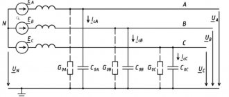
A ferroresonant circuit in a network with an isolated neutral is a zero-sequence circuit with a nonlinear magnetization characteristic. A three-phase grounded voltage transformer, by design, consists of three single-phase transformers connected in a star/star configuration with a separate magnetic system. During overvoltages in the network, the induction in the magnetic circuit increases by at least 1.73 times. In such modes, saturation of the magnetic circuit is possible and, as a consequence, the occurrence of ferroresonance in the network. According to energy supply services, every year 7–9% of voltage transformers are damaged in operation due to ferroresonance.
There are many ways to protect VTs from resonance phenomena in the network:
- production of VT with the most reduced working induction;
- inclusion of additional damping resistances in the HV and LV circuit;
- production of three-phase voltage transformers with a single magnetic system in a five-rod design;
- the use of special devices included in the open delta circuit;
- grounding the neutral of a three-phase voltage transformer through a current-limiting reactor;
- use of special compensation windings, etc.;
- the use of special relay circuits to protect the HV winding from overcurrents.
All these measures protect the voltage measuring transformer to one degree or another, but do not solve the problem fundamentally.
4.Zero sequence protection at higher harmonic currents.
Since the main disadvantage of protections using currents and voltages of NP industrial frequency is that they are not able to work in networks with a compensated neutral due to the lack of a stable useful signal of 50 Hz, protection against single-phase ground faults has been developed that respond to higher harmonics of electrical quantities. When arc faults occur, the content of higher harmonic components in the network increases sharply, especially in the current of the damaged line, where their share is significantly greater than in the zero-sequence currents of undamaged lines. These processes are observed in networks of all types of neutral grounding.
General disadvantages of devices made using higher harmonics :
| ! | — probability of failure to operate during short-circuit protection through transition resistances; — instability of the composition and level of higher harmonics in the NP current. |
The conditions for selectivity of non-operation in case of external faults and stability of operation in case of internal faults for devices for absolute measurement of higher harmonics are provided mainly at large substations and power plants with a large number of connections.
Consequences of OZZ
Despite the advantages of an isolated neutral, this operating mode has a number of disadvantages:
- Depending on the branching of the network, the capacitive current can range from 0.1 to 500 amperes. This amount of current can pose a danger to animals and people located near the fault; for this reason, these faults must be identified and turned off, just as is done in networks with a solidly grounded neutral.
- In most cases, an arc fault to ground occurs during a short-circuit fault, which can be intermittent. In this case, during an arc fault, overvoltages occur that exceed the rated phase voltage by 2-4 times. The insulation during the circuit may not withstand such overvoltages, as a result of which insulation breakdown may occur at any other point in the network and then the circuit develops into a double short circuit to ground.
- During the development and elimination of short-circuit faults, a ferroresonance effect occurs in voltage transformers, which with a high probability leads to their premature failure.
Despite the listed disadvantages, the OZ does not require immediate damage elimination. According to the PUE, in the event of an emergency, it is possible to operate the network without shutting down the accident for 4 hours, which are allocated to search for the damaged area.
Protection that responds to imposed current.
To increase the stability of the functioning of protections against single-phase ground faults that respond to a non-power-frequency fault current, a protection that responds to an imposed current was developed. The imposed current can be either higher or lower than industrial frequency. To create a high-frequency current, it is possible to use a nonlinear resistance connected between the network neutral and ground. However, this device significantly increases the cost of such protection and can reduce the reliability of the protection. You can also note the fact that a significant high-frequency component may be present in connection currents in normal mode. This primarily applies to networks associated with industries that have a nonlinear load. In such cases, the described method of protection is unsuitable. In addition, as some studies show, harmonics with a frequency of 100 Hz appear almost 2 times more often than, for example, with a frequency of 25 Hz and their amplitudes are much greater.
The main disadvantages of protections that respond to an imposed current with a frequency lower than the industrial frequency include the need to connect a special device in the network neutral to create a control current, the influence on the stability of the protection of CTNP errors, which increase with a decrease in the operating frequency, and the complication of the primary switching circuit due to the need to connect source of superimposed current and the difficulty of connecting an auxiliary current source when using several DGRs installed in different facilities in the network. difficulties cannot be ruled from natural harmonic components during external arc intermittent faults, in which the current spectrum depends on the parameters of the network and the grounding mode of its neutral , the position of the fault point in the network.
Protection based on a centralized principle does not have the disadvantages of individual protection, such as false alarms associated with transient processes on undamaged lines. In centralized protection, comparison of amplitude or effective values of zero-sequence currents is mainly used. The damaged feeder is determined by comparing the zero-sequence currents across all connections and selecting the connection with the maximum zero-sequence current. The calculation of these values can be carried out both at the initial moment of time, that is, based on the transient values of the closure, and in steady state. In addition, it is possible to use higher harmonic components of zero-sequence currents or superimposed current with a frequency different from the industrial one . To expand the scope of application at substations with a large number of connections, it is possible to introduce additional information into such protections , which allows you to tune out the action in some complex modes, for example, receiving information about the zero-sequence voltage from another section of the substation buses can increase sensitivity.
Grounded VTs
Grounded voltage transformers are used in networks with an isolated neutral. Grounding the VT neutral makes it possible to monitor the network insulation using additional secondary windings connected in a star/delta configuration. In our opinion, this is the main function of grounded transformers; the measurement and accounting function is additional. Often, grounded voltage transformers are used in electrical networks, in which protective windings are not used. The use of grounded transformers without using the network insulation control function is an unjustified risk.
This is due to the fact that:
- grounded voltage transformers are susceptible to ferroresonance phenomena;
- The insulation of the HV winding cannot be tested under operating conditions with an applied one-minute power frequency voltage.
2.Centralized protection with parallel polling of channels.
Through the use of microprocessor systems and special physical elements for relay protection devices, it has become possible to implement a parallel comparison of zero-sequence currents between each connection. The first such systems compared the amplitudes of transient currents, but later, as practice showed, these systems had false alarms due to asynchrony or out of phase of the compared signals, since the frequencies and phases of transient currents in damaged and undamaged connections may differ from each other.
3.Centralized protection with parallel synchronized polling of channels.
The next step in the development of protection against short-circuit faults required the development of protection devices operating in the mode of pulse comparison of zero-sequence currents in all connections, thereby eliminating the influence of out-of-phase and asynchronousness of the compared signals. One of such developments is Geum-type protection produced by NPP Microprocessor Technologies for networks with isolated (also capable of working with resistive-grounded neutral) and compensated (combined) neutral. The protection based on the principle of operation is a centralized current non-directional, comparing the amplitudes of surges of zero-sequence capacitive currents in all connections of the protected section at the moment of operation of the trigger element switched on to the zero-sequence voltage and determining the damaged connection by the largest amplitude. The response current of this protection does not need to be adjusted from the capacitive current of each of the protected connections, which significantly increases the sensitivity of the protection and thereby distinguishes it favorably from the previously described devices of non-directional zero-sequence current protection. Being an advanced development in identifying SPD, this protection, based only on a relative measurement algorithm, is not able to cover the entire variety of modes associated with processes affecting the operation of SPD protection, which are described above. Thus, additional algorithms were introduced into this protection.
Single-phase earth faults in 6-35 kV distribution networks - what is it? Consequences of OZZ
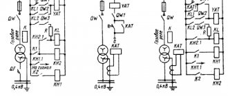
Arc suppression reactor
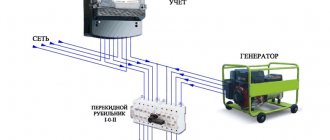
To limit capacitive currents, a special arc suppression reactor is introduced into the transformer neutral (Fig. 3).
Figure 3 – Arc suppression reactor
This method is the most effective means of protecting electrical equipment from ground faults and compensating for capacitive current. With its help, it is possible to reduce (compensate) the current of a single-phase ground fault that occurs immediately after an accident.