The assembly of any computer networks is not complete without the use of various types of connectors. The RJ45 model (Registered Jack - registered connector, type 45) is widely in demand in the household and industrial sphere. The unified clip is designed to simplify the connection of any equipment. Used to set up local or global network systems.
It is profitable to buy an Ethernet RJ45 connector in Moscow from AVS Electronics. Wide range of products at wholesale prices. Contact by phone +7.
Design features
Despite the variety of types of twisted pair sockets, their design is almost identical, with the exception of small details. As an example, let's look at a typical external single-port device.
Rice. 1. Basic elements of an external RJ-45 socket
Designations:
- A – plastic cover.
- B – base.
- C – functional board with a standard connector installed on it.
- D – convectors for connecting twisted pair cables.
- E – tie for fixing the cable.
- F – connector for connector.
Externally, the socket resembles an RJ-11 telephone standard; the main difference is the number of connector pins, there are eight of them, not four. Accordingly, a computer socket can be used as a telephone socket, but not vice versa.
Different types of devices may have minor characteristic features, but the overall design concept remains the same.
Twisted pair crimping circuits
During crimping, the cores should be in the following order:
Twisted pair crimp circuit
- light red (b-o) - b-o;
- red (o) - about;
- light green (b-z) - b-z;
- blue © - s;
- light blue (b-s) - b-s;
- green (h) - h;
- light brown (b-k) - b-k;
- brown (k) - k.
Types and characteristics
The main parameters of these switching devices are determined by the following criteria:
- Number of ports.
- Category.
- Execution.
Let's briefly talk about each of them.
More doesn't mean better.
One of the main parameters is the number of ports. As a rule, there can be from one to four. If you need to use a larger number of connections, it is easier to install a patch panel, but such a need indicates an ill-conceived network layout. In addition, it should be taken into account that a large number of patch cords connected nearby causes some inconvenience.
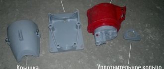
Rice. 2. Krauler 4-port external socket
In practice, when organizing an office or home LAN, one and two-unit modules are mainly used.
Category.
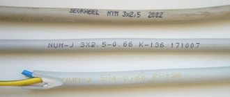
This parameter is directly related to the characteristics of the cable used to install the computer network. We are talking about bandwidth, which determines both the data transfer speed and the ability to use special network technologies. Below is a table that shows the relationship between category and bandwidth.
Dependence of cable technical parameters on its category
Currently, when installing a LAN, cables with a category lower than 5e are practically not used.
It should be taken into account that the category of the outlet must be no less than that of the cable being connected, otherwise there is a high probability of losses, which will negatively affect the transmission speed.
Execution.
The method of mounting the switching device depends on this parameter. There are two versions:
- for external (external) installation (such sockets are shown in Figures 1 and 2);
- for indoor installation.
Internal two-port RJ-45 socket disassembled and assembled
As a rule, the choice of one or another version depends on how the LAN wiring is done. If it is external (for example, laid in boxes), external sockets are used. In cases where hidden wiring is done, the internal devices look more aesthetically pleasing.
Separately, it is necessary to highlight the sockets that are installed directly on the box. Technically, such execution can be considered both internal and external.
Double RJ-45 socket mounted on a box
The technical characteristics of the LAN are not affected by the execution.
Modular designs.
Speaking about performance, we cannot fail to mention modular designs. This solution allows you to assemble a socket in a standard case for a specific combination, for example, install it in RJ-45 and RJ-11 modules or with different categories.
Modular socket
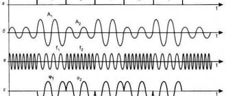
Seven Ethernet Frame Elements
- The first element, consisting of 7 bytes, is called the “preamble” and is used to synchronize the communication process between two network nodes, that is, between the sender and the recipient. To accomplish this task, adapters are used for the receiver on the one hand, and oscillators for the sender are used on the other: these two components essentially synchronize the clocks of the sending and receiving nodes.
- The second element is the SFD (Start Frame Delimiter) of 1 byte, which is used to determine the preamble boundary and the beginning of the data packet.
- The third and fourth elements of the Ethernet frame, each 6 bytes long, correspond to the destination and source MAC addresses, these are physical identification addresses uniquely assigned by the manufacturer of each network card and therefore uniquely associated with each node on the local network.
- Ethertype , 2 bytes in size, indicates the type of protocol used for communication. Depending on the case, IPv4 or IPv6, PPPoE and ARP can be used.
- Payload or "data field" - from 46 to 1500 bytes - contains the actual information in the message.
- To close a frame, an FCS (Frame Check Sequence) is used, consisting of 4 bytes containing a control value of the CRC (Cyclic Redundancy Check) type and allowing errors to be detected during data exchange.
RJ-45 pinout
There should be no problems with this, since opposite each contact group there is a color marking that complies with the T568A and T568B standards (can be marked with the letters “A” and “B”, as in the figure below).
Markings for the T568A standard are circled in red, T568B are circled in blue.
It doesn’t matter which standard is used, the main thing is that it is the same type for the LAN, otherwise problems are guaranteed. It is believed that we have adopted a “crimp” type T568B, but this is a rather conditional statement.
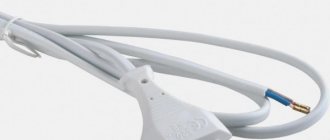
If you do not know which standard your provider uses, then you can install it using the pinout of the connector installed on the cable entering the apartment.
RJ-45 connector pinout
Basic mistakes
Unwinding of the twisted pair by more than 13 mm is not allowed.
Installation of the rg 45 socket is not difficult if done carefully. But there are a number of mistakes that experts make more often than others.
- Failure to comply with connection standards. If the device does not work and problems appear, you need to check compliance with the labeling. This is the most common mistake and solves about 90% of connection problems.
- Cutting off the cores before closing the lid. If you cut off excess parts before the cover has been installed, the wires may fall out. In this case, you will have to repeat the installation procedure.
- Stripping of insulation more than 13 mm. Large uninsulated parts of the cores lead to a drop in transmission speed and deterioration in signal quality.
Installing an Internet outlet yourself is not difficult. It is only important to follow the connection instructions and follow all steps carefully and carefully.
Detailed connection instructions
Let's start with the tool that you will need to seal twisted pair sockets. Ideally, it is advisable to purchase a universal extractor (shown in Figure 9). It allows you to press and cut the rest of the wire in one movement. Thanks to Chinese manufacturers, such a universal tool costs about 3-4 dollars. The price of branded products can be 2-3 times more expensive.
Rice. 9. Universal extractor
This tool has a special mechanism that allows you to press the wire between two contact knives and cut off its excess (3 in Fig. 9). In addition, it is equipped with a flat screwdriver (2) and a hook (1), which allows you to remove the wire if it is incorrectly terminated. The cost of a universal extractor is relatively low, but the benefits are quite tangible.
No less useful are universal insulation stripping pliers. They cost about the same as an extractor and can cut Ø3.5-9 mm cables such as UTP, STP, FTP. It is possible to adjust the depth of the cut.
Universal stripping pliers
It is not advisable to use a knife to strip the insulation, since in this case there is a high probability of damaging one of the twisted pair wires.
Having dealt with the necessary tools, let's move on to the algorithm for embedding a twisted pair cable into a switching device. We will assume that the cable has already been laid and the outlet space has been prepared. The procedure is as follows:
- Using universal pliers, cut off the outer insulation layer from the end of the wire. It is enough to expose 4-5 centimeters. You need to act carefully so as not to damage the wires. If this happens, trim the damaged area, adjust the depth of the cut and repeat the operation.
- After removing the insulation, level each pair. Please note that there is no need to clean them. Each pad contact has special micro knives that cut the insulation and ensure reliable contact and fixation of the wire.
- We disassemble the socket. To do this, remove the front panel. To do this, you will need to unscrew the fixing screw or unfasten special latches (depending on the design). If you are using a modular socket, you will need to remove the modules from it.
- We fix the cable on the module using a tie (E in Fig. 1) or another method provided by the design.
- We insert the wires into the clamps, and it is necessary to adhere to the color markings of the selected standard. Do not try to recess the veins deeply; it is enough to simply fix them with a little force (A Fig. 11).
- Using an extractor, we perform pressing (B in Fig. 11).
Rice.
11. A – cable with wires routed through clamps, B – pressing with an extractor. At this stage, we will make a small digression regarding the use of improvised means for pressing. Sometimes you can find advice in which, in the absence of the necessary tool for pressing, it is recommended to use a utility knife or a thin slotted screwdriver. This approach can only be used as a last resort, when access to the network is urgently needed, but there is no tool at hand. But in the future, such a socket must be clamped. Otherwise, there is a high probability of losing contact between the wire and the latch after some time.
We also note that many branded manufacturers include a simple plastic extractor for each socket, which allows you to securely seal the wire, after which all that remains is to carefully trim off the excess.
- After pressing, the module is installed in place. If the socket is external, then its base is screwed to the prepared area, so that the cable is supplied from above, and the connector is from below. When installing an internal socket, its base is installed in a prepared glass and fixed in it.
- We fasten the front panel and then check its functionality. This can be done using a special tester, but it’s easier to connect a computer and check for a network connection. If problems arise, first of all check the correctness of the pinout; as practice shows, in 90% of cases the reason lies precisely in this.
Some useful tips
When using a shielded cable, you must install an appropriate socket that has a shield connection. Otherwise, it turns into a large antenna, which will immediately affect the bandwidth, and, consequently, the data transfer speed. For the same reason, you should not use an STP or FTP cable if ungrounded equipment is connected to it.
Twisted pair LAN technology requires the use of continuous lines. Twists and adhesions are unacceptable; this leads to serious losses. If it becomes necessary to extend a piece of cable, special connectors should be used for this purpose.
Rice. 12. Twisted pair connectors
These devices are a box in which a board is installed with two RJ-45 connectors (A in Fig. 12), or twisted pair clamps, like sockets (B in Fig. 12).
It is not recommended to use sockets with more than two ports in domestic conditions. A large number of patch cords in one place will cause them to become tangled. It is better to space the sockets some distance apart.
History of Ethernet Cable
All of the physical and protocol elements that serve to technically define Ethernet were experimentally designed by Robert Metcalf between 1973 and 1974 at Xerox PARC (Palo Alto Research Center). The latter was inspired by ALOHAnet , a network protocol whose purpose was to guarantee access and data transfer functions in small networks.
The name Ethernet was first used in May 1973 by Metcalf himself, who was trying to convince Xerox executives of the importance of his work. The name was chosen to "pay homage" to the luminiferous ether, a gaseous and intangible substance that in the mid-19th century was considered an inert medium through which electromagnetic waves propagated. In 1975, Xerox filed a patent on behalf of Metcalfe and his team (in addition to David Boggs, the patent bears the names of Chuck Tucker and Butler Lampson).
The technologies described in the patent were successfully used at Xerox PARC, and in 1976, Metcalf and Boggs published a scientific paper, "Ethernet: Distributed Packet Switching for Local Computer Networks," in which they described the fundamental parts and operation of a network based on Ethernet technology.
In 1979, Metcalfe left Xerox, but was still able to convince the then American IT giant to enter into a partnership with Digital Equipment Corporation and Intel to begin work on a unique Ethernet standard. Thus was born the DIX team (from the initials of the three companies involved in the project), which the following year presented the first proposal for Ethernet standardization in the field of LAN IEEE This first proposal was for a 10 Mbps standard with 48-bit addresses: 10BASE-T , the “base model” of Ethernet connectivity.