Electrical sockets for 380 volts are used in enterprises and construction, as well as in private homes, cottages or garages to connect welding machines, engines, compressors and equipment requiring three-phase voltage. In most cases, three-phase sockets are used to supply voltage to powerful electrical equipment. Such sockets are rarely found in apartments, but modern manufacturers strive to produce powerful equipment for the home. One condition is that there must be three-phase wiring in the room.
Basic principles of connection
Connecting a three-phase socket consists of connecting 4 (without a grounding conductor) or 5 conductors, three of which will be phase, the fourth will be neutral, and the fifth (if any) will be ground. When purchasing an outlet, you need to know whether the plug on the appliance will fit into it. If not, then it’s better to buy a plug (you can change it on the equipment).
Before starting work with a voltage indicator, it is necessary to determine where the phases, neutral and ground are located on the supply cable. It is important not to mix it up, since connecting a phase to the zero or ground terminal will result in equipment breakdown and electric shock to a person. Then turn off the supply voltage and check that it is missing using a tester.
After all the work has been carried out, you should turn on the power supply, make sure that there is no phase on the case, measure the voltage between the phases - it should be 380 V. The socket is connected correctly if all conditions are met.
Three-phase socket: features and connection
More recently, electricity consumption in apartments and private houses was very modest, and three phases were not necessary. But modern home ownership requires a completely different level of energy consumption. In this regard, the idea of using three-phase input into the house is becoming popular. In some cases, you can no longer do without it. If the house is heated with electricity, you will need a 3-phase boiler, but it is not produced in a single-phase version. In addition, three-phase electric stoves, boilers, as well as electric motors of machine tools are also used. The power of consumers is not as large as that of industrial ones; the connection is made using a socket.
Types of three-phase connectors
There are 380 volt sockets: four-pin - PC 32 and five-pin - 3P+PE+N. They differ in the connection diagram and the number of plug sockets. The circuit diagram of a 380 volt 4-pin socket is the same as that of a five-pin socket, the only thing is that the grounding is not connected to the connector, but directly to the body of the electrical equipment, and therefore it is used only for stationary equipment. Five-pin - used for moving installations, and a plug connected to a flexible copper wire is connected to them.
There are also imported sockets, but they are more expensive than domestic ones. Their use is determined by design requirements or the presence of a corresponding plug in the device.
Another important point of difference between sockets is the specific current for which they are designed. It is necessary that this value exceeds the maximum current of the connected electrical equipment.
Also, 32a contact sockets are divided according to the installation method into internal and external. Internal versions are in great demand because they are easy to use, but their installation requires additional labor, namely: drilling a hole in the wall for the socket box, securing it with alabaster and mounting the socket in the installation box.
How to connect a three-phase socket
After considering the theory, you can move on to direct practical actions. It is recommended to consider the standard connection of a three-phase outlet using the example of a typical power device. This socket is equipped with a protective cover and is used for external installation on wall surfaces. Regardless of the manufacturer, they are all standard and connect in the same ways. Three-phase power connectors are used not only with industrial equipment, but also at home to connect water heaters, electric boilers, fan heaters and other powerful devices.
Socket 3P+PE+N
If you need to connect mobile electrical equipment, for example, a welding inverter, compressor, machine tool, it is recommended to use a 380 volt socket 5 contacts 3P+PE+N. This is usually needed in workshops, car garages and construction sites. How to connect this device?
First you need to disassemble the socket to get to the screw terminals. In this case there will be five of them. According to the connection diagram for a 380 volt socket, connect one of the three phases in free order to the terminals marked as L1, L2, L3. The phase sequence only affects whether the motor rotates clockwise or counterclockwise. If it later turns out that the rotor is not spinning in the direction required, it will be possible to swap any two phases on the switch or on the starter. A zero is connected to the terminal labeled N. It should be noted that the plug also has a mirror contact zero, it is necessary to combine them. The pin marked PE or the ground symbol is where the conductor connected to the protective ground loop is connected. The PE socket is located near the guide recess, which prevents the plug from being inserted into the socket by mistake.
Types of sockets
Power connections differ in shape, method of fastening and number of contacts. The socket can have from 3 to 5 connections. To understand the difference, it is important to study the operating principle. In the CIS countries, a three-phase network with a voltage of 380V is used. A standard apartment uses 220V. This indicator can be obtained by connecting one of the three phases to the neutral wire. To connect a 380-volt industrial outlet, it is enough to combine two phases and a neutral wire. A conventional electric stove has a similar connection principle.
There are several standards for power connectors:
- 2P+PE - two phases and one grounded contact are used;
- 3P+PE - 3 power cables and one grounded;
- 3P+PE+N - 3 phases, one ground and zero;
- 3P+N - three power contacts and one neutral.
Socket 380V 2P+PE Socket 380 3P+PE
Socket 3P+PE+N
Plug 380 3P+N
Switching connections differ not only in the number of contacts, but also in the structure of the housing. There are cable structures that serve to connect portable devices. Flange switches are manufactured with a mount that can be built into the wall directly or at an angle. The last type is overhead sockets. Some cases are equipped with an additional protective cap.
Marking
The letter P indicates the power or phase wire, N stands for neutral, and the designation PE indicates the grounding cable. The wires are also color coded. Electrical installation rules require that the phase be designated in burgundy, red or brown, and zero in blue or a light blue tint. The earth is painted in two colors - yellow and green.
In addition to the voltage, the maximum permissible current is indicated on the case. An industrial 380V socket can withstand 16A, which is acceptable for a regular network. For more powerful ones, connections of 32, 63 and 125 amperes are used. To avoid overheating and fire, it is important to check the electrical current strength in advance.
The marking may also indicate the degree of protection. IP44 indicates that the outlet insulates electrically conductive areas from splashing water and dust particles. Often such cases are equipped with overhead protection.
The IP64 marking implies a completely sealed housing. Maximum protection allows connections to be made indoors or in open spaces with high humidity.
PC32a socket
When you need to connect stationary equipment to electricity (always located in one place), for example, an electric stove, a 380 volt 32a socket is suitable. Three phases are connected to the three terminals of the socket L1, L2, L3, and working zero is connected to N. There are modifications with four contacts, but this does not mean that protective grounding is not required, it is simply connected directly to the metal part of the electrical device housing. According to electrical safety rules, permanent grounding is connected to stationary equipment, bypassing the socket and cord made of copper multicore cable without insulation (for visual assessment of its integrity). The thickness of this cord should be no thinner than the diameter of the supply wire core.
Features of the 380V outlet
Takel Power Socket Fixed Internal 380 Volt
Power cable connectors are designed for harsh technical conditions. The industrial plug and heavy-duty 380V socket are protected by a durable housing that can withstand minor impacts. Simplicity of connection, strong plastic and high throughput allow the connection structure to be used outdoors, in industrial workshops or during construction work. The product is subject to increased safety requirements.
The contacts have a large contact area, which reduces the load and eliminates possible overheating. Each cable clamp is secured with a screw connection that holds the wire in its seat. The copper construction is protected from corrosion and is also resistant to oxide film growth.
The clamp holds the cable securely, preventing breakage. Special grooves ensure a strong connection and eliminate backlash. The contacts have different diameters and are located at their own angles. The connection provides protection against unbalanced connection, which prevents short circuits.
With high voltage, the risk of arcing increases. Each 380 socket has mechanical or automatic protection. The device can stop power supply until removed. The solution reduces the risk of equipment failure or skin burns.
The plastic is resistant to overheating, non-flammable and can withstand direct sunlight. Protection from dust and moisture is provided, which will preserve the quality of parts and make work safe.
The 380 volt electrical outlet is manufactured in accordance with the IP 44 or IP67 standard.
Outdated connection method
In the past, it was possible to connect the phase and neutral wires to the outlet terminals in any order, and this did not adversely affect the performance of electrical equipment manufactured using the TN-C system. The only thing was that it made it inconvenient for repairmen when troubleshooting. Today, electrical equipment is produced that is sensitive to incorrect connection of phases and zero, so it is important not to make a mistake when connecting, otherwise a malfunction and emergency situation may occur.
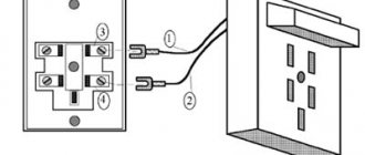
In Soviet times, four-wire wiring was used, including three phases and zero. Three-phase stationary type sockets were connected, which were marked with phase and zero symbols (zero was signed with a grounding symbol) on the forward and reverse sides. The same markings were on the fork. These four-pin plugs and sockets are still used today, connected as TN-C, grounded only and using a five-conductor power cable. Where three wires will be - three phases, the fourth - zero, and the fifth - grounding.
Plug-in connections for a five-wire network
In this system, the connection design becomes more complex, and the safety of use is significantly increased.
Electrical circuit diagram
The body of the electrical device is securely connected to the neutral of the supply transformer through the fifth wire, called the PE conductor, and an RCD is added to the protection structure.
When the insulation breaks down between the potential of any phase and the housing, a leakage current is created through the PE conductor, which is immediately detected by the differential organ of the RCD, and it automatically turns off the power, eliminating the risk of electrical injury.
Detachable connection design
One more contact has been added to the numerous types of connectors for a three-phase network with five wires.
In this design, the cable cores are switched according to the previous method, but the structure of their designations has changed to the modern European standard.
Wire connection methods
To mark the phases, the first letter of the English word “Line” is used and they are numbered in Arabic letters. As a result we have:
- L1;
- L2;
- L3.
The designation of the working zero is marked with the letter “N”, indicating “neutral wire”, and the protective zero is marked with a grounding symbol.
Most designs use a screw connection with washers for connecting wires. But this is not the only method.
Screwless wire connection
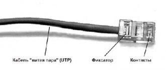
Manufacturers of modern connectors for three-phase networks, constantly improving their products, have developed a convenient and safe installation technology based on creating electrical contact with the wire core by cutting through its insulation layer with a special knife with fixation.
The sequence of the wizard’s work is shown in four photographs:
- No. 1 - bringing an insulated and unstripped core to the connection socket;
- No. 2 - pushing the end of the core deep into the hole until it stops;
- No. 3 - installation of a flat screwdriver tip into the socket;
- No. 4 - lifting its handle up to the stop, which ensures a puncture of the dielectric layer and the creation of a tight electrical contact through the knife blade.
The worker can only verify the strength of the created mechanical connection and the reliability of holding the core inside the socket.
Screw method of fastening the cores to the socket
In order to connect the conductors to the connector, you need to use one of the mounting options. The screw method is time-tested and very reliable. On the back of the socket there are screw terminals into which the ends of the cable are inserted and screwed to the contact. Before this, it is necessary to prepare the veins. Clean them with a sharp knife or a special tool for carefully removing insulation - a stripper. Put on the sleeve tips and crimp them with a hand tool - a crimper. If you don't have crimping pliers on hand, you can use a soldering iron and tin the twisted wires. Thus, the treated ends of the cable can already be screwed to the socket.
Marking and electrical parameters
Waterproof outdoor socket
The main technical characteristics are indicated in the passport and on the socket body. These include: manufacturer's logo, degree of protection, type of current, maximum current and voltage. An example of a designation on the body is shown in Fig. below.
Marking on the case from the manufacturer Legrad
The passport contains technical data in more detail: manufacturer, product grade, compliance with GOST. The applied markings must be easy to read.
List of parameters that must be indicated in the connector passport:
- Operating voltage range – 380-415 V volts;
- Allowable current – ХА;
- Operating frequency of the network – X Hz;
- Location of the grounding contact – h x;
- Operating temperature – from –40 °C to +50 °C;
- Protection – IPхх.
On the connector body its characteristics are indicated with an 8-bit code, for example:
X1 X2 X3–X4 A X5 Х6 AC X7–X8
Decoding the connector code:
- X1 – indicates the type of product and takes the following values:
- 0 – if the plug is for the cable (portable),
- 1 – overhead socket (for outdoor installation),
- 2 – socket for cable,
- 3 – socket with flange,
- 4 – socket for outdoor installation, flanged,
- 5 – plug for outdoor installation,
- 6 – plug with flange.
- X2 – current limit:
- 1 – at 16A,
- 2 – at 32A,
- 3 – at 63A,
- 4 – at 125A.
- X3 – number of electrical contacts:
- 3 – 3 contacts,
- 4 – 4 the same,
- 5 – 5 the same.
- X4 – maximum current, X A;
- X5 – location of the grounding contact, 0h – 12h;
- X6 – operating rated voltage;
- X7 – correspondence of electrical contact designations:
- 2P + PE – 3 pin,
- 3P +N – three and common,
- 3P + N + PE – 5 pin.
- X8 – protection index, IP =00 – 68.
For example, one of the options is a socket with the designation 113-16A-6h-220AC-2P+PE-IP44, which stands for: external, 3-phase, 16 A, ground contact position 6h conventionally shows the clockwise position, single-phase, contact designation P – (phase) phase, N – (neutral) neutral and E – (Earth) earth, 44th degree of protection, for surface mounting.
Position X5 shows where the N contact is located in relation to the others. In Fig. Below are options for the location of the N contact, depending on the type of connector.
N contact location
Position X8 indicates the level of protection of the connector from the external environment. According to GOST 14254-96, the level of protection is designated as IP - this is an abbreviation for International Protectio, that is, internal protection consists of two categories. The first indicates the level of protection of the connector from dust particles. The second is the level of protection against moisture penetration, that is, it is protection from most atmospheric influences: moisture, snow, rain. They negatively affect contacts, especially outdoors. Protective methods are aimed at meeting safety requirements. In Fig. The degrees of protection of the connectors are shown below.
According to the international standard, cases are available in different colors, depending on their purpose.
By the color of the connector body you can determine what electrical parameters it is made for:
- l Yellow – for frequency 50 and 60 Hz and U = 100-130 V;
- l Violet – U = 20-25 V;
- l White – U = 40 – 50 V;
- l Blue – U = 200 to 250 V;
- l Orange – U =125 to 250 V;
- l Red – U = 380 to 480 V;
- l Black – U = 500 to 690 V;
- l Gray – U = 277 V, but 2 poles;
- l Green – for f above frequency 60 Hz and voltage above 50 V.
The most commonly used color is red for 380V and above, blue for up to 220V.
Screwless mounting method
This is the most modern and convenient connection because it saves the electrician’s time, reduces labor costs and allows you to correct a connection error.
First, the cable is stripped, if necessary. For your information, sockets are produced where the insulation does not need to be removed; it is pierced with a special sharp clamp. The wire is then placed into the socket according to the 380 volt outlet diagram. The next step is to simultaneously press the lever and push the wire under the clamp, and then you just need to release the handle to fix the wire. Then you need to check the strength of the connection by pulling the cable.
There is a modification of the sockets, where instead of levers on each contact there are holes for a flat-head screwdriver. Then, placing the wire in the socket, insert a flat-blade screwdriver into the groove, and then lift the handle of the tool up. At this moment, the insulation will cut through. All that remains is to remove the screwdriver and check the strength of the contact by tugging on the cable.
Crimping an external socket
If your apartment or office has already been renovated, you will have to use external sockets. They cost a little less than previous options. The only drawback is that you will have to additionally run the cable through a special cable channel.
We unscrew the socket and see two crimping patterns: 568A and 568B. We will crimp according to the “B” pattern - we look at the very left and right sides. Scheme according to the picture:
- Left: White and orange.
- Orange.
- White-green.
- Green.
- White and blue.
The knives here are open and not slammed shut by anything. Now the question arises: how to compress this Internet socket? For this we need a special network cross-knife.
If you don’t have one, you can use a stationery or construction knife. We simply insert the wire into the groove and press it a little from above so that it fits into the knife. Once you have managed to connect the socket and wires together, you can assemble it and screw it to the wall.
Connection diagrams
The connection plan differs for different types of 380 V sockets. The characteristics and connections also vary. The diagram of a five-pin socket has already been discussed above; now it is proposed to take a closer look at connecting 4 pins.
The types of old types of sockets can be quite successfully used in a modern five-wire wiring system using TN-S grounding. In this scheme, protection against leakage current is provided by the PE ground wire, which is connected to the central PE ground busbar. This conductor is connected directly to the electrically conductive part of the equipment body, and not to the grounding contact of the outlet, which is missing in this case.
Naturally, a three-phase device must be stationary so as not to reconnect the ground.
Instrument layout
Next, for proper wiring, a floor plan is drawn, and the locations of sockets, switches, and other electrical wiring elements are marked on it.
It is important to decide at this stage where the stove, cabinets, sofas, armchairs, tables, refrigerator, dishwasher, and other household appliances will be located. Number of sockets – one per 6 m2, or more, to connect the necessary equipment (in the kitchen)
The number of sockets is one per 6 m2, or more, to connect the necessary equipment (in the kitchen).
However, wiring in a private house or modern apartment occurs not by room, but by group of devices:
- sockets for living rooms;
- sockets for powerful appliances, which are often located in the kitchen;
- lighting (it can be divided into parts of the apartment);
- connecting particularly dangerous devices (warm floors, bathroom appliances);
- connecting devices in utility rooms (garage, basement, workshop).
This type of wiring is the most popular for a private home. For each group I install my own RCDs and circuit breakers. Wiring into groups further simplifies repairs, replacing light bulbs and other work.
To indicate wiring groups on the plan, you must use different colors. Sockets can be external (the housing protrudes from the wall) or internal (the electrical part is located in a special recess, easily correlated with the color of the finish). They also need to be marked differently on the wiring plan.
Based on the floor plan, a wiring diagram is drawn up, on which the wiring will be visible. It can be of three types: sequential, parallel or mixed.
The latter has such advantages as: versatility, savings in materials and components, high efficiency. For a private home, it is best to choose it.
The finished wiring diagram for a wooden house should contain the most complete information about the future system.
The total power of the electrical network is calculated, and 20-25% of the reserve is added to it. The planned load on electrical wiring is calculated by the formula: the total power of household appliances (W) divided by the mains voltage (V). The standard indicator for a private house is 20-25 (A).
It is important to save the electrical wiring plan (+ photo) for future optimization/repair of the electrical wiring of a private home. They are easy to determine if you need to drill or pierce a wall
Voltage check
To make sure that the 380-volt socket is connected accurately, it is recommended to use a multimeter turned on in the AC voltage measurement mode and use the diagram.
Between phases in free sequence a value of 380 V should be observed. Between zero and each phase separately - 220 volts, and also between grounding (protective zero) and each phase - also 220 volts.
Only when all the values match can you start using the outlet to power electrical installations. In the event of a malfunction of energy consumers, the socket will perform the function of protection against electric shock.
There is another way to protect against current leakage - this is a special device called an RCD (residual current device). It is connected immediately after the power supply, and behind it there is a cable to the outlet. It will turn off as soon as a leak appears in the circuit and thereby prevent electric shock to a person.
By installing a differential circuit breaker, you can replace two devices - a power supply circuit breaker and an RCD, since it performs the functions of these elements of the electrical circuit. Usually, when from previous times only a circuit breaker is present in the wiring, specialists replace it with a differential circuit breaker and all issues with protection are resolved.
Protecting connected devices
Connection diagram for a three-phase consumer using a socket and a circuit breaker
The protection device, in its ability to disconnect the protected section of the network, must correspond to the value of the short circuit current (maximum value) at the beginning of this circuit. The current of the fuse link and the setting of the circuit breaker are selected based on the minimum value of the short-circuit current or the current of the protected equipment.
The multiplicity of the short-circuit current in relation to the rated current for various protection devices must correspond to the following values:
All distribution boards must perform 3 main tasks:
For this purpose, automatic switches are installed in switchboards. They are primarily designed to protect the cable, and not the equipment connected to it, as many still think.
In case of overloads or overheating, the thermal release is activated and protects the wiring insulation from melting. In the event of an obvious short circuit, it is no longer the thermal, but the electromagnetic release that is triggered.
This is ensured by installing RCDs or differential circuit breakers.
Unfortunately, power surges often occur in our networks. The machines do not react to this, since they are simply not designed for such protection.
The RCD is also not designed to be triggered by overvoltage. To do this, you will need modular voltage relays or UZM - multifunctional protection devices.
They set certain upper and lower voltage limits. As soon as there is a jump, or, conversely, a sharp decrease in the parameters of the electrical network, this relay (UZM) is triggered and turns off the power.
What is the difference between assembling a 3-phase shield, in order to ensure the above tasks, from assembling a single-phase one? It is clear that single-phase is an order of magnitude simpler than three-phase.
There is only a single phase, zero and protective ground. In 3-phase, the same zero, protective grounding and already 3 phases come to your shield.
On the one hand, this gives you the opportunity to connect a much larger load and receive more power from the energy transmission organization for connection. But on the other hand, this always incurs high costs, plus the need for competent distribution of this very load.
You cannot (at least it will not be correct) connect all the devices in the house to one phase, and keep the other two as a reserve. This threatens the load imbalance between phases.
Advice from experienced electricians
In this case, the power of the devices may be different, which will cause the appearance of equalizing current in the neutral conductor, but the voltage on each of the electrical devices will be constant (with the exception of losses in the supply cables).
Expert opinion
It-Technology, Electrical power and electronics specialist
Ask questions to the “Specialist for modernization of energy generation systems”
Power sockets SSI-125 All household consumers are powered by four wires from a three-phase network, three phase linear L1, L2 and L3 and one neutral neutral conductor N, and single-phase voltage is supplied to the apartments, which requires only two conductors, neutral and phase. Ask, I'm in touch!
Checking the plug connection
If everything is clear with the question of how to connect a 380-volt outlet, then how to check the connection of the plug in the case when it has also been changed. You should use the multimeter again, but put it in resistance measurement mode. The plug does not need to be plugged into the outlet yet.
The resistance of the electric motor windings is measured through the plug contacts. In other words, the resistance between zero and each phase contact is measured. All three values must coincide with each other, and be equal to a specific number, for example R.
Next, the series resistance of the two windings is measured. Simply put, the resistance between two phase contacts is measured in any order. You should get three identical values, twice as large (than in the first case), that is, 2R.
If all measurements meet the requirements, then the plug is connected correctly and can be safely inserted into the outlet.
The plug and socket are designed in such a way as to ensure normal operation of transmitting the rated current of the consumer or opening the circuit, but only after the power supply has been turned off. They should not be used to interrupt the supply of voltage to avoid the occurrence of an electric arc or spark. To turn off the electrical installation, first turn off the power supply and then unplug the plug from the socket. To turn it on, first plug the plug into the socket and then turn on the machine. The same sequence must be followed even in an emergency.
Methods for checking the correct connection of a three-phase outlet
The work is carried out in four stages:
- an external inspection evaluates the condition of installation and the strength of the mechanical assembly;
- before applying voltage, the insulation strength of the assembled installation is measured with a megohmmeter;
- in ohmmeter mode, circuits are called from the switch contacts to the socket to determine their compliance with the circuit and the absence of the possibility of creating a short circuit;
- turning on the voltage at idle speed in order to measure its linear and phase values.
If connected correctly, we will measure 380 volts between the phases and 220 - relative to the phase wires with working and protective zeros. If this condition is not met, then you should look for an error in the circuit.
Advice from experienced electricians
Three-phase sockets must be carefully selected and installed. It is necessary to be guided by several basic points. The first is current strength. There are three types - 16, 32 and 64 A, respectively. The required one is selected based on the planned load.
The protection class shows the degree of resistance of the outlet to humidity, dust, and dirt. IP mark and numbers - the higher the value, the better, especially if there is moisture in the premises: bathrooms, bathhouses, etc.
An additional point is the installation method. The socket can be mounted on the wall (overhead) or a separate socket can be made (hidden). However, the type of device differs significantly.
We correctly connect to the input device
First of all, let's deal with color coding. The power cable for three-phase connection may have European colors, or comply with the Electrical Installation Rules. In the first case, the phases are marked with brown, white (gray) and black shell colors. In the second - (which is unlikely for residential buildings), yellow, green and red. The cables have one thing in common: just like in a single-phase system, the working zero will be blue (blue), and the protective ground will be yellow with a green stripe along the length of the wire.
After the three-phase meter (electricity meter), a four-way automatic machine must be installed. It is on line 4: since both phases and zero must be turned off if necessary.
Important! The protective grounding is inserted into the socket without the possibility of it being broken by the switching device (automatic machine)!
In principle, the binding of specific lines to contact numbers is not defined by any instructions. Each user himself determines exactly how to connect a three-phase outlet.
According to unspoken rules, on a four-pin socket (for example), the working zero is located on the right.
And on the 5-pin (with protective grounding) in the center.
For an outdoor outlet protected from dust and moisture, there is also a standard line layout.
And yet, three-phase consumers are connected to the power point individually; there can be no universality. If you are commissioning an electric stove, there are several power supply options on the input connection block: 220 or 400 volts.
By default, jumpers may be installed that will lead to a short circuit between phases. Therefore, you should first study the instructions for the electrical installation, and then plan the location of the contacts in the outlet.
Installations with three-phase electric motors have their own power supply. Again, we return to the basic rule: no universality.