Residual current devices have recently come into widespread use due to the increased number of household appliances. But residents do not always want to connect the entire apartment to this equipment due to possible false alarms.
That is why a regular socket with an RCD is popular, into which you can connect only one potentially dangerous device: a washing machine, a shower stall, a dishwasher. You will learn everything about the principle of operation, design features and types of protection devices from our article. Here you will find valuable installation tips.
Relevance of electrical sockets with RCD
More than 40% of fires occur due to faulty electrical wiring, and thousands of people a year die at home from electric shock. These sad cases might not have happened if the electrical circuit had been under the control of an RCD - a residual current device.
This device monitors the difference between the zero and phase currents, and if there is a significant difference, it turns off the power supply to the load.
The current threshold for human muscles not to let go of the wire is 10 mA, so the socket with an RCD must ensure a clear determination of its level and triggering of the protection. The automation of the device is designed in such a way that when touching a bare live wire, a person does not even have time to feel the electric shock - the device turns off the power supply almost instantly.
When installing an RCD in a house, you need to be sure that there are no current leaks inside the walls, otherwise the device simply will not turn on.
A breakdown of faulty wiring inside walls can be invisible for a long time and not lead to a fire hazard. But over time, the wire insulation becomes thinner and the current increases, which can cause a fire. The RCD detects the problem long before the cable heats up and disconnects it from the network.
If there is a hidden breakdown of insulation inside the walls, the user’s wallet also suffers. After all, in fact, electricity is spent on heating concrete slabs and plaster. Therefore, installing an RCD is an excellent way to increase the electrical safety of housing and its residents, as well as prevent unnecessary costs for paying for electricity.
Connecting an RCD in a three-phase network
Protection of devices powered by three phases at once is carried out according to a similar principle, with the difference that the RCD is selected for four outputs. An example of connection is shown in the figure below:
Rice. 5: Connecting an RCD in a three-phase system
As you can see, in this case, the protective device is also connected after the electric meter and the introductory packet. Individual circuit breakers that respond to phase short circuits are already connected behind it, and, if necessary, more sensitive RCDs are connected to create selective operation for certain groups of consumers.
Since installing a separate device for each phase is too expensive, group RCDs are used in three-phase circuits, which work with all elements of the line at once.
Internal diagram of the device
The residual current device is based on a differential transformer, which is a toroidal core with windings. It is he who is responsible for determining the leakage current, the occurrence of which leads to the operation of the electromagnetic relay.
The active load should be turned off within a maximum of 30 ms, although there are models that are designed for a threshold value of 10 ms.
For domestic purposes, sockets with an electromechanical RCD are produced, which does not require additional power to operate.
The RCD device for the socket has a special design that allows all equipment to fit into a standard socket box. Miniaturization of components also affects the cost: if you purchase the components of the device separately, their price will be at least three times lower.
What types of RCDs are there?
The main classification of residual current devices is based on their operating current. For example, fire protection devices respond to currents of 100, 300 and 500 mA. They protect wiring from fire in the event of insulation failure and short circuit. Typically, an introductory RCD is installed behind the electric meter and provides protection for the entire facility. For people, electric current becomes dangerous at 50 mA. Therefore, devices that protect against fire are not able to protect a person from electric shock. For these purposes, devices are used that turn off the network when the current reaches a value of 10 or 30 mA.
Protective devices differ in the number of poles and can be used in single- or three-phase networks. Each type of device has a different way of functioning. The markings on the body of the device must be correctly deciphered and you need to know exactly what it means:
- AC is a category of RCD used only in alternating current networks. Accordingly, the device responds only to alternating current.
- A - protective devices of this category operate not only with alternating current, but also with direct current.
- B – has more advanced functions and responds to three types of current. In addition to direct and alternating current, the device turns off with rectified differential current.
- S – selective devices with the possibility of time delay when switching off.
- G – are also selective devices, but with a shorter time delay.
RCDs are also classified according to their technical design. This allows you to select a RCD of better quality. Most often, electromechanical devices are used that do not have their own power supply. They operate and shut down when a differential current appears.
Another type refers to electronic protective devices that require connection to an external power source. In this regard, the reliability of protection decreases, so such RCDs are used less frequently. When the auxiliary power is turned off, they turn off the network automatically, and when the power is restored, the network also turns on automatically. Some device designs do not provide for automatic switching on of the circuit when the power supply is restored.
Possible design options
In the combination of a socket and an RCD, both devices are equivalent. It is difficult to determine the main role of any of them. Therefore, externally they can look like a socket with an RCD or an RCD with a socket.
The protective adapter is attractive due to its low price and ease of use. It can always be moved to another room to connect the desired device
The design of these devices can be as follows:
- module built into a socket box;
- monoblock adapter inserted into a simple socket;
- module mounted on a DIN rail.
In fact, these devices are two independent devices connected within one design. Their functionality is the same, so the main selection criterion is the convenience of one or another model in a particular situation.
Types of residual current devices
Each device processes a flow with a certain fluctuation and nominal value.
The parameters are indicated on the device body. In addition to the maximum possible passing current, RCDs are divided according to characteristics :
- number of poles;
- installation method;
- operating voltage.
The number of poles corresponds to the number of conductors. There is an RCD with four terminals for working with a three-wire or two-wire highway. The device is mounted permanently or portable options are used. For a single-phase network, devices are produced for 220V , for a three-phase network - 400V .
Electromechanical
It always works if there is a loss of electricity in the area, regardless of the presence of voltage.
Features of the electromechanical device:
- the main unit is a differential electromagnetic transformer in the form of a core with wound windings;
- losses of electricity in the area cause voltage to appear on the secondary winding, the relay and machine are activated;
- To connect to the network, you need to study the electrical connection diagram shown on the device box.
There are some differences in the installation of the electromechanical and electronic versions. The diagram of the first shows that zero and phase pass through the transformer, and the relay is connected to the secondary winding.
Electronic
Such installations switch off only when voltage is present, so they require an additional power source to operate.
Features of electronic RCD:
- main module - an electronic dielectric plate with an amplifier, which does not function without an external supply of electricity;
- there are no batteries inside the device;
- if there is 220 V in the main line, the RCD will turn off the supply; if there is no voltage, the machine will not react.
Valera
The voice of the construction guru
Ask a Question
This situation is dangerous in some situations, for example, when a zero burns out on a common shield. Household appliances do not work because there is no voltage. But the phase does not disappear anywhere; if the insulation is broken, it can end up on the box of the household appliance. When touched by a person, an electromechanical RCD will react, but an electronic one will not. The second situation is when voltage surges in the network damage the board with the amplifier. There is no external damage, but if a person touches conductive elements, the protection will not work. Electronic RCDs have a “Test” button, which is turned on for testing at least once a month.
Selective
This type of automation is connected in series, separately for each consumer circuit, for example, for different rooms, for lighting and socket groups, for connecting powerful equipment.
Features of the selective apparatus:
- selectivity when switching off (individual sections);
- avoiding blackout of neighboring groups.
If an emergency situation occurs in household appliances (insulation failure), potential will accumulate on the box. With a three-wire network with grounding, the protection will instantly turn off the device. With a two-wire line without grounding, the RCD will react when a person touches the body.
Fire protection
Such devices are installed in cascade circuits, multi-level systems as the first response of differential protection. They do not protect against electric shock.
Main goals:
- input cable protection;
- protection of consumer circuits without differential protection;
- additional protection if the previously installed automatic switch does not work.
Fire protection devices must have high current sensitivity, and the response time must be delayed by a fraction of a second.
Connection diagrams for sockets with RCDs
Methods for connecting sockets with built-in RCDs may be different. They depend on the number of connected devices, the location of the wires and the presence of a ground bus. It is important to connect the outlets in the house in such a way as to ensure maximum safety for residents and comply with all electrical standards.
Single outlet with grounding
The simplest scheme for installing an RCD socket into a home electrical network includes only one device. Not only the phase and neutral, but also the ground wire fits to it. This scheme allows for double protection of a person.
The circuit with a single socket is the simplest and cheapest. If necessary, you can connect any household appliances to it via an extension cord.
Grounding serves as a passive way to protect a person from electric shock when coming into contact with a live household appliance. In this case, the main flow of electrons goes into the ground, but the person is still in danger. And the protective shutdown device eliminates almost all health risks in the situation described above.
The main advantage of a grounded circuit is the ability for current to flow seamlessly into the ground, which will lead to instantaneous operation of the RCD. In the absence of such a leak, the conductor will be the person who comes into contact with the live surface. This may result in a severe electric shock.
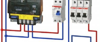
Socket connection system via difavtomat
The two-level system of RCD and difavtomat is optimal from the point of view of convenience. A general differential circuit breaker provides additional protection for the entire apartment not only from leakage current, but also from network overloads and short circuits. This scheme is recommended for use in residential premises with highly branched wiring.
It is advisable to install an additional RCD in the form of a socket in case of frequent power outages when a general apartment circuit breaker is triggered due to one household device
When the electrical mechanism of the socket is triggered, it will turn off without de-energizing the entire apartment, while the remaining rooms will remain under backup protection.
A difavtomat may have the same threshold current as a socket with an RCD, or maybe more (100 mA). If its value is the same, both devices connected in series can simultaneously knock out. The advantages of connecting the socket to ground remain the same as in the previous scheme without a difavtomat.
Single level multiple socket system
When several sockets with RCDs are connected to the network, the principle of their operation does not change. Each device ensures the safety of using household appliances connected to it.
Sockets with RCDs certainly increase the safety of using household appliances, but from a financial point of view such a scheme is impractical
This circuit is installed quite simply and does not require the installation of a general circuit breaker or RCD. The advantages of connecting grounding remain the same as in the previous options considered.
The differences in the operating principles of an RCD and a differential circuit breaker are given in the article, the contents of which we recommend that you familiarize yourself with.
The only disadvantage of a system of several outlets is their cost, because you will have to pay a considerable price for each device. An alternative to this option is to install one RCD for the entire room.
Not recommended circuit without grounding
The schematic diagram for connecting sockets with an RCD in the absence of grounding is almost no different from the two-level and single-level options proposed above. The only difference is the absence of a wire, which ensures that current is drawn from the body of the household appliance if its electrical insulation is damaged.
The connection diagram for a socket with an RCD without grounding can be used both in the presence of a common circuit breaker and in its absence
In fact, the vast majority of houses and high-rise buildings were not equipped with grounding until 2000, so this connection scheme is the most common. However, there is a hidden danger in it - the lack of contact between the body of the household appliance and the “ground”.
This fact is not only a problem for human health, but also has a negative impact on the performance of microcircuits in household appliances. Therefore, the presence of a ground bus in home electrical wiring is extremely necessary and desirable.
Basic principles of connection
To connect the RCD in the panel, two conductors are needed. Through the first of them, the current flows to the load, and through the second, it leaves the consumer along the external circuit.
As soon as current leakage occurs, a difference appears between its values at the input and output. When the result exceeds a predetermined value, the RCD is triggered in emergency mode, thereby protecting the entire apartment line.
Residual current devices are negatively affected by short circuits (short circuits) and voltage surges, so they themselves need to be covered. The problem is solved by including automata in the circuit.
The RCD contains a ring-shaped core with two windings. The windings are identical in their electrical and physical characteristics
The current powering electrical appliances flows through one of the core windings in one direction. It has a different direction in the second winding after passing through them.
Independent installation of protection devices involves the use of diagrams. Both modular RCDs and machines for them are installed in the panel.
Before starting installation, you need to resolve the following issues:
- how many RCDs should be installed;
- where they should be in the diagram;
- how to connect so that the RCD works correctly.
The rule of electrical installation is that all connections in a single-phase network must enter the connected devices from top to bottom.
Professional electricians explain this by saying that if you start them from below, the efficiency of the vast majority of machines will decrease by a quarter. In addition, the foreman working in the switchboard will not have to further understand the circuit.
RCDs designed for installation on separate lines and with low ratings cannot be installed in a general network. Failure to comply with this rule will increase both the likelihood of leaks and short circuits.
Characteristics of sockets with RCD
Modern sockets with RCDs are not installed in every apartment. The reason for this is the predominant installation of these devices or automatic devices at the common entrance of wires into the living space.
To decide on the best option for arranging electrical protection at home, you need to familiarize yourself in detail with the pros and cons of sockets with RCDs.
Advantages of combined devices
2-in-1 current leakage protection devices are not often used, but they have a number of advantages that make them indispensable in a number of cases.
The threshold differential current is always indicated on the front panel of the socket, therefore it is a key characteristic that determines its electrical safety function
The advantages of sockets with RCD include such qualities as:
- guaranteed blocking of electric shock in the presence of its leakage;
- no need for additional wiring or purchase of an expensive general high-power difavtomat;
- versatility in networks with different voltages;
- the ability to plug in any household appliance with a power of up to 3 kW;
- performance monitoring using a special testing button;
- possibility of operation at leakage currents of 10 mA;
- protection in case of damage to the neutral wire;
- ease of installation;
- compactness;
- presence of a voltage indicator in a visible place.
The listed advantages of sockets with RCDs make them indispensable if you want to quickly provide additional protection against leakage current. In addition, these devices are quite mobile and can always be moved to another location within a few minutes.
Disadvantages of combining a socket and an RCD
There are not many sockets with RCDs and similar portable devices for sale. The reason for this is a number of their shortcomings, which force consumers to choose other devices.
With the same functionality, the cost of sockets with RCDs from different brands can differ tens of times, although the reliability of these devices is approximately the same
The disadvantages of protective sockets include:
- High cost. It is much easier to install one RCD for an entire apartment or a group of rooms than to install a separate device in each socket.
- Availability of competitive devices in the form of automatic devices, which also provide additional protection in the event of network overload or wire short circuit.
- Frequent false alarms, especially in old houses with damaged wire insulation.
- Many models require deep socket boxes, which complicates their installation.
Thus, sockets with RCDs are a rather highly specialized product. It is used only when there is no desire or opportunity to install common circuit breakers in an apartment, or there is a need for protection with a threshold level of 10 mA.
How to calculate RCD
In order to calculate the protective device and solve the problem of how to choose an RCD based on power, the table of parameters will help you do this as quickly and accurately as possible. It is necessary to use two technical characteristics - leakage current and maximum current - to obtain the desired result. The calculations use a mains voltage of 220 V, with a frequency of 50 Hz.
Calculation and selection of the maximum current rating of the RCD is quite simple. It is necessary to establish the value of the total electrical power of devices and equipment turned on simultaneously. For example, if this indicator is 6000 watts, then the calculated current value will be equal to: I = P/U. Substituting the required values into the formula, we get the result: 6000W/220V = 27A. The closest RCD from the standard range of rated currents will be 32A.
If the RCD is calculated based on leakage current, in this case a simplified scheme is used, according to which various types of protective devices are selected in accordance with the operating conditions of the objects:
- In ordinary residential premises - at 30 mA.
- In bathrooms, kitchens and other rooms with high humidity and higher requirements for electrical safety - 10 mA.
- At large facilities with electrical networks over 1000 m in length or at the input - 100 mA.
Quite often there is a need to select an RCD for a group of machines, the calculation of which is carried out according to certain rules. The installation of these devices in the circuit is carried out sequentially; the machines can be installed both before and after the RCD. The current values of the circuit breakers must be lower than in the RCD, but not less than the actual current consumption. Correct calculation of RCDs and circuit breakers shows that in the event of overloads and short circuits, the circuit breaker will protect not only the line itself, but also the residual current device installed on it.
Rules for connecting to the network
Connecting a built-in socket with an RCD to the network is quite simple.
The maximum list of actions for this may look like this:
- Select a socket box of the appropriate size for the device.
- Drill a hole in the wall with a crown and connect phase, neutral and grounding (if available) to it.
- Turn off the power.
- Connect the electrical wires to the appropriate terminals on the outlet.
- Secure the device in the socket.
- Turn on the electricity.
- Click the “Test” button and check the functionality of the device. Normally, the power supply should be turned off immediately.
Installation of the device in the form of a monoblock adapter is not required at all. It is inserted into a simple socket, and on the other side household appliances are connected to it.
Image gallery
Photo from
Stage #1 - Drilling a hole for the socket
Stage #2 - Stripping Electrical Wires
Stage #3 - Screwing the socket to the wall
Stage #4 - Testing the RCD operation
To install a socket with an RCD on a DIN strip, you simply need to secure it, connect the corresponding wires to the terminals and test. After this, the device is ready for use.
Installation of RCDs and automatic machines in the panel
The electrical panel, in which the metering and load distribution devices are located, is usually the place for installing the RCD. Regardless of the chosen scheme, there are rules that are mandatory when connecting.
Main rules of connection
Along with the automatic shutdown device, automatic switches are also installed on the panel. All you need for this is a minimum of tools and a competent diagram.
The standard set should consist of:
- from a package of screwdrivers;
- pliers;
- side cutters;
- tester;
- socket wrenches;
- Cambric.
Also for installation you will need a VVG cable of different colors, selected in cross-section in accordance with the currents. The PVC insulating tube is used to mark the conductors.
When there is space on the DIN block available on the panel, a residual current device is mounted on it. Otherwise, install an additional one.
The key principle of installation is the following: contact of the neutral conductor after the RCD with either the input zero or grounding is unacceptable, therefore it is insulated in the same way as other conductors.
The circuit breaker must be switched on in series with the RCD. This is also one of the most important rules.
When the entire home is protected using one RCD, a circuit that includes several circuit breakers is used.
To eliminate the presence of additional wires on the shield, which does not look very aesthetically pleasing, a comb (distribution) bus is used to connect a bundle of wires
The project includes, in addition to additional AVs, one more component - a zero bus insulator. Mount it on the panel body or on a DIN rail.
This addition is introduced due to the fact that with a large number of neutral conductors connected to the output terminal of the disconnecting device, they simply will not fit in one clamp. An isolated zero bus is the best way out of this situation.
Sometimes electricians, in order to place the entire bundle of neutral wires in the socket, decide to cut the cores of a single-core cable. In the case where the cable is multi-core, several cores are removed.
It is better not to use this option, since due to a decrease in the cross-section of the conductors, the resistance will increase, and therefore the heating will increase.
Both the number of mounting holes and their diameter may vary. The ground bus is attached directly to the body.
Neutral wires in one twist are an additional inconvenience when identifying damage on the line, as well as when you need to dismantle one of the cables. Here you cannot do without unscrewing the clamp and unwinding the harness, which will certainly provoke the appearance of cracks in the veins.
You cannot install two wires simultaneously into one socket. The inputs of the circuit breakers are connected by jumpers. As the latter, during professional installation, special connecting tires called “comb” are used.
Features of connection diagrams
The choice of scheme involves taking into account the characteristics of a particular electrical network. Among the numerous options, there are only two circuits used to connect automatic machines and RCDs in the panel, which are considered the main ones.
The simplest installation diagram for automatic machines and protective devices. It can be used to connect from one to several loads connected in parallel
The first and simplest method, when one RCD protects the entire electrical network, has disadvantages. The main one is the difficulty in identifying the specific location of the damage.
The second is that when some kind of failure occurs in the functioning of the RCD, the entire system will be taken out of operation. The residual current device is allocated a place immediately after the meter.
The next method provides for the presence of such devices on each individual line. If one of them fails, all the others will be in working order. To implement this scheme, a larger shield and greater financial costs are required.
Details about a simple scheme
Let's consider connecting an RCD with automatic circuit breakers to a simple residential switchboard. At the entrance there is a two-pole automatic switch. A two-pole RCD is connected to it, to which there are two single-pole circuit breakers.
A load is connected to the output of each of them. In principle, an RCD is introduced into the circuit in the same way as a circuit breaker.
There is a “Test” button on the RCD body. It is intended to test its operation. Manufacturers advise using this key at least once a month and checking the operation of the device itself.
The phase supplied to the circuit breaker enters the input of the RCD with output to the circuit breakers. The zero output from the machine goes to the zero bus, and from it to the input to the device.
From its output, the neutral conductor is directed to the second neutral bus. The presence of this second bus contains a special nuance, without knowing about which it is impossible to achieve normal functioning of the circuit.
During operation, the RCD controls both incoming and output voltage - as much as is at the input, so much should be at the output.
If the balance is disturbed and the output is greater by the value of the setting to which the RCD is configured, it is triggered and the power is automatically turned off. The zero bus is responsible for this process.
In electrical circuits where the installation of a residual current device is not provided, there is only one common zero.
In circuits with RCDs the picture is different - there are already several such zeros present. When using one device, there are two of them - the common one and the one in relation to which the protective device operates.
If two RCDs are connected, there are three zero buses. They are designated by indices: N1, N2, N3, etc. In general, there are always one more zeros than residual current devices. One of them is the main one, and all the others are tied directly to the RCD.
Color designation of electrical wires according to the rules established by the PUE. This marking must be studied before proceeding with the installation of protective devices.
If not all equipment is supposed to be connected through the RCD, then zero is supplied from the common bus. In this case, the residual current device is removed from the circuit.
When adding a single-pole circuit breaker operating from an RCD, the phase from the output of the latter is supplied to the input of the circuit breaker. From the output of the switch, the conductor is connected to one load contact. Zero on it is brought to the second conclusion. It comes from the zero bus created by the RCD.
There is one more element on the shield - a protective grounding bus. Correct operation of the RCD without it is impossible.
Three-wire network is only available in new houses. It must have a zero phase and grounding. In houses built a long time ago, there is only a phase and a zero. In such conditions, the RCD will also function, but slightly differently than in a three-phase network.
As a way out, the grounding is carried out by a third conductor to the sockets, and then to the ceiling to the place where the chandeliers are connected. Ground is not supplied to the switches.
Option for connecting machines without RCD
There are times when one of the machines needs to be connected without bypassing the residual current device. Power is connected not from the output of the RCD, but from the input to it, i.e. directly from the machine. The phase is supplied to the input, and from the output it is connected to the left terminal of the load.
Zero is taken from the common zero bus (N). If a fault occurs in the area controlled by the RCD, it will be removed from the circuit, and the second load will not be de-energized.
RCD in a three-phase network
A network of this type includes either a special three-phase RCD with eight contacts, or three single-phase ones.
Place the RCD connection diagram on its body. Wires coming from the output terminals lead to the apartment's distribution network
The connection principle is completely identical. Mount it according to the diagram. Phases A, B and C supply power to loads rated at 380 V. If we consider each phase separately, then in tandem with cable N (0), it provides a series of single-phase 220 V consumers.
Manufacturers produce three-phase trip protection devices adapted to high leakage currents. They only protect electrical wiring from fire.
The photo shows two diagrams: a trip protection device in a single-phase and three-phase network of the TN-CS system. This means that the neutral cable is divided into working and protective
In order to protect people from the effects of electric current, single-phase two-pole RCDs are installed on the outgoing branches, configured for leakage current in the range of 10-30 mA. For cover, a machine gun is placed in front of everyone. In the circuit after the RCD, the working zero and ground cannot be connected.
Tips for choosing the right model
Choosing a suitable socket with an RCD is not difficult, because manufacturers offer mostly standard solutions, and the model range of these devices is small.
Leakage currents that can lead to fire are much higher than those that can kill a person. Therefore, household sockets with RCDs provide complete fire safety in case of insulation breakdown
When purchasing, you should pay special attention to the following nuances:
- For bathrooms, the degree of protection must be at least IP44, and for dry rooms - IP21 or IP22.
- For modern household appliances, you can take devices with a differential shutdown current level of 10 mA, and when connecting older devices - 30 mA.
- If you plan to connect long wires or several household appliances to the outlet, it is recommended to use models with a leakage current of at least 30 mA.
- The maximum power of the connected equipment should not be higher than that indicated on the outlet. It is recommended that the permissible current be 30-50% higher than the actual operating current.
- The statistics of defects and false positives are almost the same for most well-known brands, so it’s not worth overpaying for the name.
- Each device, unlike simple sockets, must have a technical passport or operating instructions indicating technical parameters.
If you purchase a socket adapter, you can check its functionality right in the store. It is enough to turn on its power supply and press the “Test” button, which simulates a current leak.
After purchase, you need to keep the receipt so that if a defect is detected, you can exchange the device.
Download
For those who want to delve deeper into the topic, I am posting GOST, according to which RCDs (differential switches) are produced and selected. And a reference book on RCDs.
• GOST R 51326.1-99 / GOST R 51326.1-99 (IEC 61008-1-96) Automatic switches, controlled by differential current, for household and similar purposes without built-in overcurrent protection. Part 1. General requirements and test methods, pdf, 1.64 MB, downloaded: 1178 times./
• GOST R 50571.3-2009 (IEC 60364-4-41:2005) / GOST R 50571.3-2009 (IEC 60364-4-41:2005) Low-voltage electrical installations. Part 4-41. Security requirements. Protection against electric shock, pdf, 263 kB, downloaded: 1086 times./
• Dushkin N.D. and other RCD, educational and reference manual. / RCD - residual current devices, educational and reference manual., pdf, 8.44 MB, downloaded: 1610 times./
Let me remind you that the second part about the design of RCDs and automatic devices is here.
As always, I'd love to discuss!