Electrical installation rules indicate that for portable lighting the voltage should not be more than fifty volts, and if the space is enclosed, no more than twelve volts.
In this case, electricity is supplied through a transformer, thanks to which a person may not be afraid of electric shock. At the same time, electricity may be unsafe even for connecting small-sized equipment.
In this article we will look at options with which you can change the voltage to the required values.
What is the voltage drop across a resistor
Electric current passing through a circuit experiences resistance, which can change under the influence of various environmental conditions (extremely low temperatures or heat) and may depend on the characteristics of the particular conductor.
For example, the thinner the conductor or longer, the higher it is. The value of its value is influenced by the following factors:
- current strength;
- length of conductive parts;
- voltage;
- conductor element material;
- heating (temperature);
- cross-sectional area.
Resistors can be divided into constant, variable and trimming. Their main difference from each other is the ability to change the resistance indicator. The most common ones are fixed resistors - this indicator cannot be changed in them, which is why they got that name. Variables differ in that the resistance value in them can be adjusted. In a trimmer resistor it can also be changed, but the difference between this type is that it is not designed for frequent changes of the parameter. Trimmer resistors are made in a more compact package compared to variables.
To calculate the voltage drop across a resistor, you need to remember that the reduction in load applied to the entire circuit (that is, the voltage connected to the circuit) can be obtained both for the entire circuit and for any element in the circuit. The voltage is reduced due to the resistance that the conductors have.
The voltage drop across the resistor depends on the strength of the current passing and the characteristics of the conductors. Temperature and current readings also matter. For example, the voltage measured by a voltmeter on a light bulb connected to a 220 V network will be slightly lower due to the resistance that the light bulb has.
Power supplies have different voltage levels. This value may exceed what is needed at the output. To prevent the load that needs to be powered from burning out, it is often necessary to lower the voltage, including using resistors.
Voltage comparison table
| Power supply | Voltage |
| NiCd battery | 1.2 V |
| Lithium iron phosphate battery | 3.3 V |
| Battery type "Krona" | 9 V |
| Car battery | 12 V |
| Truck battery | 24 V |
In this case, the resistor should reduce the current flowing through the circuit. In this case, the current does not turn into heat, it is precisely its limitation that occurs. That is, when a resistor is connected to the circuit, the current will drop - this is the work of the resistor, during which the element heats up.
In general, voltage drops can be calculated using a simple formula that relates the indicators to each other.
But in some cases, for example, when connecting resistances in parallel, it is more difficult to calculate the required value. In this case, using a special formula, you will need to bring the resistance of parallel branches to one number:
R = R1*R2 / (R1+R2)
If necessary, other resistances that add up to this value are also taken into account (for example, resistance of the wire and power supply).
Divider on capacitors
A very popular circuit used to reduce the value of the AC supply network. It cannot be used in DC circuits, since, according to Kirchhoff’s theorem, a capacitor in a DC circuit is a break. In other words, no current will flow through it. But when operating in an alternating current circuit, the capacitor has reactance, which is capable of extinguishing the voltage. The divider circuit is similar to the one described above, but capacitors are used instead of inductors. The calculation is made using the following formulas:
- Capacitor reactance: X(C) = 1 / (2 * 3.14 *f * C).
- Voltage drop across C1: U(C1) = (C2 * U) / (C1 + C2).
- Voltage drop across C2: U(C1) = (C1 * U) / (C1 + C2).
Here C1 and C2 are the capacitances of the capacitors, U is the voltage in the supply network, f is the current frequency.
Physical definition
A resistor is an element used in an electrical circuit and does not require a power source for its operation. It is designed to transform current into voltage and vice versa. In addition, it can convert electrical energy into thermal energy and limit the amount of current. But before calculating the voltage drop across a resistor, it is advisable to understand the essence of this process.
A resistor is a very common element characterized by a number of parameters. The main ones are:
- resistance;
- the amount of energy dissipated;
- operating voltage;
- power;
- resistance to environmental influences;
- parasitic component.
A passive electrical element is indicated in the diagram as a rectangle with two terminals from the middle of its sides. In the center of the figure, power can be indicated in Roman numerals or dashes. For example, a vertical stripe indicates the element's withstand power of 1 W. The crossed out rectangle in the notation in the diagram indicates that such a resistor is variable.
Resistors can be produced with constant and variable resistance. A type of the latter are tuning elements. The only difference between them and variables is the way they are set to the desired value.
On diagrams and in technical literature, the device is designated by the Latin letter R, next to which the serial number and its denomination are indicated in accordance with the International System of Units (SI). For example, R12 5 kOhm is a five kilo-ohm resistor located in the circuit under number 12.
When manufacturing an element, a resistive layer is used, which can be film or volumetric. It is applied to a dielectric base and covered with a protective film on top.
Resistance value
Resistance is a fundamental quantity in electrical processes. Its meaning is invariably related to current and voltage. Their general dependence is described using Ohm's law: the current strength arising in a section of the circuit is directly proportional to the potential difference between the extreme points of this section and inversely proportional to its resistance. From this law the resistance is found using the following formula:
R = U / I, where:
- R is the resistance in the circuit section, Ohm.
- I is the current strength passing through this section, A.
- U is the potential difference at the nodes of a part of the circuit, V.
In fact, the resistance of an element is determined by its physical structure and is caused by the vibrations of atoms in the crystal lattice. Therefore, all materials are classified as conductors, semiconductors and dielectrics depending on their ability to conduct electricity.
Current is the directed movement of charge carriers. For it to occur, the substance must have free electrons. If an electric field is applied to such a physical body, then the charges it moves will begin to collide with inhomogeneities in the structure. These defects are formed due to various impurities, violation of lattice periodicity, and thermal fluctuations. By hitting them, the electron expends energy, which is converted into heat. As a result, the charge loses momentum, and the magnitude of the potential difference decreases.
But Ohm's law cannot be applied to all substances. In electrolytes, dielectrics and semiconductors, a linear relationship between the three quantities is not always observed. The resistance of such substances depends on the physical parameters of the conductor, namely its length and cross-sectional area, and it is sensitive to temperature changes.
This dependence is described using the formula R = p * l / S. That is, the resistance is directly proportional to the length and inversely proportional to the area of the conductor. The value p is called resistivity and is determined by the type of material. Its meaning is taken from the reference book.
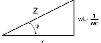
Resistor impedance
Ohm's law applies to an ideal resistor that has no parasitic resistance. The total resistance (impedance) is determined based on the equivalent circuit. Accurate calculation of resistance to reduce voltage must be carried out using other formulas. The equivalent circuit of a resistor, in addition to active impedance, also contains capacitive and inductive reactance.
The first leads to a slow accumulation of charge, which dissipates when the direction of the current changes. The larger the parasitic capacitance, the longer it takes to charge. Accordingly, the faster the current changes its direction, the lower its capacitance. The second is characterized by a magnetic field, whose appearance prevents the current from changing direction, therefore, the faster the current changes its movement, the greater the inductive reactance becomes.
Impedance is calculated using the formula: I = U/Z, where Z = (R2+(Xc-Xl)2)½. Where:
- R is the active value, R = p*l/s.
- Xc is a capacitive value, Xc = 1/w*C.
- Xl is an inductive quantity, Xl = w*C.
- w is the cyclic frequency, w = 2πƒ.
Knowing the total resistance of the resistor, you can more accurately calculate the voltage drop in it. But to measure parasitic components you will need to use highly specialized instruments. In conventional calculations, resistance is calculated taking into account only its active value, and parasitic values are taken as negligible.
How do you increase and decrease voltage?
Increasing and decreasing voltage is carried out using transformers
.
The transformer consists of two coils of insulated wire wound on a common steel core (Fig. 16.4).
One coil (called the primary winding) is supplied with alternating current of one voltage, and the other coil (called the secondary winding) is supplied with alternating current of a different voltage.
Rice. 16.4. Step-up and step-down transformers.
It is concentrated mainly inside the steel core, so both windings are threaded with the same
variable magnetic flux.
Therefore, due to the phenomenon of electromagnetic induction in each turn of each winding
the same induced emf occurs.
The total emf in each of the coils is equal to the sum of the emf in all its turns, since the turns are connected to each other in series. Therefore, the ratio of voltages in the secondary and primary windings is equal to the ratio of the number of turns in them: For example, if the secondary winding has 10 times more turns than the primary, the voltage in the secondary winding will be 10 times greater than in the primary.
If the voltage in the secondary winding of the transformer is greater than in the primary, it is called step-up
, and if less, then
downward
.
The main consumers of electricity are manufacturing and transport. Domestic needs account for no more than 5-10% of all electricity produced.
Rice. 16.5. The main stages of production, transmission and consumption of electricity.
Encyclopedia articles
Resistor power characteristic
The power of the electric current in a section of the circuit can be found through the product of the current strength for it and the voltage in this section. The formula is as follows: P= I * U (product of current and voltage), where
P – power value (W).
The resistor does work to reduce the current, while it releases heat into the surrounding space. But if the work to limit the current is very great and heat is generated too quickly, then it will overheat and may burn out, since it will not have time to dissipate it. This point should be taken into account when selecting the resistor power
Important! The power of a resistor is a very important parameter that must be taken into account when developing electrical circuits for devices. The power of a resistor is characterized by the maximum amount of current that it can withstand without overheating or failing.
Using a ballast capacitor for low power devices
It is not necessary to use a transformer to step down the voltage in every case. A ballast capacitor can also help in such situations. These devices operate by limiting the current using capacitance resistance.
It is necessary to correctly calculate the capacity taking into account the power of current consumption in the network.
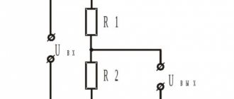
Voltage divider circuit using resistors
The voltage divider circuit includes an input voltage source and two resistors. Below you can see several schematic versions of the divider, but they all have the same functionality.
We recommend reading: DIY DC voltage multiplier
Let's denote the resistor that is closer to the plus of the input voltage (Uin) as R1, and the resistor that is closer to the minus as R2. The voltage drop (Uout) across resistor R2 is the reduced voltage resulting from the use of a resistor voltage divider.
Voltage regulation at the transformer output
In the supply line from the TM 35/6.3 transformer to the TM 6/0.4 transformer and in the TM 35/6.3 transformer itself, the voltage loss is 5% (300 V) and the primary winding of the TM 6/0.4 transformer will receive voltage 6000 V (Fig. 2.67).
Rice. 2.67. Power supply diagram for transformer TM 6/0.4 and power receiver
If the TM 35/6.3 substation is located close to the 6/0.4 substation, then the voltage losses in the supply line will be minimal and the primary winding of the TM 6/0.4 transformer will receive a voltage greater than the rated one, equal to 6000 V, for example, 6300 IN.
The voltage on the secondary winding of the TM 6/0.4 transformer will be 5% more than 400 V, i.e. 420 V. At the terminals of the electrical receiver, the voltage will be greater than the nominal, equal to 380 V, and will be 400 V. Overvoltage at the terminals of the electrical receiver, for example, incandescent lamps, leads to rapid failure (burn out).
The main tap corresponds to a rated voltage of 6000 V and a rated transformation ratio (Fig. 2.68).
Rice. 2.68. Branches from the primary winding of the transformer
is in the middle position on the main tap and the voltage = 400 V at idle.
where is the number of turns of the primary winding; – number of turns of the secondary winding.
If =6.300 V, then it is necessary to increase the K
From the ratio it is necessary to increase the number of turns. Switch P
If =5700 V, then it is necessary to reduce the coefficient K
, i.e. reduce the number of turns. Switch P
is set to the -5% position and the secondary voltage equal to 400 V.
Tap switching is carried out only after the transformer is disconnected from the network and is called “tap switching of windings without excitation (PWB)”.
More advanced is on-load regulation (OLTC), which is carried out without breaking the circuit. The switch is placed in the common transformer tank above the magnetic circuit and is driven by an electric motor. The on-load tap-changer kit includes a switching device and an automatic drive control unit.
In table Figure 2.18 presents power data for power transformers.
Scale of rated power of power transformers
Rice. 2.69. Scheme for including protections in YAKNO:
How to calculate resistance for voltage drop: resistor drop formula
A resistor is one of the most common elements in an electrical circuit. With its help, the current is limited and the voltage is changed. When designing circuits, you may often need to calculate the resistance to reduce the voltage. This is relevant when constructing dividers for digital devices or power supplies, so every radio amateur should be able to perform such calculations.
A resistor is an element used in an electrical circuit and does not require a power source for its operation. It is designed to transform current into voltage and vice versa. In addition, it can convert electrical energy into thermal energy and limit the amount of current. But before calculating the voltage drop across a resistor, it is advisable to understand the essence of this process.
A resistor is a very common element characterized by a number of parameters. The main ones are:
- resistance;
- the amount of energy dissipated;
- operating voltage;
- power;
- resistance to environmental influences;
- parasitic component.
A passive electrical element is indicated in the diagram as a rectangle with two terminals from the middle of its sides. In the center of the figure, power can be indicated in Roman numerals or dashes. For example, a vertical stripe indicates the element's withstand power of 1 W. The crossed out rectangle in the notation in the diagram indicates that such a resistor is variable.
Resistors can be produced with constant and variable resistance. A type of the latter are tuning elements. The only difference between them and variables is the way they are set to the desired value.
On diagrams and in technical literature, the device is designated by the Latin letter R, next to which the serial number and its denomination are indicated in accordance with the International System of Units (SI). For example, R12 5 kOhm is a five kilo-ohm resistor located in the circuit under number 12.
When manufacturing an element, a resistive layer is used, which can be film or volumetric. It is applied to a dielectric base and covered with a protective film on top.
Resistance value
Resistance is a fundamental quantity in electrical processes. Its meaning is invariably related to current and voltage. Their general dependence is described using Ohm's law: the current strength arising in a section of the circuit is directly proportional to the potential difference between the extreme points of this section and inversely proportional to its resistance. From this law the resistance is found using the following formula:
R = U / I, where:
- R is the resistance in the circuit section, Ohm.
- I is the current strength passing through this section, A.
- U is the potential difference at the nodes of a part of the circuit, V.
In fact, the resistance of an element is determined by its physical structure and is caused by the vibrations of atoms in the crystal lattice. Therefore, all materials are classified as conductors, semiconductors and dielectrics depending on their ability to conduct electricity.
Current is the directed movement of charge carriers. For it to occur, the substance must have free electrons. If an electric field is applied to such a physical body, then the charges it moves will begin to collide with inhomogeneities in the structure. These defects are formed due to various impurities, violation of lattice periodicity, and thermal fluctuations. By hitting them, the electron expends energy, which is converted into heat. As a result, the charge loses momentum, and the magnitude of the potential difference decreases.
But Ohm's law cannot be applied to all substances. In electrolytes, dielectrics and semiconductors, a linear relationship between the three quantities is not always observed. The resistance of such substances depends on the physical parameters of the conductor, namely its length and cross-sectional area, and it is sensitive to temperature changes.
This dependence is described using the formula R = p * l / S. That is, the resistance is directly proportional to the length and inversely proportional to the area of the conductor. The value p is called resistivity and is determined by the type of material. Its meaning is taken from the reference book.
Resistor impedance
Ohm's law applies to an ideal resistor that has no parasitic resistance. The total resistance (impedance) is determined based on the equivalent circuit. Accurate calculation of resistance to reduce voltage must be carried out using other formulas. The equivalent circuit of a resistor, in addition to active impedance, also contains capacitive and inductive reactance.
The first leads to a slow accumulation of charge, which dissipates when the direction of the current changes. The larger the parasitic capacitance, the longer it takes to charge. Accordingly, the faster the current changes its direction, the lower its capacitance. The second is characterized by a magnetic field, whose appearance prevents the current from changing direction, therefore, the faster the current changes its movement, the greater the inductive reactance becomes.
Impedance is calculated using the formula: I = U/Z, where Z = (R2+(Xc-Xl)2)½. Where:
- R is the active value, R = p*l/s.
- Xc is a capacitive value, Xc = 1/w*C.
- Xl is an inductive quantity, Xl = w*C.
- w is the cyclic frequency, w = 2πƒ.
Knowing the total resistance of the resistor, you can more accurately calculate the voltage drop in it. But to measure parasitic components you will need to use highly specialized instruments. In conventional calculations, resistance is calculated taking into account only its active value, and parasitic values are taken as negligible.
Parallel connection
Electrical circuits use both parallel and series connections in sections of the circuit. The first is a circuit in which each element is connected to the other by both contacts, but there is no direct electrical connection between its own terminals. That is, there are two points (electrical nodes) to which several resistors are connected.
With this switching on, the current passing through the node begins to split, and a different value will flow through each element. The amount of current in each element will be directly proportional to the resistance of the resistor, so the total conductivity in this section will increase, and its impedance will decrease.
The formula with which you can calculate the total conductivity looks like this: G = 1/ Rtot = 1/ R1 + 1/ R2 +…+ 1/ Rn, where n denotes the serial number of the resistor in the circuit.
Transforming this formula, you get an expression of the form: R total = 1/G = (R1*R2*…* Rn) / (R1*R2 + R2*Rn +…+ R1*Rn. Having analyzed it, we can conclude that with parallel connection, the impedance will always be less than the smallest value of an individual resistor.
With such a connection, the voltage between the nodes is simultaneously the total potential difference for the entire section and at each individual resistor. Therefore, if you calculate the voltage drop on one device, then it will be the same on any parallel-connected element: U total = U 1 = U 2 =...= U n.
But the electric current passing through a separate element, based on Ohm’s law, will be equal to: I Rn = U Rn / R n.
Serial connection
This is the name for combining two or more resistors into one section of a circuit, in which their connection to each other occurs only at one point. Impedance when connected in series is defined as the sum of the resistances of each individual element: Rtotal = R1+R2+…+Rn.
Consequently, the current flowing through such a chain will become less and less after passing through a series-connected resistor. The more elements there are in the chain, the more difficult it will be for him to pass them all. Thus, its overall value is determined as Itotal = U / (R1+R2+…+Rn).
Therefore, it can be argued that in a series connection there is only one path for current to flow. The greater the number of resistors in the line, the less current will be in this section.
We recommend reading: How to check a battery with a multimeter: for performance
The drop in potential difference with this type of connection on each element will have its own meaning. It is determined by the formula URn = IRn*Rn, and the greater the impedance of the element, the more energy it will begin to release.
Voltage divider calculation
A resistive voltage divider represents a basic circuit for reducing voltage. It can consist of two or more elements. The simplest divider can be represented as two sections of the chain, which are called shoulders. One of them, which is located between the positive and zero potential points, is the upper one, and the other, between the negative and minus ones, is the lower one.
This circuit is used to reduce voltage in both constant and variable circuits. The essence of the process is as follows.
- The resistive circuit is supplied with voltage U from the power source.
- Current begins to flow through the resistors of the series section of the circuit formed by resistors R1 and R2.
- As a result, a certain amount of energy is released at each of them, i.e., a voltage drop occurs.
The sum of the voltages across the entire line span is equal to the potential difference of the power source. In accordance with the formula: U = I*R, the voltage drop is directly proportional to the current strength and resistance value. Considering that the current flowing through the resistors is the same, the formulas U1 = I*R1 and U2= I*R2 will be valid.
Then the total voltage drop in the section will be equal to U = I * (R1+ R2). Based on this, you can find the current strength: I = U / (R1+ R2). Using these two expressions, the final formulas for calculating the voltage drop across each element can be obtained:
- U1 = R1*U/(R1+R2);
- U2 = R2*U/(R1+R2).
The practical use of such a divider is very common due to the ease of implementing voltage reduction. For example, let the power supply supply 12 V, and the load needs to be supplied with 6 V, while its resistance is 10 kOhm. To solve this problem, it is recommended to use resistors whose resistance is ten times less than the load value, therefore, taking R 1 = 1 kOhm and substituting all known values into the voltage formula on the resistor, it turns out that 6 = R 2 * 12 (1000+ R 2 ) hence R 2 = 1 kOhm.
Now, knowing all the values, you can check the accuracy of the calculation. The potential difference drop across the first element is calculated as U 1 = 1000*12/(1000+1000) = 6 V, and the total voltage is Utot = U 1+ U 2 = 12 V, which corresponds to the value of the power source.
It should be noted that the use of pull-down resistors is only used for low-power loads, since some of the energy is converted into heat and the coefficient of performance (COP) is very low.
How to reduce transformer voltage
How to reduce the voltage on a transformer.
Hello colleagues!
In this article I will tell you how to make a transformer with a 12 V output from a transformer with a 32 V output. In other words, reduce the voltage of the transformer.
For example, I’ll take the trance from the Chinese b/w TV “Jinlipu”.
I think a lot of people have met him or similar.
So, first we need to define the primary and secondary windings. To do this, you need a regular ohmmeter. We measure the resistance at the terminals of the transformer.
On the primary winding, the resistance is greater than on the secondary and is usually at least 85 ohms. Once we have identified these windings, we can begin to disassemble the transformer. It is necessary to separate the W-shaped plates from each other.
To do this, we will need some tools, namely: round nose pliers, pliers, a small screwdriver for “picking up” the plates, wire cutters, and a knife.
To pull out the very first record, you will have to work hard, but then the rest will go like clockwork.
You need to work very carefully, as you can easily cut yourself on the plates
On this particular transformer, we know that it has 32 V output.
In the case when we do not know this, we must measure the voltage before analysis, so that in the future we can calculate how many turns go to 1 V.
After the plates have been removed, you need to remove the plastic case from the windings. We do this boldly, since this will not affect the operation of the transformer in any way.
Then we find a contact on the secondary winding that is accessible for unwinding and use wire cutters to “bite it off” from the soldering point. Next, we begin to unwind the winding, and be sure to count the number of turns. To keep the wire out of the way, you can wrap it around a ruler or something similar.
Since this transformer has 3 terminals on the secondary winding (two extreme and one middle), it is logical to assume that the voltage at the middle terminal is 16V, exactly half of 32V. We unwind the winding to the middle contact, i.e. to half, and count the number of turns that we unwound.
(If the transformer has two terminals on the secondary winding, then unwind it “by eye” to half, count the turns while doing so, then cut off the unwound wire, strip its end, solder it back to the contact and assemble the transformer, doing everything the same as when disassembling, just in reverse order.
The number of turns you unwound is 105. This means 105 turns per 17V (35V-18V=17V). It follows that there are approximately 6.1 turns per 1B (105/17 = 6.176). Now, in order for us to reduce the voltage by another 6V (18V-12V=6V), you need to unwind approximately 36.6 turns (6.1*6=36.6). You can round this figure to 37.
To do this, you need to disassemble the transformer again and do this “procedure.”). In our case, having reached half of the winding, we got 106 turns. This means that these 106 turns are at 16V. We calculate how many turns there are per 1V (106/16=6.625) and unwind about 26.5 more turns (16V-12V=4V; 4V*6.625 turns=26.5 turns).
Then we “bite off” the unwound wire, strip the varnish from its end, tin it and solder it to the contact on the transformer from which it was “bitten off”.
It remains to measure the voltage that we got:
Congratulations, colleagues, everything turned out great!
In the next article I will tell you how to make a 12V DC power supply from this transformer.
Determining the current strength across a resistor for different types of connection
The easiest way to determine the current in a resistor is to use a multimeter. The measurement is carried out in the open circuit after the resistor. The maximum range of values is set on the tester, and the probes of the device are connected to the place where the conductor is disconnected. The multimeter display will show the results of measuring the current in the resistor. I = U/R, where we have I – current, U – voltage, R – resistance.
In the SI system, these quantities are measured in amperes (A), volts (V), ohms (Ohm), respectively.
By substituting the required values into the formula, you can determine the resistance, voltage and current on a resistor or any section or element of an electrical circuit.
Transformerless power supply: possible schematic solutions
Linear stabilizer chip
You can assemble a simple driver (stabilized current source) with your own hands using an inexpensive ($0.3) linear stabilizer chip LM317AMDT. The input of the DC-AC converter is supplied with a mains voltage of 220 V, 50 Hz.
A stabilized voltage of 12 V is obtained on the IC with a minimum set of elements in the harness (in the simplest version, only R1 and R2 are used). By selecting the value of the resistors, you can regulate the current in the load; with a total LED current of up to 0.3 A, the microcircuit works perfectly without a radiator. Below is a typical circuit diagram of a device based on the LM317 chip:
Charger
The most budget option, of course, is to use a charger from a cell phone. The charger board has very small dimensions and is suitable for powering a 12 V gadget with a power ≤ P rated. power supply. It is only necessary to replace the half-wave rectifier with a rectifier with double the voltage (add one diode and capacitor each). After modernization, we get the required 12 volts with a current of 0.5A and full isolation from the network.
As an alternative that does not require intervention in the design, a step-up DC-DC voltage converter (for example, 2-amp, 30mm x 17mm x 14mm, costing $1) with a USB connector can be connected to the output of the charger through an adapter. All you need to do is set the trimming resistor to the required voltage of 12 V and connect the converter to a gadget or stationary power receiving device.
How to lower voltage using a resistor
To prevent the load that needs to be powered from burning out, it is often necessary to reduce the input voltage. The easiest way to achieve this is to use a two-resistor circuit, better known as a voltage divider. The classic scheme looks like this:
In this case, the voltage is supplied to two resistors using a parallel connection, and at the output it is received from one. The selection of resistor values is carried out according to the formula so that the voltage removed at the output is some part of the supplied one. You can calculate a resistor to reduce the voltage using a formula based on Ohm's law:
Uout= (Uin*R2)/(R1+R2), where
Uin – input voltage, V;
Uout – output voltage, V
R1 – resistance index. 1st resistor (Ohm)
R2 – resistance index. 2nd element, (Ohm)
Selecting a resistor to reduce voltage
To select the required resistor resistance, you can use ready-made online calculators or programs for simulating the operation of electronic circuits. Electrical circuit simulators are capable of not only calculating the output voltage depending on the resistance of the elements and the method of their connection, but also have functionality that allows you to visualize how the current and voltage across the resistor drops. For example, the EveryCircuit application allows you to change the parameters of elements in the circuit, select the simulation speed, and obtain data at various points. In this case, you can observe the dynamics of changes in values using the rotating dial in the lower right corner to enter input parameters.
There are also a number of free emulation programs that allow you to perform, among other things, calculations of a resistor when the voltage drops, for example:
- EasyEDA;
- Circuit Sims;
- DcAcLab;
and others.
In the article, we became acquainted with the concept of resistance, learned about its units of measurement, the marking of resistors, programs that emulate the operation of a circuit and facilitate the selection of the desired resistance, and also looked at examples of calculating the voltage drop across a resistor.
Voltage stabilization
You have learned how to lower the voltage to the desired level. Now it needs to be stabilized. For this purpose, special devices are used - zener diodes, which are made of semiconductor components. They are installed at the output of the DC power supply. The principle of operation is that a semiconductor is capable of passing a certain voltage, the excess is converted into heat and released through a radiator into the atmosphere. In other words, if the output of the power supply is 15 volts, and a 12 V stabilizer is installed, then it will pass exactly as much as needed. And the difference of 3 V will be used to heat the element (the law of conservation of energy applies).
What is the voltage after the resistor
There is another way to reduce the voltage across the load, but only for DC circuits. See about it here.
Instead of an additional resistor, a chain of diodes connected in series in the forward direction is used.
The whole point is that when current flows through the diode, a “forward voltage” drops across it, equal to, depending on the type of diode, power and current flowing through it, from 0.5 to 1.2 Volts.
On a germanium diode the voltage drops 0.5 - 0.7 V, on a silicon diode from 0.6 to 1.2 Volts. Based on how many volts you need to reduce the voltage at the load, turn on the appropriate number of diodes.
To lower the voltage by 6 V, you need to approximately turn on: 6 V: 1.0 = 6 pieces of silicon diodes, 6 V: 0.6 = 10 pieces of germanium diodes. The most popular and accessible are silicon diodes.
The above circuit with diodes is more cumbersome to implement than with a simple resistor. But the output voltage in a circuit with diodes is more stable and weakly dependent on the load. What is the difference between these two methods of reducing the output voltage?
A resistor (wire resistance) has a linear relationship between the current passing through it and the voltage drop across it. By how many times the current increases, the voltage drop across the resistor will increase by the same amount.
From example 1: if we connect another one in parallel to a light bulb, the current in the circuit will increase, taking into account the total resistance of the two light bulbs to 0.66 A. The voltage drop across the additional resistor will be: 12 Ohm * 0.66 A = 7.92 V The light bulbs will remain: 12 V - 7.92 V = 4.08 V. They will burn at half incandescence.
A completely different picture will be if instead of a resistor there is a chain of diodes.
The relationship between the current flowing through the diode and the voltage dropped across it is nonlinear. The current can increase several times, the voltage drop across the diode will increase by only a few tenths of a volt.
Those. The greater the diode current, the less (compared to a resistor) its resistance increases. The voltage drop across the diodes depends little on the current in the circuit.
Diodes in such a circuit act as a voltage stabilizer. Diodes must be selected according to the maximum current in the circuit. The maximum permissible current of the diodes must be greater than the current in the circuit being calculated.
The voltage drops on some diodes at a current of 0.5 A are given in the table.
In AC circuits, a capacitor, inductance, dynistor or thyristor (with the addition of a control circuit) can be used as additional resistance.
For a person who is familiar with electrical equipment at the level of a simple user (knows where and how to turn it on/off), many of the terms used by electricians seem like some kind of nonsense. For example, what does “voltage drop” or “circuit assembly” cost? Where and what falls? Who took the circuit apart? In fact, the physical meaning of the processes occurring, hidden behind most of these words, is quite understandable even with school knowledge of physics.
We recommend reading: DIY time relay with delay: various assemblies and circuits
To explain what a voltage drop is, it is necessary to remember what kind of voltages there are in general (this refers to the global classification). There are only two types. The first is the voltage that is connected to the circuit in question. It may also be said to be applied to the entire circuit. And the second type is precisely the voltage drop. It can be considered both in relation to the entire contour and any individual element.
In practice it looks like this. For example, if you take a regular one, screw it into a socket, and connect the wires from it to a home power outlet, then the voltage applied to the circuit (power source - conductors - load) will be 220 Volts. But as soon as we measure its value on the lamp using a voltmeter, it will become obvious that it is slightly less than 220. This happened because there was a voltage drop across the lamp.
There is probably no person who has not heard of Ohm's law. In general, its formulation looks like this:
where R is the active resistance of the circuit or its element, measured in Ohms; U - electrical voltage, in Volts; and finally, I is the current in Amperes. As you can see, all three quantities are directly related to each other. Therefore, knowing any two, you can quite simply calculate the third. Of course, in each specific case you will have to take into account the type of current (alternating or direct) and some other clarifying characteristics, but the basis is the above formula.
Electrical energy is, in fact, the movement of negatively charged particles (electrons) along a conductor. In our example, the lamp filament has high resistance, that is, it slows down moving electrons.
Due to this, a visible glow appears, but the overall energy of the particle flow is reduced. As can be seen from the formula, as the current decreases, the voltage also decreases. That is why the measurement results at the outlet and at the lamp differ. This difference is the voltage drop.
This value is always taken into account to prevent too much reduction on the elements at the end of the circuit.
The voltage drop across a resistor depends on it and the strength of the current flowing through it. Temperature and current characteristics also have an indirect effect. If an ammeter is included in the circuit under consideration, then the drop can be determined by multiplying the current value by the lamp resistance.
But it is not always possible to calculate the voltage drop so simply using a simple formula and a measuring instrument. In the case of parallel connected resistances, finding the value becomes more complicated. We have to additionally take into account the reactive component.
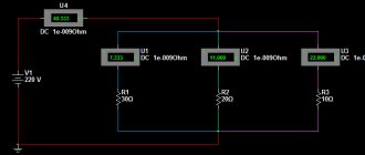
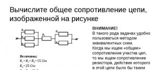
Let's consider an example with two resistors R1 and R2 connected in parallel. The resistance of the wire R3 and the power supply R0 is known. The value of EMF is also given - E.
We bring parallel branches to one number. For this situation, the formula applies:
R = (R1*R2) / (R1+R2)
We determine the resistance of the entire circuit through the sum R4 = R+R3.
We calculate the current:
It remains to find out the value of the voltage drop across the selected element:
Here the multiplier “R5” can be any R - from 1 to 4, depending on which particular circuit element needs to be calculated.
So, a resistor... The basic element of constructing an electrical circuit.
The job of a resistor is to limit the current flowing through the circuit. NOT in converting current into heat, but in limiting the current. That is, without a resistor, a large current flows through the circuit; if a resistor was built in, the current decreased. This is its work, in which this element of the electrical circuit produces heat.
Example with a light bulb
Let's look at the operation of a resistor using the example of a light bulb in the diagram below. We have a power source, a light bulb, and an ammeter that measures the current passing through the circuit. And Resistor. When there is no resistor in the circuit, a large current, for example, 0.75A, will flow through the light bulb along the circuit.
The light bulb burns brightly. They built a resistor into the circuit - the current had a difficult barrier to overcome; the current flowing through the circuit decreased to 0.2A. The light bulb burns less brightly. It is worth noting that the brightness with which the light bulb burns also depends on the voltage on it. The higher the voltage, the brighter it is.
In addition, a voltage drop occurs across the resistor. The barrier not only delays the current, but also “eats” part of the voltage applied by the power source to the circuit. Consider this fall in the figure below. We have a 12 volt power supply.
Just in case, an ammeter, two voltmeters in reserve, a light bulb and a resistor. We turn on the circuit without a resistor (on the left). The voltage at the light bulb is 12 volts. We connect the resistor - part of the voltage drops across it. The voltmeter (bottom right in the diagram) shows 5V.
The remaining 12V-5V=7V remained for the light bulb. The voltmeter on the light bulb showed 7V.
Of course, both examples are abstract, imprecise in terms of numbers and are designed to explain the essence of the process occurring in the resistor.
Resistor resistance unit
The main characteristic of a resistor is resistance. The unit of resistance is Ohm (Ohm, Ω). The greater the resistance, the more current it can limit, the more heat it generates, the more voltage drops across it.
Ohm's law for an electrical circuit
The fundamental law of all electricity. Connects Voltage (V), Current (I) and Resistance (R).
These symbols can be interpreted in human language in different ways. The main thing is to be able to apply it for each specific circuit. Let's use Ohm's Law for our resistor and light bulb circuit discussed above and calculate the resistance of the resistor that will limit the current from the 12V power supply to 0.2. In this case, we assume the resistance of the light bulb to be 0.
V=I*R => R=V/I => R= 12V / 0.2A => R=60Ohm
So. If you integrate a 60 Ohm resistor into a circuit with a power source and a light bulb whose resistance is 0, then the current flowing through the circuit will be 0.2A.
Resistor power characteristic
Microproger, know and remember! The resistor power parameter is one of the most important when constructing circuits for real devices.
The power of the electric current in any section of the circuit is equal to the product of the current flowing through this section and the voltage in this section of the circuit. P=I*U. The unit of measurement is 1W.
When current flows through a resistor, work is done to limit the electric current. When work is done, heat is released. The resistor dissipates this heat into the environment. But if the resistor does too much work and generates too much heat, it will no longer have time to dissipate the heat generated inside it, will heat up very much and burn out. What happens as a result of this incident depends on your personal luck quotient.
The power characteristic of a resistor is the maximum current power that it can withstand without overheating.
Resistor power calculation
Let's calculate the resistor power for our circuit with a light bulb. So. We have a current passing through the circuit (and therefore through the resistor) equal to 0.2A.
The voltage drop across the resistor is 5V (not 12V, not 7V, but precisely 5 - the same 5 that the voltmeter shows on the resistor). This means that the current power through the resistor is P=I*V=0.2A*5V=1W.
We conclude: the resistor for our circuit must have a maximum power of at least (or better, more) 1W. Otherwise it will overheat and fail.
AC Voltage Undervoltage
An alternating voltage of 220 Volts is widely used for domestic needs; due to its physical characteristics, it is much easier to reduce it to any value or carry out any other manipulations. In most cases, electrical appliances are already designed to be powered from the electrical network, but if they were purchased abroad, then the voltage level for them may differ significantly.
For example, devices brought from the USA are powered by 110V AC, and some craftsmen undertake to rewind the step-down transformer to obtain the desired level. But it should be noted that the pulse converter, which is often included with various power tools and devices, should not be rewound, as this will lead to its incorrect operation in the future. It is much more advisable to install an autotransformer or another at the rating you need in order to lower the voltage.
Using a transformer
Changing the voltage value using electrical machines is used in power supplies and rechargers. But to reduce the source voltage in this way, you can use different types of converter transformers:
- With output from the middle point - they can produce a potential difference of both 220V and half as much - 127V or 110V. From it you can take the set nominal value for the same 110V from the middle point. These are factory products that were installed en masse in old Soviet televisions and other devices. But this converter circuit has a significant drawback - if the integrity of the winding below the middle terminal is disrupted, then the output of the transformer will receive a rating of a much higher value.
Rice. 3. Step-down using a transformer with a tap from the midpoint
- An autotransformer is a universal electrical machine that can not only lower the voltage, but also increase it to the level you need. To do this, simply move the knob to the desired position and monitor the readings obtained on the voltmeter.
Rice. 4. Using an autotransformer
- A step-down transformer that converts 220V to the rating you need or from any other voltage of variable frequency. This method can be implemented using both ready-made transformer models and homemade ones. Due to the availability of a large number of tools and devices, today anyone can assemble a transformer with the given parameters at home. You can learn more about this from the corresponding article: https://www.asutpp.ru/transformator-svoimi-rukami.html
When choosing a specific model of electrical machine to reduce the voltage, pay attention to the characteristics of the specific model in relation to the devices that you want to power.
The most relevant parameters for transformers are:
- Power - the transformer must not only match the load connected to it, but also exceed it by at least 10 - 20%. Otherwise, the maximum current will lead to overheating of the transformer windings and further failure.
- Voltage rating – selected for both the primary and secondary circuits. Both parameters are equally important, since if you choose a model with an input voltage of 200 or 190V, you will get a proportionally larger value at the output when powered by 220V.
- Protection against electric shock - all windings and terminals from them must have sufficient insulation and protection from contact.
- Dust and moisture resistance class – determines the resistance of the equipment to environmental factors. In modern devices it is indicated by the IP index.
In addition, any voltage converter, even a pulse transformer, should be protected from short circuit currents and overloads in the windings. This will significantly reduce repair costs in the event of an emergency.
Using a resistor
To reduce the voltage, a voltage divider in the form of an active resistance is connected in series to the load circuit.
The main difficulty in adjusting the voltage on the connected device is the dependence on several parameters:
- voltage values;
- load resistance;
- source power.
If you step down from a household network, then it can be considered a source of infinite power and take this component as a constant. Then the resistor calculation will be performed using this method:
R = Uc/I - Rн,
Where
- R – resistor resistance;
- RН – resistance of the load device;
- I – current that must be provided in the nominal mode of the device;
- UC – network voltage.
After calculating the resistor value, you can select the appropriate model from the available range. It is worth noting that it is much more convenient to change the potential using a variable resistor connected to the circuit. By connecting it in series with the load, you can select the position in such a way as to reduce the voltage to the required value. However, this method cannot be called effective, since in addition to working in the device, electrical energy will simply be dissipated by a resistor, so this option is a temporary or one-time solution.