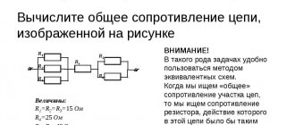
Alternating current is the main source of domestic and industrial power supply. When voltage is applied to consumers, resistance arises. The article will give a detailed explanation of what active resistance is in an AC circuit.
Additionally, a formula for calculating this value will be given, the varieties, conditions for an ideal chain and the main factors influencing the increase in these values will be described.
Alternating current
In order to understand what active resistance is, it is necessary to understand the phenomenon of alternating current itself. An alternating current is a type of current that continuously changes the direction of its flow. During flow, the alternating current potentials are constantly changing. This occurs due to the operation of the generator, or more precisely due to the interaction of the magnetic field with the copper winding. The movement can be clearly seen using an oscilloscope. Its shape resembles a sinusoid.
The role of alternating current is difficult to overestimate. Its main advantage is the ease of transmission from source to consumer, the ability to lower or increase the voltage using transformers. Also, alternating electric currents can be delivered to the consumer at much lower cost.
Resistance
Resistance is the ability of a conductor to slow down the passage of charged particles through its structure. This ability is affected by the material of the conductor, its thickness and length. The unit of electrical resistance is 1 ohm.
The calculation is made by passing a voltage of one volt through the conductor and a current equal to one ampere. In electrical diagrams, this parameter is indicated by the letter “R”.
Active resistance
Alternating current is delivered to the consumer for the purpose of converting it into other types of energy, for example, heat and light. In household networks, the use of single-phase alternating current predominates. When connecting a consumer, active resistance is created.
A simple AC circuit with active resistance includes a current generator and an ideal resistor. In this case, the necessary conditions for an ideal circuit must be met:
- Active resistance should not be equal to zero, a prerequisite.
- The capacitance and inductance of the circuit must be zero.
Also, for ideal active resistance the following conditions must be met:
- Ohm's law is observed for the instantaneous, rms and amplitude parameters of the circuit.
- The value is completely independent of amplitude fluctuations.
- There is no phase shift between current and voltage.
- An element under voltage releases a share of thermal energy, that is, it heats up.
All these conditions allow electrical devices to operate within precisely defined parameters with maximum efficiency. Any change may be caused by a lack of a reliable contact connection or a malfunction of the consumer itself.
In order to calculate the value of active resistance in a circuit, it is necessary to know the value of voltage and current. The formula used for calculation is: R=U/I. The formula consists of the following values:
- “R” - resistance, Ohm;
- “U” - voltage value, volts;
- “I” is the current value, ampere.
Then you can do a simple calculation. The consumer is an electric oven connected to a single-phase alternating current circuit:
- Circuit voltage is 240 volts.
- When measuring the current, a value of 4 amperes was obtained.
- R= 240/4=60 Ohm.
The calculated resistance value is not the final value. It is influenced primarily by the cross-section of the wires included in the circuit and the interaction pattern between the circuits of capacitive and semiconductor elements.
The active value of the circuit also causes a permanent loss of the original electrical energy, and also leads to a decrease in power.
Active and reactive resistance
In 11th grade it is known that direct electric current is the directional movement of charges along a conductor. Alternating current is the oscillation of electric charges around some average position. Moving or oscillating, the charges do work, which is released on the load resistance.
Rice. 1. Electric current.
The resistance at which the energy of the electric current is released in the form of heat is called active. In a DC circuit, resistances are only active. In an alternating current circuit there may be elements that resist the passage of current, but no power is released to them - such resistances are called reactive.
If active resistance converts the energy of electron motion into heat, then reactance stores part of the period the energy of electron motion (providing resistance), and part of the period releases the stored energy to electrons.
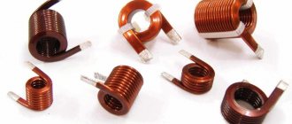
Resistors have active resistance; in addition, any real conductor also has some active resistance. Capacitors and inductors have reactance.
Rice. 2. Complete AC circuit.
Active capacitance
In a simple circuit, the magnitude of the active value also depends on the active capacitance. For ideal capacitance, there must be a capacitor in the circuit under alternating voltage. The ideal capacitor is designated by the letter "C".
To obtain an ideal circuit with active capacitance, the following conditions must be met:
- Active inductance and resistance must be 0.
- The capacitance of the capacitor itself in the circuit must be greater than 0.
Under these conditions, the electrical circuit acquires the following features:
- Ohm's law is observed without the slightest deviation.
- There is a capacitance "X" for alternating current.
- A nonlinear decrease in capacitance is observed with increasing oscillation frequency.
- There is a phase shift of up to 90 degrees between voltage and current.
- Circuit capacity is not constant. The reason lies in the periodic accumulation and release of energy.
An alternating current circuit with active capacitance can be supplemented with inductance. To create inductance, an inductor is connected to the circuit. The coil also adds its share of resistance to the overall circuit. With this connection, inductive reactance appears in the circuit. Both elements: the coil and the capacitor are not final consumers of energy. These elements are not under constant voltage; their work is based on the accumulation and release of current into the circuit.
Reactance of the inductor.
When alternating current flows I
in a coil, a magnetic field creates an EMF in its turns, which prevents the current from changing. When the current increases, the EMF is negative and prevents the current from increasing; when it decreases, it is positive and prevents its decrease, thus resisting the change in current throughout the entire period.
U is formed at the terminals of the inductor in antiphase
, suppressing EMF, equal to it in amplitude and opposite in sign.
When the current passes through zero, the amplitude of the EMF reaches its maximum value, which forms a discrepancy in time between the current and voltage of 1/4 of the period.
U is applied to the terminals of the inductor
, the current cannot start instantly due to the counter-emf equal to
-U
, therefore the current in the inductance will always lag behind the voltage by an angle of 90°. The shift at the lagging current is called positive.
Let us write down the expression for the instantaneous voltage value u
based on the emf (
ε
), which is proportional to the inductance
L
and the rate of change of current:
u = -ε = L(di/dt)
. From here we express the sinusoidal current.
Integral of the function sin(t)
will be
-cos(t)
or an equal function
sin(t-π/2)
.
The differential dt
of the function
sin(ωt)
will leave the sign of the integral by the factor 1
/ω
.
As a result, we obtain an expression for the instantaneous value of the current with a shift from the voltage function by an angle π/2
(90°).
In this case, for the root-mean-square values of U
and
I,
As a result, we have a dependence of sinusoidal current on voltage according to Ohm’s Law, where in the denominator instead of R
expression
ωL
, which is the reactance:
The reactance of inductances is called inductive.
Power
In the presence of active resistance, the power of this circuit is significantly reduced. This value depends on the rate of voltage reduction and electrical energy conversion. In the electrical diagram, power is designated by the letter “P”.
In order to achieve a minimal reduction in the average and instantaneous powers that are formed at the moment of the appearance of active resistance, voltage reduction and energy conversion, it is necessary that the simplest circuits consist of ideal elements with high electrical conductivity.
What is apparent power using a simple RL circuit as an example?
Graphs of changes in instantaneous values u, i:
Graphs of changes in instantaneous values u, i:
φ - phase shift between current and voltage
The equation for S will take the following form
Let's substitute and replace the amplitude values with actual values:
The value S is considered as the sum of two quantities, where
and - instantaneous active and reactive powers in RL sections.
Graphs p,q,s:
As we can see from the graph, the presence of an inductive component entailed the appearance of a negative part in the total power (shaded part of the graph), which reduces its average value. This occurs due to a phase shift; at some point in time, the current and voltage are in antiphase, so a negative S value appears.
Final expressions for effective values:
The active component of the network is expressed in watts (W), and the reactive component in reactive volt-amperes (var).
The total power of the network S is determined by the nominal data of the generator. For the generator it is determined by the expression:
For normal operation of the generator, the current in the windings and the voltage at the terminals should not exceed the rated values In, Un. For the generator, the values of P and S are the same, but in practice it was agreed to express S in volt-amperes (VA).
Also, the network energy can be expressed through each component separately:
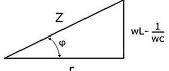
Where S, P, Q are the active, reactive and impedance of the network, respectively. They form a power triangle:
Power triangle with predominantly inductive load
If we recall the Pythagorean theorem, then from a right triangle we can obtain the following expression:
The reactive component in the triangle is positive (QL) when the current lags behind the voltage, and negative (QC) when it leads:
Power triangle with dominant capacitive load
For the reactive component of the network, the algebraic expression is valid:
From which it follows that inductive and capacitive energy are interchangeable. That is, if you want to reduce the influence of the inductive part of the circuit, you need to add capacitance, and vice versa. Below is an example of this diagram:
Reactive component compensation circuit
The phasor diagram shows the effect of the capacitor on cosφ. As you can see, when the capacitor is turned on, cosφ2> cosφ1 and Il
Vector diagram
The relationship between total and reactive energy is expressed:
From here:
сosφ is the power factor. it shows what proportion of the total energy is active energy. The closer it is to 1, the more useful energy is consumed from the network.
Addiction
The amount of active resistance largely depends on the diameter of the conductors. When high-frequency currents are applied, the resistance of the conductor can be reduced only if its surface layer is much thinner than the main one. In order to achieve an ideal cross-section, this layer must consist of a material with very high conductivity, such as gold or silver. This effect occurs due to the interaction of voltage and the magnetic field formed by it. The field strongly influences the current flowing through the conductor and pushes it to the surface layer. Thus, closer to the surface of the conductor, the conductivity decreases and becomes critically small in its upper layer.
The following effects are also present: leakage losses and dielectric losses. Both effects are associated with the presence of a capacitor in the circuit. Dielectric losses occur due to an increase in the temperature of the dielectric inside the capacitor. Leakage loss occurs due to the breakdown fraction of the capacitor insulator.
Hysteresis. This is also a type of AC energy loss. This loss occurs when a magnetic field forms around metal objects. Electromagnetic influence leads to heating of the metal, which means energy conversion.
The last leakage factor is radio emission. Radio waves appear due to a strong magnetic field and its interaction with the metals of the circuit. For suppression, especially in radio equipment, screens are used that absorb part of the field and repel the rest.
Calculation
To find out the active power indicator, you need to know the total power; the following formula is used to calculate it:
S = U\I, where U is the network voltage, and I is the network current.
The same calculation is performed when calculating the energy transfer level of the coil with a symmetrical connection. The diagram looks like this:
Symmetrical load diagram
The calculation of active power takes into account the phase angle or coefficient (cos φ), then:
S = U * I * cos φ.
A very important factor is that this electrical quantity can be either positive or negative. It depends on what characteristics cos φ has. If the phase shift angle of a sinusoidal current is in the range from 0 to 90 degrees, then the active power is positive, if from 0 to -90, then it is negative. The rule is valid only for synchronous (sinusoidal) current (used to operate an asynchronous motor or machine tool equipment).
Also, one of the characteristic features of this characteristic is that in a three-phase circuit (for example, a transformer or generator), the active indicator is completely generated at the output.
Three-phase network calculation
Maximum and active power is denoted by P, reactive power by Q.
Due to the fact that reactive is determined by the movement and energy of the magnetic field, its formula (taking into account the phase shift angle) has the following form:
QL = ULI = I2xL
For non-sinusoidal current it is very difficult to select standard network parameters. To determine the required characteristics for the purpose of calculating active and reactive power, various measuring devices are used. This is a voltmeter, ammeter and others. Based on the load level, the desired formula is selected.
Due to the fact that the reactive and active characteristics are related to the total power, their relationship (balance) is as follows:
S = √P2 + Q2, and all this equals U*I.
But if the current passes directly through the reactance. There are no losses in the network. This is determined by the inductive inductive component - C and resistance - L. These indicators are calculated using the formulas:
Inductance resistance: xL = ωL = 2πfL,
Capacitance resistance: xc = 1/(ωC) = 1/(2πfC).
To determine the ratio of active and reactive power, a special coefficient is used. This is a very important parameter by which you can determine what part of the energy is used for other purposes or is “lost” during operation of the device.
If there is an active reactive component in the network, the power factor must be calculated. This quantity has no units of measurement; it characterizes a specific current consumer if the electrical system contains reactive elements. Using this indicator, it becomes clear in which direction and how the energy shifts relative to the network voltage. To do this you will need a voltage triangle diagram:
Stress Triangle Diagram
For example, if there is a capacitor, the coefficient formula is as follows:
cos φ = r/z = P/S
To obtain the most accurate results, it is recommended not to round the data obtained.
Metering
Resistance measurement is carried out in the following ways:
- Voltmeter and ammeter. Using these devices, current and voltage values are measured, and then a calculation is made using the formula described above.
- Logometer. This is a device for measuring resistance under high voltage and high frequency. Its main advantage is the strong elimination of dependencies and errors.
- Ohmmeter. The device is used for signal amplifier type measurements only. When using an ohmmeter, a high error is taken into account, which can reach 5%. Conventional electronic ohmmeters are not suitable for measuring active resistance.
Formula for calculating reactance
In general, for coil-type parts the following expressions are used:
X = L*w = 2* π*f*L.
For capacitors the following formulas are used:
X = 1/(w*C)= 1/(2* π*f*C).
For a specific element, the required parameters of which are known, the value can be calculated using an online calculator. You will need to enter the required data in the form and click on the button that initiates calculations.
The ability to calculate this component of resistance will help you find out the amount of heat loss at the loads used. By connecting a capacitor in parallel with a suitable capacitance, the problem of energy losses due to inductive loads can be solved.