When an inductor is connected to an alternating current circuit, changes in this current occur under the influence of a continuously changing voltage. In turn, these changes cause the generation of a magnetic field that periodically increases or decreases. Under its influence, a counter voltage is induced in the coil, preventing changes in current. Thus, the flow of current occurs under a continuous counteraction, called inductive reactance.
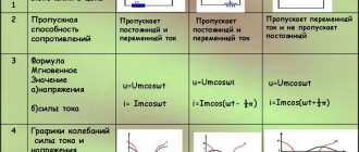
Types of resistance and their features
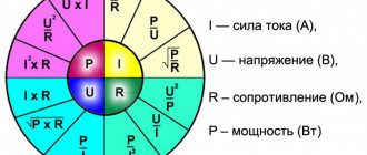
If there is a constant voltage in the circuit, then, knowing its resistance, you can find out the current strength using Ohm's law. It says that the strength of the current is proportional to the voltage that causes it. The proportionality factor represents normal resistance. It is usually called active.
If the voltage is constant, then the resistance will only be active. Its value determines how much energy of the electric field is converted into heat, that is, irretrievably lost. Therefore, when working with cables SIP-3 1×50, SIP-2 3×70 and others, you must remember that energy losses due to active resistance can be significant.
The use of alternating current is more common. It occurs under the influence of voltage that changes cyclically according to a sinusoidal law. Such a current generates reactance, which complements the action of the active one. There are two types of reactance of different nature - based on inductance or capacitance. Their distinctive feature is that they do not contribute to the waste of electricity, but to convert it into another form.
It must be taken into account that the use of various types of cables is associated not only with the presence of active resistance, but also reactive one. For example, cables SIP-3 1×50, SIP-2 3×70, AC-95 can be used in electrical networks with active, inductive, and capacitive resistance.
To understand what inductive reactance is, you can imagine a circuit in which there is a coil connected to an alternating current source. As you know, voltage changes according to a sinusoidal law. With these changes, the coil will create a magnetic field, which will, in particular, affect the current flowing through it. According to the nature of the magnetic field, when the current decreases, the magnetic field contributes to its increase, and when it increases, the opposite effect is observed. In addition, the AC circuit with active resistance wastes energy to generate heat.
In practice, we are talking about the action of inductive reactance, which provides a phase shift between current and voltage. The movement of charges creates a field, which in turn prevents the current from changing. Such resistance is present not only in coils, but also, for example, when using SIP-2 3x70 cable.
Capacitance has a different nature. To explain, consider a circuit consisting of an AC source and a capacitor. The latter is a part in which two surfaces are parallel to each other and do not have direct electrical contact.
When using direct current, charges accumulate on the plates of the capacitor: one is positive, and the other is negative. The electric field due to the accumulated charge is a source that counteracts the current. Therefore, a capacitor in a DC circuit has an infinitely large resistance. The current does not pass through the dielectric separating the capacitor plates.
In an alternating current circuit, a capacitor is cyclically charged and discharged, ensuring the movement of electrical charges. This process in an alternating current circuit with active and reactive resistance will occur with a delay relative to the sinusoidal voltage change. Thus, the capacitor represents a finite resistance, called capacitive.
The difference between capacitive and inductive reactance is that direct current flows through an inductive coil, but cannot pass through a capacitor. However, alternating current can flow in both circuits without any problem.
Practical use
One common use of coil inductance is to create filters. In complex systems, noise at high frequencies may occur, which reduces the quality of signal transmission. This may be relevant, for example, for acoustic systems that depend on the quality of reproduction of sound signals. In this case, it helps that the inductive reactance is determined by the frequency of the current.
Electric currents of different frequencies passing through the coil cause different inductive reactance in it. The higher the alternating current frequency, the greater it is. At zero frequency, that is, steady constant current, the inductive reactance is also zero.
The signals are passed through a filter with an inductive reactance that prevents signals of unwanted frequencies from passing through. To block the path of low-frequency sound signals, coils with steel cores are used, while high-frequency ones are used without cores. Such coils are called chokes, low and high frequency, respectively.
In the situation under consideration, it is convenient to simultaneously use capacitive reactance, which also depends on the frequency of the current. But it decreases with its increase. Thus, using filters you can get rid of unwanted noise signals.
Another important application of the phenomenon under consideration is a transformer. The same self-induction that inhibits the passage of current plays a positive role in this device due to the resistance created.
A transformer uses a core and two windings. An alternating supply voltage is supplied to the primary winding, and an induced current is generated on the secondary winding. The presence of induction currents of a certain magnitude is necessary for the operation of many electrical appliances.
Using a transformer, you can, for example, convert 220 V mains power into 12 V, which is necessary to power a stereo system. This adjustment is determined by the ratio of the number of turns on the primary and secondary windings.
The coil is a source of EMF. This feature is used in induction cookers. The electromagnetic waves generated by the coil heat the cookware and their contents. Furnaces in steel mills operate on the same principle.
Knowing what the phenomenon of inductive reactance is, it can be used to calculate the parameters of various electrical and power equipment.
What is called inductive reactance
When an alternating voltage is applied to a coil, the current passing through it changes according to the applied voltage. This causes a change in the magnetic field, creating an electromotive force that interferes with what is happening.
Measuring circuit
In such a circuit there is a dependence of electrical parameters on two types: conventional and inductive. They are designated, respectively, as R and XL.
On a normal one, power is released. However, on reactive elements it is zero. This is due to the constant change in direction of the alternating current.
During one oscillation period, energy is pumped into the coil twice and returned to the source the same number of times.
Definition of inductance
Applications of inductors
Inductors (together with capacitors and/or resistors) are used to construct various circuits with frequency-dependent properties, in particular filters, feedback circuits, oscillatory circuits, etc.
Inductors are used in switching regulators as an element that stores energy and converts voltage levels.
Two or more inductively coupled coils form a transformer.
An inductor, powered by a pulsed current from a transistor switch, is sometimes used as a high-voltage source of low power in low-current circuits when creating a separate high supply voltage in the power supply is impossible or economically impractical. In this case, due to self-induction, high voltage surges appear on the coil, which can be used in the circuit, for example, by rectifying and smoothing.
Coils are also used as electromagnets.
Coils are used as an energy source to excite inductively coupled plasma.
For radio communications - emission and reception of electromagnetic waves (magnetic antenna, ring antenna).
- Loop antenna
- Induction loop
For heating electrically conductive materials in induction furnaces.
As a displacement sensor: the change in the inductance of the coil can be varied over a wide range by moving (pulling out) the core.
The inductor is used in inductive magnetic field sensors. Induction magnetometers were developed and widely used during World War II.
The principle of operation of inductive reactance of lines
It is inductance that is recognized as the main characteristic for coils, along with a similar indicator for their windings. R of the reactive type, manifested under the influence of self-induction EMF, grows in direct proportion to the frequency of the current.
The reactive and active components determine the total resistance, which can be represented as the sum of the squares of each indicator.
Special tables will help you quickly cope with the task of calculating nominal indicators. They contain all the main characteristics for the most common conductors. But in practice, it is often necessary to find out X for a section with a specific length. In this case, the main tool is the already given expression
Resistivity
Resistivity (ρ) is a unit that shows the ability of a conductor to impede the passage of electric current.
It can be used to evaluate the parameters of electrical conductors made of different materials. ρ of the conductor always increases with increasing length and decreasing cross-section; in the international system, the length of the conductor is 1 meter and the cross-section is -1 mm2.
Similar: Problems with LED TV: there is sound, but no picture
What factors does resistance depend on?
Changing the current creates an electromagnetic field of variable intensity. The result of its effect on the conductor is to counteract the current change that occurs.
This opposition is called reactance. There are two types of it: inductive and capacitive. The first is created when there is an inductive element in the circuit, the second - a capacitor.
In a situation where a coil is present in the circuit, its response increases as the frequency increases.
Circuit in which induction occurs
When its inductance decreases, the opposing force also becomes less. As it increases, it increases.
Inductive reactance is significantly related to the shape the conductor takes. It is also present on a separate wire lying straight. However, if there is another one nearby, it will have an additional effect, which will affect the value under consideration.
The characteristic of an individual wire under consideration can be determined depending on its thickness, but it is in no way related to its cross-section.
The principle of operation of electromotive force
Capacitance
In a circuit containing a capacitance and an alternating current source, charge changes occur. Capacitors that have maximum energy when fully charged have this capacitance. The capacitance voltage creates a resistance that opposes the flow of alternating current, which is considered reactive. As a result of interaction, the capacitor and the current source constantly exchange energy.
The design of the capacitor includes two or more current-conducting plates, separated by layers of dielectric. This separation prevents direct current from passing through the capacitor. Alternating current can pass through a capacitive device, deviating from its original value.
Changes in alternating current occur under the influence of capacitance. To better understand the operation scheme, let’s find and consider the operating principle of this phenomenon. An alternating voltage applied to a capacitor changes in the form of a sine wave. Under its influence, a surge is observed on the plates, and at the same time charges of electricity with opposite signs accumulate here. Their total number is limited by the capacity of the device and its dimensions. The higher the device capacity, the longer it takes to charge.
At the moment the half-cycle of oscillation changes, the voltage on the plates of the capacitor changes its polarity to the opposite value, the potentials also change, and the charges of the plates are recharged. Due to this, it is possible to create a flow of primary current and find a way to counteract its passage, while decreasing the magnitude and shifting the angle. Charging the plates allows the current passing through the capacitor to lead the voltage by 90.
Inductor
It consists of an insulated wire wound repeatedly around a core.
Typically the frame has a cylindrical or toroidal shape.
Inductance is considered as the main characteristic of the coil. This quality expresses the ability of an element to convert alternating current into a magnetic field.
Important! Magnetic properties exist even in a single wire, provided that the current passing through it changes. The influence of the field is directed so as to counteract its change. If it increases, the field will slow it down, and if it weakens, it will strengthen it.
Inductors
Determining the direction of the field lines obeys the “rule of thumb”: if the hand clenched into a fist has the thumb pointing in the direction of the change in current strength, then the closed fingers indicate the direction of the field lines.
Thus, if the wire is repeatedly wound on a cylindrical base, then the power lines from different turns add up and pass through the axis.
It will be interesting➡ Making conductive glue from scrap materials
In order to increase the inductance many times over, a core of ferromagnetic material is placed in the center of the cylinder.
Operating principle
The principle of operation of an inductor is the creation and interaction of magnetic flux by the turns of the winding.
If we take a single turn in a simplified case, then when an electric current passes through it, a magnetic flux is created moving along the surface of the circuit, proportional to the magnitude of the current and the value of the inductance:
Ф=L·I, where
Ф – magnetic flux;
L – inductance;
I – current strength.
Important! In the vast majority of cases, coils are a multi-turn design, therefore they form a complex surface and parameter calculations are carried out in a simplified form. Magnetic flux of solenoidal coil
Magnetic flux of solenoidal coil
The formation of a magnetic flux by each of the turns and its interaction with the others (magnetic induction) leads to the emergence of self-induction emf, which consists in the fact that when the magnitude of the flowing current in the coil changes, an emf is formed and, accordingly, a current directed to counteract the changes.
In the case of alternating current, this results in the current phase lagging behind the voltage phase by 90°. This property is used in reactance compensators (reactors), chokes, and delay lines.
Important! The magnitude of the self-induction EMF is directly proportional to the rate of change of current. This allows the development of high-voltage voltage sources
An automobile ignition coil consists of two windings - low voltage and high voltage. When the power is disconnected in the low-voltage winding, a self-induction EMF pulse is formed in it, which reaches tens of thousands of volts in the high-voltage winding.
Automotive ignition coil
The inductor resistance has two components:
- Inductive reactance;
- Loss resistance.
Inductive reactance (reactance, impedance) depends on the frequency of the flowing current:
XL = 2·π·f·L, where
π – 3.14;
f – frequency;
L – inductance.
Loss resistance includes:
- Wire losses (coil resistance);
- Eddy current losses;
- Core loss;
- Dielectric losses.
Important! Some losses are also introduced by distributed capacitance, which is reduced by using a special winding configuration and dividing it into sections. The main share of losses comes from active resistance
The main share of losses comes from active resistance.
Formulas, dependencies and types of inductance
Electrical inductance L is a quantity equal to the proportionality coefficient between the current I flowing in a closed circuit and the magnetic flux it creates, otherwise called the flux linkage Y:
Y = LI.
If voltage is applied to the coil terminals for some time, current I will begin to flow in it and a magnetic field will form. The lower the inductance L, the faster this process occurs. As a result, the two-terminal network under consideration will accumulate a certain amount of potential energy. When the power is turned off, it will try to return it. As a result, a self-inductive emf E is formed at the coil terminals, which is many times higher than the initially applied voltage. A similar technology was previously used in magnetos of internal combustion engine ignition systems, and is now widely found in boost DC-DC converters.
Formula for self-induction EMF, here t is the time during which the current I decreases to zero. Simple DC-DC boost converter
A coil (also known as a choke) is a radio component with pronounced inductance, because that’s exactly what it was created for. However, in principle all elements have this property. For example, a capacitor, a resistor, a cable, just a piece of wire, and even the human body also has some inductance. In the calculations of RF circuits, this must be taken into account.
Important! When measuring inductance with a specialized device, it is worth remembering that you cannot hold both of its terminals with your hands. Otherwise, the readings may change and be incorrect. This is caused by the inclusion of the human body with its own inductance in the measured circuit.
Relationship between phases U and I on XL
Since the active resistance of the coil is equal to zero (purely inductive resistance), then all the voltage applied by the generator to the coil is used to overcome the e. d.s. self-inductance of the coil. This means that the graph of the voltage applied by the generator to the coil is equal in amplitude to the graph of e. d.s. self-induction of the coil and is in antiphase with it.
The voltage applied by the generator to the purely inductive reactance and the current flowing from the generator through the purely inductive reactance are shifted in phase by 90 0, i.e. that is, the voltage leads the current by 90 0.
In addition to inductive reactance, a real coil also has active resistance. These resistances should be considered connected in series.
At the active resistance of the coil, the voltage applied by the generator and the current coming from the generator are in phase.
On a purely inductive reactance, the voltage applied by the generator and the current coming from the generator are shifted in phase by 90 0. Voltage leads current by 90 0. The resulting voltage applied by the generator to the coil is determined by the parallelogram rule.
click on the picture to enlarge
The resulting voltage applied by the generator to the coil always leads the current by an angle less than 90 0.
The magnitude of the angle φ depends on the values of the active and inductive resistance of the coil.
About the resulting coil resistance
The resulting resistance of the coil cannot be found by summing the values of its active and reactive resistances
.
The resulting coil resistance Z is
Inductor in an AC circuit
An inductor in an AC circuit behaves differently than a resistor. If resistors simply resist the flow of electrons (the voltage across them is directly proportional to the current), then inductors resist the change in current passing through them (the voltage across them is directly proportional to the rate of change of current). According to Lenz's Law, the induced voltage always has a polarity that attempts to maintain the current value of the current. That is, if the current increases, the induced voltage will “slow down” the flow of electrons; if the current decreases, the voltage polarity will reverse and will “help” the electron flow remain at the same level. This resistance to a change in current is called reactance.
The mathematical relationship between the voltage across an inductor and the rate of change of current through it is as follows:
The ratio di/dt is the rate of change of instantaneous current (i) over time, and is measured in amperes per second. Inductance (L) is measured in Henry, and instantaneous voltage (u) is measured in volts. To show what happens with alternating current, let's analyze a simple inductive circuit:
A simple inductive circuit: the coil current lags the voltage by 90 o.
If we plot the current and voltage for this simple circuit, it will look something like this:
As you remember, a change in voltage across an inductor is a response to a change in the current passing through it. From this we can conclude that the instantaneous voltage is zero whenever the instantaneous value of the current is at its peak (zero change, or zero slope of the current sine wave), and the instantaneous voltage is equal to its peak value whenever the instantaneous current is at the points of maximum change (points of steepest slope of the current wave at which it crosses the zero line). All this leads to the fact that the voltage wave is 90 o out of phase with the current wave. The graph shows how the voltage wave gives a “head start” to the current wave: voltage “leads” the current, and the current “lags” behind the voltage.
Read also: What to make a chisel for metal from
If we plot the power values of our circuit on this graph, then everything will become even more interesting:
Since instantaneous power is the product of instantaneous voltage and instantaneous current (p = iu), it will be zero if the instantaneous voltage or current is zero. Whenever the instantaneous current and voltage values are positive (above the zero line), the power will also be positive. Similar to the example with a resistive circuit, the power will take a positive value even if the instantaneous current and voltage have negative values (below the zero line). However, due to the fact that the voltage and current waves are 90 o out of phase, there are cases when the current is positive and the voltage is negative (or vice versa), resulting in negative instantaneous power values.
But what is negative power? Negative power means that the inductor is releasing energy back into the circuit. Positive power means that the inductor absorbs energy from the circuit. Since positive and negative power cycles are equal in magnitude and duration, over the course of a complete cycle, the inductor puts back into the circuit as much power as it draws from it. In practical terms, this means that the reactance of a coil does not dissipate any energy, which is different from the reactance of a resistor, which dissipates energy as heat. However, all of the above is true only for ideal inductors, the wires of which have no resistance.
The resistance of the inductor, which changes the strength of the current, is interpreted as the resistance to the alternating current as a whole, which, by definition, constantly changes instantaneous magnitude and direction. This AC resistance is similar to normal resistance, but differs from it in that it always results in a phase shift between current and voltage, and also dissipates zero power. Due to these differences, this resistance has a slightly different name - reactance. Reactance, like regular reactance, is measured in Ohms, only it is denoted by the symbol X, not R. To be more specific, the reactance of an inductor is usually denoted by the capital letter X with the letter L as an index: XL.
Since the voltage across the inductor is proportional to the rate of change of current, it will be greater for rapidly changing currents and less for slower changing currents. This means that the reactance of any inductor (in Ohms) is directly proportional to the frequency of the alternating current. The exact formula for calculating reactance is as follows:
If a coil with an inductance of 10 mH is exposed to frequencies of 60, 120 and 2500 Hz, then its reactance will take the following values:
In the reactance equation, the expression “2πf” is important. It means the number in radians per second that characterizes the "rotation" of alternating current (one complete cycle of alternating current represents one complete rotation). A radian is a unit of measurement for angles: there are 2π radians in one full circle, just as there are 360 o in one. If the alternator is two-pole, then it will produce one complete cycle for each complete revolution of the shaft, which will mean 2π radians or 360 o. If the constant 2π is multiplied by the frequency in hertz (cycles per second), the result is a number in radians per second known as the angular (cyclic) frequency of the alternating current.
In addition to the expression 2πf, the angular frequency of alternating current can be denoted by the lowercase Greek letter ω (Omega). In this case, the formula XL = 2πfL can be written as XL = ωL.
It is important to understand that the angular frequency is an expression of how quickly the wave completes its cycle, which is equal to 2π radians. It does not necessarily represent the actual shaft speed of the generator producing the alternating current. If the generator has more than two poles, its angular frequency will be a multiple of the shaft speed. For this reason, ω is sometimes expressed in units of electrical radians per second to distinguish it from mechanical motion.
With any method of expressing the angular frequency, it is obvious that it is directly proportional to the reactance of the inductor. As the frequency of the alternating current (or the rotation speed of the generator shaft) increases, the inductor will provide greater resistance to the passage of current and vice versa. The alternating current in a simple inductive circuit is equal to the voltage (in Volts) divided by the reactance of the inductor (in Ohms). As you can see, this is similar to the fact that AC or DC current in a simple resistive circuit is equal to the voltage (in Volts) divided by the resistance (in Ohms). As an example, let's consider the following diagram:
However, we must keep in mind that voltage and current have different phases. As mentioned earlier, voltage has a phase shift of +90 o with respect to current (figure below). If we represent the phase angles of voltage and current mathematically (in the form of complex numbers), we will see that the inductor's resistance to alternating current has the following phase angle:
The current across the inductor lags the voltage by 90 o.
Mathematically, we can say that the phase angle of the inductor's resistance to alternating current is 90 o. The phase angle of current reactance is very important in circuit analysis. This importance is especially evident when analyzing complex alternating current circuits, where reactive and simple resistances interact with each other. It will also prove useful for representing the resistance of any component to electrical current in terms of complex numbers (rather than scalar quantities of resistance and reactance).
Calculation of the inductive reactance of the coil
Any inductance, incl. coil provides some resistance to alternating current. How to calculate it was described above. From the formula XL=2pfL it is clear that the resistance of the inductor primarily depends on the frequency of the current flowing through it and its inductance. Moreover, the relationship with both parameters is directly proportional.
Impedance
Frequency is a characteristic of the external environment; the inductance of the coil depends on a number of its geometric properties:
L=u0urN2S/l,
Where:
- u0 – magnetic permeability of vacuum – 4p*10-7 H/m;
- ur – relative permeability of the core;
- N – number of throttle turns;
- S – its cross section in m2;
- l is the length of the coil in meters.
Having the above-described formulas and information about the material and dimensions of the coil, you can fairly accurately estimate its inductive reactance without any measuring instruments.
Additional Information. Some digital multimeters have an inductance mode. This feature is rare, but sometimes it turns out to be very useful. Therefore, when choosing a device, you should pay attention to whether it is capable of measuring inductance.
Calculation of coil parameters
We have to consider different options when making calculations. The calculation of inductance depends on the initial data and the specified final parameters.
Calculation of L depending on the given design
If the initial parameters are: w, D of the frame and the length of the wound wire, then the formula for calculation is:
L = 0.01*D*w2/(l/D) + 0.46,
Where:
- D – frame diameter, cm;
- w – number of turns;
- l – winding length, cm;
- L – inductance, µH.
Substituting numerical values into the formula, the value of L is obtained.
Calculation of the number of turns by inductance
Knowing frame D and L, the number of turns in the coil is calculated, the formula looks like:
w = 32*√(L*D),
Where:
- L – inductance, µH;
- D – frame diameter, mm.
If the length of the conductor wound in a row and its diameter are taken as the initial parameters, then the number of turns is found using the formula:
w = l/d,
Where:
- l – winding length, mm;
- d – wire diameter, mm.
Wire diameter measurements are carried out with a ruler or caliper.
Calculation of inductance of a straight wire
When planning to find L of a round straight conductor, we turn to the approximate formula:
L = (μ0/2π)*l*( μe*ln(l/r) + 1/4* μi,
Where:
- μ0 – magnetic constant;
- μe – relative magnetic permeability (RMP) of the medium (for vacuum – 1);
- μi – conductor OMF;
- l – wire length;
- r is the radius of the wire.
The formula is valid for a long conductor.
Calculation of single-layer winding
Single-layer chokes without a core can be easily and quickly calculated using an online calculator, in the window of which you can enter all known characteristics, and the program will display the value L.
Calculations are also carried out manually, using a mathematical expression. It looks like:
L = D2*n2/45D + 100*l,
Where:
- D – coil diameter, cm;
- l – length of the wound wire, cm;
- n – number of turns.
The formula is suitable for calculating L chokes without ferrite cores.
Single layer coil turn to turn
Core choke
If there is a core, its size and shape should be taken into account. In the case of identical coils, the inductance is greater in the one located on the core.
Calculation of single-layer winding with core
Multilayer winding
Features of the calculation with this method of winding wire are that you need to take into account its thickness. The formula for a coreless choke is:
N²=(L*(3Dk+9l+10t))/0.008Dk²,
Where:
- Dk – total diameter (diameter of frame and winding);
- t – layer thickness;
- l is the length of the wound wire.
All values are substituted in mm, the value of L is in µH.
Multilayer winding
Inductance in a DC circuit
To better understand the processes occurring in the coil, let’s consider what happens in the coil when a constant voltage is applied to it.
When a power source is connected to the coil, a current begins to flow in it, which creates a magnetic field around it. Magnetic field lines propagate through the turns of the coil outward, crossing them, and thus form a self-induction emf. This EMF, according to Lenz's rule, will prevent an instantaneous increase in current in the coil. The current increases gradually, according to an exponential law. After a short period of time, the transient process ends and the current reaches its normal value. The duration of the current rise in seconds is determined by the formula:
t=3L/R,
where L is the inductance of the coil in henry, and R is the total resistance of the entire circuit in ohms. If, for example, the inductance of the coil is L=0.6 G, and the resistance of the circuit is R=60 Ohm, then the duration of the transient process will be equal to: t=3•0.6/60=0.03 sec.
It will be interesting➡ What is an electric charge and what are its properties?
When the battery is disconnected from the inductance coil, a transient process also occurs (such an experiment with the primary winding of a transformer is shown on the “Electromagnetism” page, Fig. e). In this case, the magnetic lines of force will approach the center of the coil, again crossing its turns. A self-induction emf is created, which is no longer directed against the current, but (again according to Lenz’s rule) coinciding with the direction of the interrupted current.
If the coil has a large inductance (in our experience the coil is the primary winding of a transformer with a large number of turns and a significant iron core) and a large current flows through it, then the self-inductive emf appearing at the ends of the inductor can reach a value many times greater than the source voltage nutrition. This is explained by the fact that when the supply network is opened, the energy stored in the magnetic field of the coil does not disappear, but turns into current. The voltage between the ends of the inductor can reach such values that can lead to a breakdown between the windings, as well as failure of semiconductor devices. This must be taken into account in practice when working with devices that have coils with high inductance through which significant current passes.
Coil device
Closer to the idealized element - inductance - is a real element of an electronic circuit - an inductive coil. Unlike inductance, the inductive coil also stores the energy of the electronic field and converts electronic energy into other types of energy, namely thermal. Quantitatively, the ability of the real and idealized parts of an electronic circuit to store magnetic field energy is characterized by a parameter called inductance.
Thus, the term “inductance” is used as the name of an idealized element of an electronic circuit, as the name of a parameter that quantitatively characterizes the characteristics of this element, and as the name of the main parameter of an inductive coil.
The relationship between voltage and current in an inductive coil is determined by the law of electrical induction, from which it follows that when the magnetic flux passing through the inductive coil changes, an electromotive force e is induced in it, proportional to the speed of the coil flux linkage configuration ψ and directed in such a way that the current caused by it tends to prevent magnetic flux from changing:
e = - dψ / dt
In SI units, magnetic flux and flux linkage are expressed in Webers (Wb).
Interesting read: instructions on how to ring a transistor.
The magnetic flux F, penetrating any of the turns of the coil, in the general case can contain two components: the magnetic flux of self-induction Fsi and the magnetic flux of external fields Fvp: F - Fsi + Fvp.
The first component is the magnetic flux caused by the current flowing through the coil, the second is determined by magnetic fields, the existence of which is not related to the coil current - the Earth’s magnetic field, the magnetic fields of other coils and permanent magnets. If the 2nd component of the magnetic flux is caused by the magnetic field of another coil, then it is called mutual induction magnetic flux.
The flux linkage of the coil ψ, as well as the magnetic flux Ф, can be represented as the sum of two components: the flux linkage of self-induction ψsi, and the flux linkage of external fields ψvp
ψ= ψsi + ψvp
The EMF e induced in the inductive coil, in turn, can be represented as the sum of the self-induction EMF, which is caused by the configuration of the magnetic flux of self-induction, and the EMF caused by the configuration of the magnetic flux of the fields external to the coil:
e = esi + evp,
here esi is the EMF of self-induction, evp is the EMF of external fields.
If the magnetic fluxes of the fields external to the inductive coil are equal to zero and only the self-induction flux penetrates the coil, then only the self-induction emf is induced in the coil.
Inductance in AC circuit
For experiments with direct current, the inductor is wound with a thin wire with a large number of turns. This is done so that when voltage is applied to it from a powerful power source, the turns of the coil do not burn out, because when winding turns with a thick wire, the resistance will be small, and the current through it will be large (according to Ohm’s law for direct current I=U/R) and it can burn out. The inductor's resistance to direct current (which can be measured with a multimeter) is called active resistance.
It will be different if alternating current is supplied to the coil circuit. In this case, the magnetic field of the inductor also becomes variable. The figure shows how the magnetic field changes with a sinusoidal current. During the period, the magnetic field changes both its strength and its direction according to a sinusoidal law. This means that in this case a self-induction EMF arises, which, according to Lenz’s rule, will interfere with the externally applied voltage.
Let's consider a graph of the processes occurring in the inductor. When the coil is connected to an alternating current circuit in the first quarter of the period (0º-90º), an increasing voltage is applied to the coil and its magnetic field “expands”, accumulating magnetic energy. The current, at this moment, counteracting the EMF of self-induction, is maximum and opposite in sign to the voltage on the coil. During the other quarter of the period (90º-180º), when the voltage across the inductor decreases, the magnetic field “collapses”, inducing a self-inductive emf, which coincides with the direction of the current. This self-induction current in the coil is already trying to “help” the decreasing alternating current to maintain the achieved high magnetic flux. During this half-cycle, the inductor no longer consumes, but gives energy back to the generator. Consequently, there is a constant exchange of energy between the generator and the coil. This means that the average power consumption of the coil is zero. Due to the 90º phase difference between current and voltage, the inductor has reactive power and, accordingly, reactance, like a capacitor. The only difference is that in an inductor the voltage leads the current, and in a capacitor it is the other way around. The reactive (inductive) resistance of the coil, unlike its active resistance, does not cause irreversible energy losses.
Let's say we take an ideal coil in which wire resistance and other losses are not taken into account. Then the inductor will provide an inductive resistance XL to the alternating voltage, which is measured in ohms and calculated by the formula:
where f is the frequency of the current in hertz (Hz), and L is the inductance of the coil in henry (H). This shows that the magnitude of the inductive reactance of the coil depends on the frequency and inductance. The higher the frequency of the current and the greater the inductance of the coil, the greater the inductive reactance.
For example, let’s find the inductive reactance of a coil with an inductance of 5G at a frequency of 50Hz. XL=2π•50•5=1570 Ohm. At a frequency of 1 kHz, this coil will have an inductive reactance of 31 kOhm, and at 1 MHz - 31 MOhm. The graph shows the dependence of the mentioned coil on frequency.
Now, knowing the value of inductive reactance, we can write Ohm’s law with alternating current through the coil:
For example, let's find the current that flows through an ideal coil with inductance L = 500 μH, if it is connected to an alternating voltage U = 0.4 V and frequency f = 500 kHz. I= 0.4/2•3.14•5•103•500•10-6=0.25 mA
In a real coil, it is necessary to take into account not only the inductive reactance, but also the loss resistance Rpot. At low frequencies, Rpot is equal only to the coil wire resistance. As the frequency on the coil increases, the loss resistance will increase due to the appearance of other losses (eddy currents, surface effect of the conductor, etc.) (Fig.a). Therefore, the total resistance of the inductor to alternating current at medium frequencies is equal to: and is called impedance. At high frequencies, the own (parasitic) capacitance of the Sparaz coil, which shunts the inductance, also begins to have an effect (Fig.b).
The main parameters of high-frequency inductors are inductance, quality factor and self-capacitance. Inductance depends on the number of turns, the size of the coil and the presence of a ferromagnetic core. The more turns wound on a coil, the greater its inductance. And the presence of a core will increase the inductance of the coil. The quality factor determines the quality of the inductor and is equal to the ratio of the inductive resistance to the loss resistance: The higher the quality factor, the better the quality of the coil. A good quality coil is considered to be a coil with a quality factor of 50 to 200. To achieve this quality, the following means are used: – the use of cores, which increase the inductance with a smaller number of turns of the coil (i.e., the wire resistance decreases); – increasing the thickness of the wire, which, however, will increase the dimensions of the coil; – in the range of long and medium waves, the use of Litz wire, which consists of a certain number of wires insulated from each other. The inductor's own capacitance is due to the winding capacitance and is undesirable. To reduce it, various methods of coil winding are used. One of the methods is cross-winding of the “station wagon” type (Fig. c). The winding of turns is also used not tightly to each other, but at a certain distance with a forced step (Fig. d, e).
Where is the coil used (choke, inductance)
Lumen is a unit of measurement of luminous flux
Chokes have a primitive design: simply a conductor wound in turns on a core. At the same time, there is nothing to break in such a device. Also, chokes have a wide range of functionality and dozens of applications. From all this it follows that no matter where a person is in the city, within a radius of 1 km from him there will always be thousands of inductors, they are so common.
Coil as an electromagnet
The simplest application of a coil is as an electromagnet. Everyone encounters a similar application when entering the entrance. The force that holds the door in place and prevents unauthorized access by a stranger comes from an electromagnet. It's on top.
Electric current passing through the turns of the coil creates an alternating electromagnetic field around it. It excites eddy currents in the metal “bar” located on the door, which also create a magnetic field. The result is two controlled magnets. They are attracted to each other. This keeps the door securely in place.
Another use of electromagnets in everyday life is induction cookers. The coil induces an alternating high-frequency current in a metal dish. He, in turn, heats the pan with his thermal effect. In industry, something similar is used to heat and melt metals. Only in this case are orders of magnitude higher powers and other current frequencies used.
Induction heating of metal
Inductance as a filter
Switching power supplies, electric motors and dimmers for adjusting the brightness of incandescent lamps emit a large amount of distortion and interference into the network. This is caused by uneven current consumption. To combat such network noise, special filters based on capacitors and chokes are used.
This unit is a small coil of enameled copper wire with a diameter of 0.2-2 mm. The winding is wound on a ferrite core. Most often it is made in the shape of a ring; so-called “dumbbells” are a little less common.
Similar filters are available in computer power supplies, compact fluorescent lamps (sometimes they are not installed to save money), and at the outputs of welding inverters.
The filter can also be sound. Its task is to cut off a certain frequency range. The inductive properties of this device are such that it conducts low frequencies well and dampens high ones. Therefore, chokes are used to ensure that only the bass reaches the speakers. In fact, other frequencies will be heard attenuated. For more efficient operation of the filter, additional parts are needed: capacitors and operational amplifiers.
Homemade sound filter
Coil as a source of EMF
Chinese industry surprised schoolchildren in the 2000s with a new toy - an eternal flashlight. It didn't need to be charged. The flashlight was powered by an inductance coil, around which a magnet moved under the influence of hand movements. He induced an alternating EMF in the winding, which powered the lighting device.
This phenomenon is explained by the law of electromagnetic induction. If the conductor (frame) is in an alternating electromagnetic field, then an electromotive force begins to be induced in it. In other words, tension appears.
This law is not a toy at all, because it is used in the operation of generators at the vast majority of power plants, including any thermal power plants, hydroelectric power plants, nuclear power plants and wind turbines. Dynamos that power bicycle headlights operate on a similar principle.
Generator operating principle
Two coils - transformer
Another common application is as an electrical transformer. Structurally, it consists of two or more coils located on one iron or ferrite core. Such a unit works only with alternating voltage. If current is applied to the primary winding, it will create a magnetic flux in the core. He, in turn, will induce an EMF in the secondary winding. The voltages in the input and output coils directly depend on the number of turns.
Thus, it is possible to transform 220 volts from a wall outlet into the 12 volts needed to power a small stereo system, or convert 10,000 volts to 220 for transmission from a substation to residential buildings. Using a similar method, you can achieve an increase in voltage, i.e. turn 12V back to 220.
Transformer device
Inductor - element of an oscillatory circuit
Now this is a rarity, but previously an oscillatory circuit was used to adjust the desired radio station. It consists of two elements connected in parallel: an inductor and a variable capacitor. Working in pairs, they are able to select from the many surrounding signals exactly the one that is required. When the required frequency of electromagnetic waves hits the receiver antenna, the oscillatory circuit enters resonance. The process is accompanied by an avalanche-like increase in EMF. The frequency at which this occurs depends on the inductance of the coil and the capacitance of the capacitor.
Inductor - DRL lamp choke
Despite the fact that the lighting of streets and industrial enterprises is rapidly switching to LED lamps, there are still a huge number of places in the CIS where outdated mercury arc fluorescent lamps of the DRL type are used. They are most common in small towns and on secondary streets. They can be recognized by their characteristic cold-white light and long ignition time.
DRL lamps are not able to work without a ballast choke. It has a high inductive reactance and is designed to limit the starting current of the lighting device. Chokes for lamps are selected based on their power. The most common ratings are 250, 400 and 1000 W. Power information is indicated on the throttle itself. You can also find connection diagrams there.
From the above, it can be emphasized that the inductor is a conservative electronic component that has long been mastered in practice. However, the demand for its use still does not subside. Therefore, the knowledge necessary to calculate the coils and their correct connection is necessary for every specialist who deals with electronics.
Resistance measurement and calculation formula
The active resistance of the inductor can only be measured in a de-energized state. This is done using a multimeter.
- The multimeter must be switched to ohmmeter mode.
- Connect the red measuring probe to the first output of the coil.
- Connect the black test lead to the second output.
- The device will only show the active resistance of the winding.
Using a tester, you can only determine the integrity of the turns. If the element is connected to a live circuit, then the resistance value is found by a simple calculation using the formula: Z=U/I.
To calculate using this formula, using a tester, first determine the value of current (I) and voltage (U). Active resistance is measured in Ohms.
Knowing the formula for calculating active and inductive resistance, the total resistance of the element can be found using the formula:
Z=2×(R×R+XL×XL)
In this expression, R is resistance and XL is inductive.
Conductor resistance
So why not apply all these properties to a conductor as well? The thinner and longer the conductor, the greater its resistance to electric current. The material from which it is made also plays an important role.
Therefore, the final formula will take the form
conductor resistance formula
In technology, the outdated unit of measurement of resistivity Ohm × mm2 /m is still used. To convert to Ohm × m, just multiply by 10-6, since 1 mm2 = 10-6 m2.
resistivity of substances
As you can see from the table above, silver has the lowest resistivity, so a silver wire will be the best conductor. Well, the most common and cheapest conductors are copper and aluminum. It is these two metals that are mainly used in the entire electronics and electrical industry.
Substances that offer the least resistance to electric current and have very little resistance are called conductors, and substances that have very high resistance to electric current and almost do not allow it to pass through themselves are called dielectrics. Between them stands a class.
What resistance is called capacitive formula?
After all the above factors are taken into account, it will be possible to determine the capacitance of the capacitor using the following formula: Xc = 1/ ω C. This formula indicates the inversely proportional dependence of the resistance on the value of the capacitance and the frequency of the supply voltage.
Interesting materials:
Can Touch ID be replaced? Can artichokes be frozen? Is it possible to freeze eggplants and zucchini? Can eggplants be frozen? Is it possible to freeze melon? Is it possible to freeze saffron mushrooms? Is it possible to freeze garlic arrows for the winter? Is it possible to engage in activities if there is no Okved? Is it possible to play sports after meniscus surgery? Is it possible to record on a voice recorder without anyone knowing?
Coil
An inductor is a metal or ferrite core around which several turns of copper wire are wound. The element has the following properties:
- Due to inductance, the rate of change of currents is limited.
- As the frequency of the current increases, the coil is able to increase its resistance (skin effect).
- Creates a magnetic field.
- Increases and accumulates tension.
- Creates a phase shift in alternating current.
- Proportional to the speed of current movement, it creates a self-inductive emf.
All these properties are used in the development of radio receivers, frequency generators, testers, magnetometers and other types of complex equipment.
Active resistance
An inductor not connected to an electrical circuit has only active resistance.
It is created by a copper wire and depends on its length and cross-section. Active resistance can increase only after being connected to the circuit. In this case, the processes occurring inside the element depend on the type of current.
What are the differences?
The difference between these types of electrical resistance is that energy does not accumulate “inside” the activity type, since it enters the active element and is given to the environment in the form of another type. This could be heat or mechanical lifting of a load, a glow, a chemical reaction, or giving something speed.
Important! The energy supplied to an electrical element with active electrical resistance is transformed and converted, but is not returned to the network. Reactive resistance, on the contrary, accumulates energy within itself for ¼ of the entire period of sinusoidal electric current, and over the next quarter returns it back to the network
That is, the energy received is not transferred to the environment
Reactive resistance, on the contrary, accumulates energy within itself for ¼ of the entire period of the sinusoidal electric current, and over the next quarter returns it back to the network. That is, the energy received is not transferred to the environment.
In the activity type, the phases of electric currents and voltages coincide, therefore, a certain amount of electricity is released. In reactive form, the phases of electric current and voltage diverge, so energy is transferred back. This largely explains why active electrical elements heat up, while reactive elements do not.
Capacitive conductivity
This parameter remains one of the operational indicators, indicating the capacitance between the conductors and the ground, as well as a similar indicator between the conductors themselves.
To determine it in a three-phase overhead transmission line, the following expression is used:
You can see the direct dependence of the working capacitance on reducing the distance between the cables and their cross-section. Consequently, for low voltage lines this value will always be greater than for high voltage lines.
Conductivity of this type in single-circuit overhead lines is calculated as follows: Currents of capacitive origin significantly affect the operation of lines with operating voltage characteristics of 110 kV or more, as well as in highways laid with cables with identical parameters above 10 kV.
Trying to use just such a method on your own will be a very difficult task, because it uses various design nuances such as geometric characteristics, the dielectric constant of the insulating layer, and many other inputs. Therefore, the optimal solution would be information from tables compiled by manufacturers for a specific cable brand. All data in the catalogs is given taking into account the rated voltage for each modification.
For the beginning of the line, when we are dealing with no-load, the capacitive current is defined as follows:
This indicator will be objective only when the electricity receivers are completely de-energized.
The designated capacitance in any design under consideration is of great importance for accurately performing preliminary calculations for the devices of protection components and grounding elements.
For an overhead line the following formula is valid:
For cable lines: