Internal resistance of the current source.
Let there be a simple closed circuit consisting of a current source (for example, a galvanic cell, battery or generator) and a resistor with a resistance R. The current in the closed circuit is not interrupted anywhere, therefore, it also exists inside the current source. Any source represents some resistance to current. It is called the internal resistance of the current source and is denoted by the letter r.
In a generator, r is the winding resistance; in a galvanic cell, it is the resistance of the electrolyte solution and electrodes.
Thus, the current source is characterized by the values of EMF and internal resistance, which determine its quality. For example, electrostatic machines have a very high EMF (up to tens of thousands of volts), but at the same time their internal resistance is enormous (up to hundreds of megohms). Therefore, they are unsuitable for generating high currents. Galvanic cells have an EMF of only approximately 1 V, but the internal resistance is also low (approximately 1 Ohm or less). This allows them to obtain currents measured in amperes.
Conclusion
Internal resistance occurs not only in various chemical voltage sources. Various measuring instruments also have internal resistance. These are mainly voltmeters and oscilloscopes.
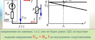
The point is that if we connect a load R, the resistance of which is less than or even equal to r, then the voltage will drop very significantly. This can be seen if you short-circuit the battery terminals with a thick copper wire and measure the voltage at the terminals at this time. But I do not recommend doing this under any circumstances! Therefore, the higher the resistance of the load (that is, the higher the load resistance R), the less influence this load has on the source of electrical energy.
When measuring voltage, a voltmeter and an oscilloscope also slightly drain the voltage of the voltage source being measured, because they are loads with high resistance. This is why the most accurate voltmeter and oscilloscope have a very high resistance between their probes.
Source
Internal resistance of the EMF source
The thing is that a resistance is “hidden” in the battery, which, relatively speaking, clings in series with the source of the battery’s emf. It is called internal resistance or output resistance. Indicated by a small letter “r”.
It all looks like this in the battery:
We hook the light bulb
So, what do we get in its pure form?
A light bulb is a load that has resistance. So, we simplify the diagram even more and get:
We have an ideal EMF source, internal resistance r and load resistance R. Recall the article voltage divider. It says that the voltage of the EMF source is equal to the sum of the voltage drops across each resistance.
The voltage UR drops across the resistor R, and the voltage Ur drops across the internal resistor r.
Now let's remember the article current divider. The current flowing through series-connected resistances is the same everywhere.
Let's remember algebra for 5th grade and write down everything that we just talked about. From Ohm's law for a section of the chain we obtain that
Further
How to write a complaint
The application is written in free form; it is better to do it in printed form to avoid questions about illegible handwriting. Collect the signatures of all concerned, if this is a collective complaint, and take it to the management organization or send it by registered mail. A registered letter is issued to ensure that the addressee has received the application. The mail receipt may later be useful when contacting the prosecutor's office or court.
The application must indicate:
- Name of company.
- Full name of the head of the organization to which the complaint is being sent.
- The applicant’s full name and contact details – address and telephone number.
- Detailed description of the problem.
- Signatures and date of writing.
A finished application for low voltage in the network may look like this: sample.
If the complaint is written electronically on the management company’s website, it is enough to fill out all the proposed fields.
How is internal resistance measured?
To determine the value of the characteristic under consideration, measurements are used during a direct short circuit of the terminals, which is called a short circuit. As you know, if you short-circuit the terminals of a source, a significant current will flow between them. This is often the result of carelessness and leads to burning of the insulation and melting of the wire.
During a short circuit, the circuit resistance becomes minimal. By accurately measuring the current in this situation and knowing the voltage at the terminals when there is no load, you can determine the internal resistance of the power supply. To do this you will need the following formula:
r = U / I(deputy), where
- the letter r denotes the internal resistance of the current source;
- U is the potential difference at the battery terminals without connection to the electrical circuit;
- I(deputy) - the current that passes when the terminals are directly connected to each other.
Finding the load value in this way is not always possible or practical, since a short circuit can cause a serious accident.
Therefore, other solutions to the question of how to find the internal resistance of a source are used. For example, using special measuring instruments. The original iMax B6, ToolkinRC M8, M6, M600 chargers are equipped with the function of measuring this parameter.
Voltage sag
So, meet the car battery!
For further use, solder two wires to it: red to positive, black to negative
Our ward is ready for battle.
Now we take a car halogen light bulb and also solder two wires with alligators to it. I soldered the low beam to the terminals.
First of all, let's measure the voltage at the battery terminals
12.09 volts. This is quite normal, since our battery produces exactly 12 volts. Let me jump ahead a little and say that now we have measured the EMF.
We connect the halogen lamp to the battery and measure the voltage again:
Have you seen it? The voltage at the battery terminals dropped to 11.79 Volts!
Let's measure how much current our lamp consumes in Amperes. To do this, we create the following diagram:
The yellow multimeter will measure voltage, and the red multimeter will measure current. You can read how to measure current and voltage using a multimeter in this article.
Let's look at the instrument readings:
As we can see, our lamp consumes 4.35 Amperes. The voltage dropped to 11.79 Volts.
Let's replace the halogen lamp with a simple 12 Volt incandescent lamp from a motorcycle
The light bulb consumes a current of 0.69 Amps. The voltage dropped to 12 volts exactly.
What conclusions can be drawn? The more current the load consumes, the more the battery voltage drops.
Why do you need to know internal resistance?
At first glance, it may seem that the presence of internal resistance is interesting only from a theoretical point of view. In fact, in some situations, knowing what it equals can be vital.
One such situation is determining the health of a car battery. Its internal resistance is not constant. It changes under the influence of various factors and affects the voltage at the terminals. To be confident in the performance of the equipment, you need not only to be able to find its internal resistance, but also to know what its value corresponds to the norm.
The internal resistance of the power supply can be influenced by the following factors:
- Temperature conditions. The colder it is, the slower the rate of chemical processes in the battery. This leads to an increase in internal resistance and a gradual decrease in voltage at the terminals.
- Battery life. New devices have minimal internal resistance. Gradually it begins to grow. This is due to the fact that an irreversible chemical process occurs in the battery. In some cases it is relatively slow, and in others it can be quite noticeable. The latter, for example, applies to lead-acid batteries.
- Battery capacity.
- Sometimes the device may be subject to mechanical stress, which can cause internal breaks.
- Amount of electrolyte used.
- The current produced by the battery depends on the load on the circuit. Depending on it, the resistance changes.
It will be interesting➡ What is a phototransistor?
The influence of a large number of factors leads to the fact that different values of internal resistance can be considered normal. However, its standard increase per year is considered to be 5%. If this norm is exceeded, it means that you need to pay special attention to the health of the battery.
When analyzing, it is worth taking into account not only those values that are indicated in the technical documentation. It is also necessary to take into account how intensively the resistance changes over time. This will give more accurate information about the health of the battery and help you understand what needs to be achieved to ensure the functionality of the equipment.
One of the simplest ways to measure internal resistance can be demonstrated with the following example. Its use is possible provided that the emf of the battery is known.
EMF (ℰ, unit of measurement - volts, V) is the electromotive force of the power source, equal to the ratio of the work of external forces to move a charge from the negative pole of the source to the positive pole to the value of this charge: ℰ = A/q. If there is no load connected to the power source, then the EMF is equal in value to the voltage at its terminals.
The situation will be considered when the EMF is 1.5 V. An electrical circuit is created in which the battery outputs are connected to a light bulb. The voltage drop across it and the current passing through the circuit are measured. They are respectively equal to 1.2 V and 0.3 A.
The figures given here are approximate. When measuring, the technician can select a different type of electrical load if he deems it necessary.
Using Ohm's law, you can determine the resistance of a light bulb:
R = U / I = 1.2 / 0.3 = 4 ohms.
In this formula, the letter R denotes the total resistance of the circuit. It can be expressed as the sum of r + R, where r is the internal resistance and R is the normal resistance.
Then: R + r = ℰ / I
From this formula, r = ℰ / I − R = 1.5 / 0.3 − 4 = 1 Ohm is determined.
An important condition for finding the value of r is knowledge of the magnitude of the electromotive force. This characteristic has a maximum value for new and well-charged batteries. Those that have been in use for a long time may have a significantly lower EMF due to discharge and wear, which is often associated with irreversible chemical processes in the battery.
To determine ℰ, you must disconnect any load from the power supply terminals and connect a voltmeter or multimeter in voltage measurement mode. The device will show the EMF value. Why is easy to understand. According to Ohm's law for a complete circuit:
I = ℰ / (R + r),
since the voltmeter has a resistance R→∞, then the current I≈0. Therefore, the voltage at the terminals is equal to the emf:
U = I·R = ℰ – I·r = ℰ.
It should also be mentioned that only an ideal voltage generator has zero internal resistance “r”. There are also elements with high internal resistance - these are different sensors, signal sources, and only an ideal current source has r=∞. In addition, there are two-terminal networks with a negative r value; it can be obtained in feedback circuits and in elements with negative differential resistance. The calculations are applicable not only for a battery, but also for any other current source, for example, a galvanic battery, a two-terminal network, a phase-zero loop. This knowledge can be used to match source and load, reduce high voltages and minimize noise.
The total resistance of an electrical circuit, what it is equal to and how to find it using the formula.
Topic: how to find out what resistance an electrical circuit or circuit has using the formula.
As you know, everything needs its own measure, which allows you to make precise systems, devices, mechanisms, circuits. The measure is multiple and has its own specific values. In the field of electrical engineering, the main quantities are voltage, current, resistance, power, frequency (for alternating and pulsed current). The quantities are related to each other by certain formulas
The most important formula, most used by electricians and electronics engineers, is Ohm's law (I = U/R, that is, the current strength is equal to the voltage divided by the resistance). Knowing any two quantities from this formula you can always find the third
The current strength at a certain voltage depends on the resistance of the electrical circuit. If the resistance in the circuit circuits changes, then the modes of its operation change in its individual sections or in the entire circuit. Knowing the resistance value can help identify a malfunction and find out (calculate from the formula) other electrical quantities in the circuit that depend on this resistance.
Now let's look at what the total resistance of an electrical circuit depends on. The general is the sum of the particulars. Any electrical circuit or circuit contains electrical components that have internal resistance. Even an ordinary capacitor (two conductor plates separated by a dielectric, which allows the accumulation of electrical charge between these plates without passing direct current), which, it would seem, inherently should not have it (more precisely, it is infinitely large) has reactance.
The simplest electrical circuit consists of a power source and a load. For example, it will be an ordinary battery and a small incandescent light bulb. Both the battery and the light bulb have their own resistances, which are summed up, which determines the strength of the current flowing through this simplest circuit (at a certain voltage value). Let's say we add another load element to our circuit (a second similar light bulb). It can be connected to this simplest circuit in two ways, either parallel to the first light bulb or in series with it.
When connected in series, the resistance will add up:
When connected in parallel, the total resistance can be found using the following formulas:
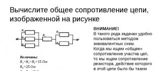
That is, most circuits will have either a parallel connection of resistances, a series connection, or a mixed connection. In the case of a complex electrical circuit, the determination of the total electrical resistance occurs in parts (groups), again consisting of parallel and series connections of elements with resistance. It is more correct to start with that part of the circuit, the circuit, which has the greatest distance from the two final terminals, considered as contacts of common resistance. The figure below shows an example of the sequence of calculating the total resistance of a complex circuit or circuit.
But there are electrical circuits in which the total resistance can constantly change, for example, a circuit of a stabilized speed controller of a permanent electric motor connected to the engine itself. When the load on the motor shaft changes, its internal resistance will change, therefore the operating modes of the circuit (which maintains the desired shaft speed) will also change. In such circuits, the electrical resistance is dynamic and changing. You can only calculate the average resistance, which will not be absolutely accurate.
In addition, as noted earlier, there is also reactance, which occurs in inductive and capacitive circuit elements. It clearly manifests itself in circuits that operate with alternating, pulsed current. If in DC circuits a capacitor (standing in series) does not conduct current through itself, then in an AC circuit everything will be different. Moreover, its reactance will depend on the frequency (for the same capacitance). Here are the formulas for finding reactive capacitive and inductive reactance:
PS the total resistance can also be found through the use of Ohm's law, which states that resistance is equal to voltage divided by current. Therefore, we take a multimeter, measure the current and voltage at the place in the circuit where we want to find out the resistance. Using Ohm's formula, we find (determine) the electrical resistance of the desired section of the circuit. Let me remind you that when using Ohm's law, you need to use the basic units of measurement - current in amperes, voltage in volts, and resistance in ohms.
Calculation of the internal resistance of the voltage source
Real voltage sources have their own electrical resistance, which is called “internal resistance”. The load connected to the source terminals is designated as “external resistance” - R.
A battery of batteries generates EMF:
ε = E/Q, where:
- E – energy (J);
- Q – charge (C).
The total emf of a battery cell is its open circuit voltage when there is no load. It can be checked with good accuracy using a digital multimeter. The potential difference measured at the output terminals of the battery when it is connected to a load resistor will be less than its voltage when the circuit is open, due to the flow of current through the external load and through the internal resistance of the source, this leads to the dissipation of energy in it as thermal radiation .
The internal resistance of a chemical battery is between a fraction of an ohm and a few ohms and is mainly due to the resistance of the electrolytic materials used in the manufacture of the battery.
If a resistor with resistance R is connected to a battery, the current in the circuit is I = ε/(R + r).
Internal resistance is not a constant value. It is affected by the type of battery (alkaline, lead-acid, etc.), and changes depending on the load value, temperature and period of use of the battery. For example, with disposable batteries, the internal resistance increases during use, and the voltage therefore drops until it reaches a state that is unsuitable for further use.
If the emf of the source is a predetermined quantity, the internal resistance of the source is determined by measuring the current flowing through the load resistance.
- Since the internal and external resistance in the approximate circuit are connected in series, you can use Ohm's and Kirchhoff's laws to apply the formula:
- From this expression r = ε/I - R.
Example.
A battery with a known emf ε = 1.5 V is connected in series with a light bulb. The voltage drop across the light bulb is 1.2 V. Therefore, the internal resistance of the element creates a voltage drop: 1.5 - 1.2 = 0.3 V. The resistance of the wires in the circuit is considered negligible, the resistance of the lamp is not known. Measured current passing through the circuit: I = 0.3 A. It is necessary to determine the internal resistance of the battery.
- According to Ohm's law, the resistance of the light bulb is R = U/I = 1.2/0.3 = 4 Ohms;
- Now, according to the formula for calculating the internal resistance, r = ε/I - R = 1.5/0.3 - 4 = 1 Ohm.
In the event of a short circuit, the external resistance drops to almost zero. The current can only be limited by the small resistance of the source. The current generated in such a situation is so strong that the voltage source may be damaged by the thermal effects of the current and there is a risk of fire. The risk of fire is prevented by installing fuses, for example in car battery circuits.
It will be interesting➡ Resonance of tension. Where is the phenomenon of voltage resonance used?
The internal resistance of a voltage source is an important factor when deciding how to deliver the most efficient power to a connected electrical appliance.
Important!
Maximum power transfer occurs when the internal resistance of the source is equal to the resistance of the load.
However, under this condition, remembering the formula P = I² x R, an identical amount of energy is transferred to the load and dissipated in the source itself, and its efficiency is only 50%.
Load requirements must be carefully considered to decide on the best use of the source. For example, a lead-acid car battery must deliver high currents at a relatively low voltage of 12 V. Its low internal resistance allows it to do this.
In some cases, high voltage power supplies must have extremely high internal resistance to limit short-circuit current.
Finding internal resistance
It can be found in two ways: calculated or measured. The first path is taken when working with electrical circuits, the second is chosen when working with real devices.
A simple calculation is made using the Ohm's Law formula for a section of a complete circuit:
To find out the current strength, you need to divide the EMF voltage by the sum of the resistances.
Expressing r from here, we get the formula for calculating it:
Where:
- r – internal resistance of the source;
- ε – source emf;
- I – current strength in the complete circuit;
- R is the resistance in the complete circuit.
The complex of measurements of this parameter for this device does not imply direct measurements. The voltages across the load resistance are tested in two current modes: no-load and short-circuit.
Since not any source can withstand even a short-term short circuit, a measurement method without calculations is taken.
The circuit includes an external load resistance in the form of a trimming resistor Rн. The value is set at which the voltage drop across the resistor would be equal to 1/2 U no-load. Then Rн measured by an ohmmeter will correspond to the internal resistance of the source.
Two-terminal network and its equivalent circuit
A two-terminal network is an electrical circuit containing two points of connection to other circuits. There are two types of electrical circuits:
- circuits containing a source of current or voltage;
- bipolar networks that are not sources.
The first are characterized by electrical parameters: current, voltage and impedance. To calculate the parameters of such two-terminal networks, real circuit elements are first replaced with ideal elements. The combination that results from such a replacement is called an equivalent circuit.
Attention! When working with complex electrical circuits, taking into account the fact that the device operates at the same frequency, it is permissible to convert serial and parallel branches to obtain a simple circuit available for calculating parameters.
The second type of two-terminal circuits can be characterized only by the value of internal resistance.
Table of resistivities of various materials
| Specific resistance ρ, Ohm*mm2/m | Specific resistance ρ, Ohm*mm2/m |
| Aluminum | 0,028 |
| Bronze | 0,095 – 0,1 |
| Bismuth | 1,2 |
| Tungsten | 0,05 |
| Iron | 0,1 |
| Gold | 0,023 |
| Iridium | 0,0474 |
| Constantan (Ni-Cu + Mn alloy) | 0,5 |
| Brass | 0,025 – 0,108 |
| Magnesium | 0,045 |
| Manganin (alloy of copper, manganese and nickel – instrument) | 0,43 – 0,51 |
| Copper | 0,0175 |
| Molybdenum | 0,059 |
| Nickel silver (an alloy of copper, zinc and nickel) | 0,2 |
| Sodium | 0,047 |
| Nickelin (an alloy of copper and nickel) | 0,42 |
| Nickel | 0,087 |
| Nichrome (an alloy of nickel, iron chromium and manganese) | 1,05 – 1,4 |
| Tin | 0,12 |
| Platinum | 0.107 |
| Mercury | 0,94 |
| Lead | 0,22 |
| Silver | 0,015 |
| Steel | 0,103 – 0,137 |
| Titanium | 0,6 |
| Hromal | 1,3 – 1,5 |
| Zinc | 0,054 |
| Cast iron | 0,5-1,0 |
Answer: The filament is made of constantan.
When "resistance is futile"
Electric current is a smart and cunning guy. If it has the ability to bypass the resistor and follow a perfect conductor without resistance, it will do so. At the same time, this will not work with resistors of simply different values: it will not simply go through less resistance, but will be distributed according to Ohm’s law - more current will go where the resistance is less, and vice versa.
But in the figure below, the circuit resistance is zero, because no current will flow through the resistor.
Current follows the path of least resistance.
Now let's look at Ohm's law for a section of the circuit again.
| Ohm's law for a circuit section I = U/R I - current strength [A] U - voltage [V] R - resistance [Ohm] |
Let's substitute a resistance equal to 0. It turns out that the denominator is equal to zero, but in mathematics they say that you cannot divide by zero. But we will reveal a terrible secret to you, just don’t tell the mathematicians: you can divide by zero. If we completely simplify such a complex calculation (precisely because it is complex, we always say that it cannot be done), then we get infinity.
That is:
I = U/0 = ∞
This case is called a short circuit - when the magnitude of the current is so great that it can be directed to infinity. In such situations we see a spark, a storm, madness - and everything breaks.
This happens because two points in the circuit have a voltage between them (that is, there is a difference between them). It's like a waterfall suddenly appearing along a river. This difference causes a spark, which can be avoided by placing a resistor in the circuit.
It is in order to avoid short circuits that additional resistance is needed in the circuit.
Measuring internal resistance.
There are several methods for measuring internal resistance. Two of them are specified in GOST R IEC 61960-2007. Before measuring using any of the methods below, the battery must be fully charged. Tests are carried out at a temperature of 20±5ºC.
Measuring internal resistance using the AC method (a.c.)
This method measures impedance, which at 1000 Hz is approximately equal to resistance.
Electrical impedance (complex electrical resistance) (English impedance from Latin impedio “to hinder”) is the complex resistance between two nodes of a circuit or two-terminal network for a harmonic signal.
Description of the methodology from GOST
For one to five seconds, we measure the root-mean-square value of the alternating voltage Urms, which occurs when an alternating current with a root-mean-square value Irms passes through the battery, following with a frequency of 1000 Hz. Internal resistance Ra.c., Ohm is calculated using the formula Ra.c.= Urms / Irms.
Irms (rms – Root Mean Square – root mean square value).
The alternating current must be of such a value that the peak voltage does not exceed 20 mV.
This method is difficult to implement at home without special equipment. The popular YR1035 device does an excellent job of measuring with an accuracy of 0.01 mOhm. Chargers SKYRC MC3000, Opus BT-C3100V2.2, Liitokala Lii-500 are also measured using the AC method, but with very mediocre accuracy.
Measuring internal resistance using the direct current (dc) method
This method can be performed at home using a regular voltmeter and ammeter and a pair of suitable load resistors. As resistances, it is quite possible to use several car incandescent lamps or an improvised resistor made of nichrome wire.
Description of the method from GOST
- We discharge the battery with direct current I1= 0.2 In. At the tenth second we measure the voltage value U1 at the battery terminals.
- We increase the discharge current to the value I2=In. In the next second, we measure the value of voltage U2 at the battery terminals.
Internal resistance Rd.c., Ohm is calculated using the formula Rd.c. = (U1-U2)/(I2-I1)
- Iн – rated battery discharge current.
Circuit for measuring internal resistance using the direct current (dc) technique
The resistances R1 and R2 are selected in such a way that currents I1 and I2 of the required magnitude flow. You need to focus on the rated discharge current of the battery.
The voltmeter must be connected directly to the source poles to eliminate the influence of voltage drop on the wires.
Ideal current source
The ideal current source is an active element whose current does not depend on the voltage at its terminals. It is assumed that the internal resistance of an ideal current source is infinitely large, and therefore the parameters of the external electrical circuit, on which the voltage at the source terminals depends, do not affect the source current. The symbols of an ideal current source are shown in Fig. 1
The arrow in the current source or the signs “+” and “—” indicate the positive direction of the current i(t)
or the polarity of the source, i.e. the direction of movement of positive charges.
Nowadays it is customary to denote current sources with the letter J, and the lower conventional graphic image is most often used.
Ideal current source
As the resistance of an external electrical circuit connected to an ideal
At a current source, the voltage at its terminals and, accordingly, the power developed by it increase indefinitely. Therefore, an ideal current source, as well as an ideal voltage source, is considered as a source of infinite power.
A current source of finite power is depicted as an ideal current source with a passive element connected in parallel to its terminals, which characterizes the internal parameters of the source and
Representing a theoretical concept, a current source is used in a number of cases to calculate electrical circuits.
Some semblance of a current source can be a device consisting of a battery connected in series with an additional high resistance. Another example of a current source can be a five-electrode amplifying electron tube (pentode). Having an internal resistance incommensurably greater than the resistance of the external electrical circuit, these devices deliver a current that is almost independent of changes in the external load over a wide range, and it is in this respect that they are similar to a current source.
Source discharge capacity
The value depending on the strength of the discharge current is called the discharge capacity of the source. This is an electric charge that the source gives off during operation depending on the load current. This value can be considered constant conditionally. Thus, a starter battery with a discharge capacity C = 55 A*h will work for 10 hours at a discharge current of 5.5 A. When starting a cold or malfunctioning vehicle, the battery can be discharged in a few minutes.
In order to find the residual discharge capacity, charge-discharge cycles are performed. They are performed using load resistors. The discharge to the load resistance is carried out to the minimum permissible values of the electrolyte density. In this case, the operating time under load is measured. This is relevant during seasonal maintenance of batteries to identify self-discharge processes.
Car battery discharge capacity
The internal resistance of current sources is an important quantity. The methods used to reduce it are direct ways to increase the output power of the source, which means increasing the productivity of two-terminal networks. Correct measurement and calculation of the impedance of equivalent circuits allows us to bring the two-terminal network closer to the ideal source.
How to use a multimeter correctly: instructions for dummies
Let's look at how to measure several electrical characteristics.
Potential
Algorithm for determining voltage:
- Set the mode to ACV or DCV position in the expected interval.
- Connect the black wire to the COM connector, the red wire to the VΩmA connector.
- Connect the tips of the probes to the circuit contacts. For example, insert batteries into the holes of a socket or onto the poles.
- Take a measurement.
The number displayed on the display is the voltage value in volts. The minus sign indicates that the polarity has been reversed. If the multimeter supports the hold function, the value can be locked using the HOLD button. This is convenient for a large chain of measurements.
Current strength
This characteristic is measured only when the tester is connected in series to the circuit and the power is turned on. Most devices make it possible to determine current strength up to 10 A, since large values are rarely used in everyday life. To carry out measurements, a break is made in the circuit. Further actions according to the following scheme:
- The black probe goes into the COM socket.
- Red - into the connector up to 200 mA or 10A.
- Use the tips to gently touch the contacts.
- Read the voltage value from the display.
When working with exposed wires, you must follow safety precautions to prevent electric shock.
Resistance
This characteristic can be measured without power supply. The element being tested is simply closed between two probes. If there is no conductivity, a unit is displayed on the screen. Sequencing:
- Set Ω mode by selecting maximum range.
- Insert the probes into the appropriate connectors.
- Check the condition - short the probes to each other. A 0 or small number should appear, which must be taken into account when measuring the resistance of the circuit.
- Throw the ends of the conductors onto the contacts of the object under study.
- The resistance of the element or section of the circuit will appear on the screen.
For accurate measurements, 2-3 attempts are recommended.