Electricity
Electric current flows through the wires.
Moreover, it “flows”, almost like water. Let's imagine that you are a happy farmer who decided to water his garden with a hose. You opened the tap slightly, and water immediately ran through the hose. Slowly, but still she ran. The jet force is very weak. Then you decided that more pressure was needed and opened the tap to its fullest. As a result, the stream will flow with such force that not a single tomato will be left unattended, although in both cases the diameter of the hose is the same.
Now imagine that you are filling two buckets from two hoses. Green has stronger pressure, yellow has weaker pressure. The bucket into which water is poured from a hose with strong pressure will fill faster. The thing is that the volume of water for an equal period of time from two different hoses is also different. In other words, a much larger number of water molecules will run out of the green hose than from the yellow hose in the same period of time.
If we take a conductor with current, the same thing will happen: charged particles will move along the conductor, just like water molecules. If more charged particles move along the conductor, the “pressure” will also increase.
- Electric current is the directed movement of charged particles.
What is voltage and current?
By the way, what exactly are electric current and voltage? I think that no one really knows, because to know it you have to at least see it. Who can see the current running through the wires?
Yes, no one, humanity has not yet achieved such technologies to personally observe the movements of electric charges. All that we see in textbooks and scientific works is some kind of abstraction created as a result of numerous observations.
Well, okay, we can talk a lot about this... So let's try to figure out what electric current and voltage are. I will not write definitions; definitions do not give the very understanding of the essence. If interested, take any physics textbook.
Since we do not see the electric current and all the processes occurring in the conductor, then we will try to create an analogy.
And traditionally, the electric current flowing in a conductor is compared to water running through pipes. In our analogy, water is an electric current. Water runs through the pipes at a certain speed, the speed is the current strength, measured in amperes. Well, pipes are a conductor in themselves.
Okay, we imagined electric current, but what is voltage? Let's help now.
The water in the pipe, in the absence of any forces (gravity, pressure), will not flow; it will rest like any other liquid poured onto the floor. So this force, or more precisely, energy in our plumbing analogy, will be the same tension.
But what happens to the water running from a reservoir located high above the ground? Water rushes in a stormy stream from the reservoir to the surface of the earth, driven by gravitational forces. And the higher the reservoir is located from the ground, the faster the water flows out of the hose. Do you understand what I'm talking about?
The higher the tank, the greater the force (read voltage) acting on the water. And the greater the speed of the water flow (read current strength). Now it becomes clear and a colorful picture begins to form in my head.
Current strength
There immediately arises a need for a quantity with which we will measure the “pressure” of the electric current. Such that it depends on the number of particles that flow through the conductor.
Current strength is a physical quantity that shows how much charge has passed through a conductor per unit time.
How is current strength indicated?
The current strength is indicated by the letter I
| Current strength I = q/t I - current strength [A] q - charge [C] t — time [s] |
Current strength is measured in amperes. The unit of measurement was chosen for a reason.
Firstly, it is named after the physicist André-Marie Ampère, who studied electrical phenomena. And secondly, the unit of this quantity was chosen based on the phenomenon of interaction of two conductors.
Here, unfortunately, it is impossible to draw an analogy with a water supply system. Hoses with water do not attract or repel each other close to each other (which is a pity, it would be funny).
When current flows through two parallel conductors in the same direction, the conductors attract each other. And when in the opposite direction (along the same conductors) they repel.
The unit of current 1 A is taken to be the current at which two parallel conductors 1 m long, located at a distance of 1 m from each other in a vacuum, interact with a force of 0.0000002 N.
Task
Find the current strength in the circuit if a charge equal to 300 mC passes through it in 2 seconds.
Solution:
Let's take the formula for current strength
I = q/t
Let's substitute the values
I = 300 mC / 2 s = 150 mA
Answer: the current in the circuit is 150 mA
To remember the theory well, you need a lot of practice. The classic physics course for grade 10 at the Skysmart online school is an excellent opportunity to practice solving problems.
Current in semiconductors and its characteristics
The electrical properties of semiconductors strongly depend on external conditions: temperature, light irradiation. To increase their own conductivity, special impurities are added to the structure.
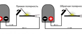
Therefore, inside the semiconductor, the current is created due to the intrinsic and impurity conductivity of the internal pn junction. The charge carriers of a semiconductor are electrons and holes. If the positive potential of the voltage source is applied to pole p, and the negative potential to pole n, then current will flow through the pn junction due to the movement they create.
When the polarity is applied in reverse, the pn junction remains closed. Therefore, in the picture above, in the first case, a light bulb is shown, and in the second, an extinguished one.
Similar pn junctions work in other semiconductor designs: transistors, zener diodes, thyristors...
All of them are designed to carry rated current. To do this, markings are applied directly to their body. Using it, they enter the tables of technical reference books and evaluate the semiconductor based on its electrical characteristics.
Conductors and dielectrics
Some divide the world into black and white, while we divide it into conductors and dielectrics.
- Conductors are materials that conduct electric current. The best conductors are metals.
- Dielectrics are materials that do not conduct electric current. Easy!
| Conductors | Dielectrics |
| Copper, iron, aluminum, tin, lead, gold, silver, chromium, nickel, tungsten | Air, distilled water, polyvinyl chloride, amber, glass, rubber, polyethylene, polypropylene, polyamide, dry wood, rubber |
Just because a dielectric doesn't conduct electricity doesn't mean it can't store charge. The accumulation of charge does not depend on the ability to transfer it.
Through charge and time
electricity is the amount of charge driven by the forces of an electric field that overcomes the conventional plane of a conductor, called the cross-section of the conductor, per unit time.
Definition of current strength
Thus, if the electric charge passed through a conductor in a certain time is known, then it is not difficult to find the value of this charge passed per unit time, that is: I = q/t
Current direction
Previously, in physics textbooks they wrote this: once upon a time they decided that the current was directed from plus to minus, and then they found out that electrons flow through the wires. But these electrons are negative, which means they cannot go to minus. But since we’ve already agreed on the direction, let’s leave it as it is. The question then arose for everyone: why can’t the direction of the current be changed? But no one received an answer.
Now they write it a little differently: positive particles flow along the conductor from plus to minus, and the current is directed there. No one has any questions here.
| So which version is correct? Actually, both. The charge carriers in each type of material are different. In metals these are electrons, in electrolytes they are ions. Each type of particle has its own signs and need to run to the oppositely charged pole of the current source. We will not choose the direction of current for each type of material in order to solve the problem! Therefore, it is customary to direct the current from plus to minus. In most school course problems, the direction of the current does not play a role, but there is that insidious minority where this point will be very important. Therefore, remember - we direct the current from plus to minus . |
How to measure direct current with a multimeter
Batteries and accumulators are most often checked; they are constant sources.
In how to measure amperes with a multimeter, it is important to select the appropriate function on the device, as well as connect the tester in the correct polarity: red cable to positive power, black to negative. If the probes are mixed up, the display will show negative numbers.
Also, regarding how to measure current with a multimeter, you need to understand what signal level will be tested. If the circuit contains milliamps, the red cable is connected to the hole on the multimeter where VΩmA is indicated or a certain range is written. If you are examining a power circuit where the Amps are, connect to the one labeled A or NA (usually 5-10 A here). Again, we advise you to carefully study the instructions for the multimeter. If you mess something up at this stage, the multimeter may break.
Instructions for measuring DC current with a multimeter:
- We arrange the probes.
- Select the DC function.
- If necessary, set the signal level (set it higher than what you expect).
- We connect the tester into a break in the chain of the circuit branch, not forgetting to observe the polarity.
- Turn on the energy source.
If there are no values, the range is most likely selected incorrectly. Try lowering it until you see a reading.
See how to measure amperes with a multimeter:
How to measure amperage with a battery-powered multimeter
It is a simple portable power source and does not require the application of a load. Apart from this, the remaining steps are the same: select the desired function on the multimeter, arrange the probes in accordance with the polarity.
What the readings may indicate:
- 4-6 A - everything is fine.
- Below four - the battery is only suitable for use in low-power devices.
- Below 2.5 A - this battery is asking for trash.
Compare the readings with those written on the batteries.
Watch a useful video on how to measure battery amperes with a multimeter:
How to check the current of a battery with a multimeter
The rule here is with a load element, which can be a simple incandescent light bulb. Most likely, its resistance will be no more than several hundred Ohms. How to check the load with a multimeter? Tester, selecting the desired mode. For example, read more about checking resistance with a multimeter here.
Then use this formula: I = U / R (I - current A, U - battery voltage, R - light bulb resistance).
Compare the numbers you get when measuring the current with a multimeter with the resulting value. If you see a difference, especially a significant one, it may be a bad charge.
Useful video on how to check amperes with a multimeter:
Current source
The water in the hose comes from a water supply, a spring with water in the ground - in general, not from nowhere. Electric current also has its own source.
The source can be, for example, a galvanic cell (a conventional battery). A battery works based on chemical reactions inside it. These reactions release energy, which is then transferred to the electrical circuit.
Any source necessarily has poles - “plus” and “minus”. The poles are its extreme positions. Essentially the terminals to which an electrical circuit is connected. Actually, the current flows from “+” to “-”.
Ohm's Law Triangle Method
Ohm's Law is a very simple and useful tool for analyzing electrical circuits. It is used so often in the study of electricity and electronics that the student must memorize it. If you are not very good at working with formulas, then for memorizing it there is a simple trick that helps you use it for any quantity, knowing the other two. First, arrange the letters E, I and R in a triangle like this:
Figure 5 – Ohm's law triangle
If you know E and I and want to define R, just remove R from the picture and see what's left:
Figure 6 - Ohm's law for determining R
If you know E and R and want to define I, remove I and see what's left:
Figure 7 - Ohm's law for determining I
Finally, if you know I and R and want to define E, remove E and see what's left:
Figure 8 - Ohm's law for determining E
Ultimately, you'll have to learn how to work with formulas to study electricity and electronics seriously, but this tip can make it easier to remember your first calculations. If you're comfortable working with formulas, all you have to do is commit E = IR to memory and retrieve the other two formulas when you need them!
Ammeter
We know where the current is directed, how the current is measured, how to calculate it, knowing the charge and the time during which this charge has passed. All that remains is to measure.
A device for measuring current is called ammeter . It is included in an electrical circuit in series with the conductor in which the current is measured .
Ammeters come in very different operating principles: electromagnetic, magnetoelectric, electrodynamic, thermal and induction - and these are just the most common.
We will only consider the principle of operation of a thermal ammeter, because to understand the principle of operation of other devices it is necessary to know what a magnetic field and coils are.
The thermal ammeter is based on the property of current to heat wires. It is designed like this: a thin wire is attached to two fixed clamps. This thin wire is pulled down by a silk thread connected to a spring. Along the way, this thread loops around the fixed axis on which the arrow is attached. The measured current is supplied to the fixed clamps and passes through the wire (arrows in the figure show the current path).
Under the influence of current, the wire will heat up slightly, causing it to elongate, as a result of which the silk thread attached to the wire will be pulled back by a spring. The movement of the thread will turn the axis, and therefore the arrow. The arrow will indicate the measurement value.
Nonlinear elements and circuits
Ohm's law is not a fundamental law of nature and can be applied in limited cases, for example, for most conductors. It cannot be used to calculate voltage and current in semiconductor or vacuum devices, where this dependence is not proportional and can only be determined using the current-voltage characteristic (volt-ampere characteristic).
This category of elements includes all semiconductor devices (diodes, transistors, zener diodes, thyristors, varicaps, etc.) and vacuum tubes. Such elements and the circuits in which they are used are called nonlinear.
How the law works in real life
Using the power calculation formula and Ohm's law together, you can make calculations without knowing one of the quantities. The simplest example is that for an incandescent lamp only its power and voltage are known. Using the above formulas, you can easily determine the parameters of the filament and the current through it.
Incandescent lamp
Current formula through power:
I=P/U;
Resistance:
R=U/I.
The same result can be found from the power without resorting to intermediate calculations:
R=U2/P.
Similarly, you can calculate any quantity knowing only two of them. To simplify transformations, there is a mnemonic display of formulas that allows you to find any quantities.
Rule for remembering calculations
Looking carefully at the formulas, you can see that if you reduce the voltage on the lamp by half, the expected power will not decrease by the same factor by half, but by four, according to the formula:
P=U2/R.
This is a fairly common mistake among people who are far from electrical engineering, who incorrectly correlate power and voltage, as well as their effect on other parameters.
By the way. The current found through resistance and voltage is valid for both direct and alternating current, as long as it does not use elements such as a capacitor or inductance.
You can make calculations easier by using an online calculator.
Measuring instruments
Measuring instruments are used to measure the parameters of electrical circuits:
- Voltmeter;
- Ammeter;
- Ohmmeter.
The most commonly used class of combined devices in which the measured value is selected by a switch is ampere-volt-ohmmeters or avometers.
One of the most common avometers
Example with ordinary water
There are substances that can be classified as both conductors and insulators. The simplest example is ordinary water. Distilled water is a good insulator, but the presence of almost any impurities in it makes it a conductor. This especially applies to salts of various metals. When dissolved in water, salts dissociate into ions, their presence is a direct reason for the occurrence of current. The higher the concentration of salts, the less resistance the water will have.
Dependence of water resistance on salt content
For clarity, you can take distilled water to prepare electrolyte for car batteries. By lowering the ohmmeter probes into water, you can see that its readings are high. The addition of just a few crystals of table salt after a while causes a sharp decrease in resistance, which will be smaller the more salt goes into solution.
Parallel and serial connection
In electrics, elements are connected either in series - one after the other, or in parallel - this is when several inputs are connected to one point, and outputs from the same elements are connected to another.
Ohm's law for parallel and series connections
Parallel connection
A parallel connection is when the beginnings of the conductors/elements converge at one point, and their ends are connected at another. We will try to explain the laws that are valid for compounds of this type. Let's start with the current. A current of some magnitude is supplied to the point of connection of the elements. It separates, flowing through all conductors. From here we conclude that the total current in the section is equal to the sum of the current on each of the elements: I = I1 + I2 + I3.
Now regarding the voltage. If voltage is the work done to move a charge, then the work required to move one charge will be the same on any element. That is, the voltage on each parallel-connected element will be the same. U = U1=U2=U3. It’s not as fun and visual as in the case of explaining Ohm’s law for a section of a circuit, but you can understand it.
For resistance, everything is a little more complicated. Let's introduce the concept of conductivity. This is a characteristic that shows how easy or difficult it is for a charge to pass through this conductor. It is clear that the lower the resistance, the easier it will be for current to pass. Therefore, conductivity - G - is calculated as the reciprocal of resistance. In the formula it looks like this: G = 1/R.
Laws for parallel connection
Why did we talk about conductivity? Because the total conductivity of a section with a parallel connection of elements is equal to the sum of the conductivity for each of the sections. G = G1 + G2 + G3 - easy to understand. How easy it is for current to cross this node of parallel elements depends on the conductivity of each element. So it turns out that they need to be folded.
Now we can move on to resistance. Since conductivity is the reciprocal of resistance, we can obtain the following formula: 1/R = 1/R1 + 1/R2 + 1/R3.