Three-phase 380V distribution boards are often used in private houses and much less often in apartments in new buildings. This allows you to reduce the cross-section of the cable approaching the house and correctly distribute the load. Often the allocated power per house is 15 kW. This is a very widespread practice in our country. With such allocated power, it is necessary to install an input circuit breaker with a rating of 25A. Also, 3-phase power supply allows you to connect electric stoves using a three-phase circuit. This allows you to reduce the rating of the machine, reduce the cable cross-section and reduce the current consumption per phase. For example, a hob with a power of 7 kW with a single-phase connection will consume a current of 31A, and with a 3-phase connection it will consume about 10A for each phase. Let's look below at typical and non-typical three-phase circuits with clear examples of real assembled electrical panels.
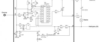
Three-phase distribution board diagram
A typical three-phase switchboard circuit consists of an input 3-phase circuit breaker and several group circuit breakers that protect only their outgoing single-phase lines. Here at the input there is a 3-pole circuit breaker with a rating of 25A-40A and with a characteristic higher than group single-phase circuit breakers (with characteristic C). This is necessary to try to maintain selectivity and avoid simultaneous operation of the input machine and the group one. Although in the event of a short circuit, both the input circuit breaker C25 and the group circuit breaker B16 will most likely work. With such a minimal difference in the ratings of circuit breakers, it is practically impossible to achieve selectivity.
In the circuit, we connect all neutral conductors to a common zero bus, all grounding conductors connect to a common ground bus, and phase conductors connect to circuit breakers. You can combine group circuit breakers by phase using wire jumpers, or better yet, using a special comb bus. Below is a typical three-phase 380V distribution board diagram. Maybe it will be useful for someone, I also inserted an electricity meter here. The TN-S grounding system is presented here. If you have a TN-C grounding system, then you definitely need to switch to a TN-CS grounding system, i.e. divide the incoming PEN conductor into independent zero working N and zero protective PE conductors. Read how to organize this correctly here.
Here is a clear example of connecting circuit breakers in a 3-phase electrical panel. You can see all photos of the assembly of this panel here: Assembly of three-phase electrical panels to order
If someone in the house, in addition to single-phase consumers, has a three-phase load, for example, an electric stove, then the following diagram of a three-phase distribution board should be useful to you. In the presented version, you can connect one 3-phase device and several single-phase ones.
If there is no place in the panel for an electricity meter or it is located in a different place, then here is a 380V panel diagram similar to the previous one, but without a meter. Here all phase conductors go directly to group circuit breakers.
If everything is clear with the previous three-phase distribution board diagrams, then we move on. Below I have posted a diagram for you, where there is also an RCD and a difavtomat. With their help, it is imperative to protect all groups of outlets. This is required by the PUE, and electrical safety should come first. Here the automatic device is only used for a washing machine, since if it is triggered, it will not be so difficult to find a fault. An RCD paired with a circuit breaker is installed on a group of kitchen sockets. You can find out why in pairs here. This is done to make troubleshooting easier, since many different electrical appliances will be included. If the machine works, it means there is a short circuit somewhere, or if you plugged in all the electrical appliances at the same time, then there is most likely an overload. If the RCD has tripped, then most likely there is a leak in some household appliance. Below is shown how to correctly connect an RCD and connect a difavtomat in a 380V panel.
Below is a real example of a three-phase switchboard with the connection of 2-pole and 4-pole RCDs.
Here's another diagram that might be useful to someone. It is built on one common (input) and several group RCDs.
Below are three-phase switchboards completely ready for installation. This is my job building custom electrical panels. This service is available to everyone from anywhere in our vast homeland. Any questions regarding this issue, please write to This email address is being protected from spambots. You must have JavaScript enabled to view it.
I am ready to offer you the purchase of components from official suppliers of electrical materials at a personal discount of up to 20% of the retail price of the ETM. When ordering the assembly of an electrical panel, the development of a circuit diagram and a passport are provided free of charge. I will be very glad to see your orders. From each electrical panel collected, 50% of the income goes to pay off the mortgage. Let's make housing affordable for an electrician together)))
Read also: Michael Faraday and James Maxwell discoveries
You will also be pleased with the colored stickers)))
Still have questions? I will be glad to answer them in the comments. If after this nothing is clear, then do not tempt fate and call a competent electrician.
An electrician, a chemist, a mechanic and a programmer are traveling together in a car. Suddenly the engine stalled. “The electrician says, “The battery is probably dead.” “The chemist says, “No, most likely it’s the wrong gasoline.” – Mechanic, “I think this transmission is not working.” - Programmer, - “Can we get out of the car and go back in?”
When starting to build a house, you should immediately think about the question of what voltage will be used and how many phases to supply to the building. The number of devices that consumers use nowadays significantly increases the load on the lines. This must be taken into account when calculating the total load in order to make the right choice.
Advantages and disadvantages of a three-phase power supply system
To supply electricity to a private home, three-phase power is most often used, since it is superior to single-phase.
Such nutrition can allow:
- use of three-phase motors and other electrical receivers;
- when using a large number of electrical appliances, it is possible to distribute them into three phases, thus reducing the load on each phase;
- allows the use of input cables with a smaller cross-section;
- as a result of a break in one of the phases, the presence of light in the house will still be ensured;
- the risk of fires is significantly reduced.
And yet, along with these positive aspects, there are also a number of negative aspects:
- with a three-phase supply of electricity, the dimensions of the electrical panel will be increased several times. This is due to the size of the meter and the residual current device;
- a voltage of 380 volts can kill a person fatally , while 220V is the maximum permissible safe voltage;
- installation work related to wiring will be much more difficult;
- special attention should be paid to the wiring of the common zero, since if it breaks, an overvoltage will form in the phases, which will inevitably lead to the failure of all devices in this phase;
- the wiring diagram contains many more lines, thus increasing the required number of machines.
Areas of use
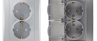
Power sockets are not used in multi-apartment buildings. However, they can be found in individual houses where a three-phase electric stove or electric motor is connected. Photos of 380 Volt sockets will introduce you to these devices.
Also, 380-volt sockets are installed at production and construction sites. Garages and summer cottages are no exception, where there is a need for a welding machine, machine, electric motors and other devices that operate on a three-phase power supply.
Registration of permission
At the first stages, the following will need to be agreed upon with power engineers:
- permissible power;
- number of phases;
- type of input line and energy meter;
- metering tariff (depending on the meter);
- Based on the quality of the insulation of the house electrical network, a connection diagram is agreed upon (if the wiring is old, then permission will not be given);
- How reliable is the grounding of the electrical wiring in the house?
Important! Independent connection to power lines is prohibited by law. The electrical connection must be made by highly qualified specialists.
Next, measurements are made from a private house to 380V networks; if this distance exceeds 300 meters in the city or 500 meters outside the city, then you will have to pay for the installation of an additional support pole.
The next step will be to discuss the required power:
- no more than 16 kW;
- from 16 to 50 kW;
- from 50 to 160 kW.
Typically, up to 50 kW is allowed; if a larger figure is needed, an additional transformer will be required, which is very expensive and difficult.
Further list of required documents:
- a copy of your passport (required to draw up an agreement for connecting electricity);
- application for connection to electrical lines;
- identification code;
- site plan;
- a plan for the placement of the power line pole closest to the site;
- title document for a residential (non-residential) property;
- approved complete residential plan;
- information about the required power and a list of all electrical appliances used in the house (or the estimated number of devices if the house has not yet been put into operation).
The application for electrical wiring to the house should be written in two copies, in order to keep one (with the visa of the specialist accepting the document).
What to look for when purchasing
If you need to choose a three-phase outlet, you should pay attention to the following points:
The current strength for which it is designed. Most often you have to choose between 16, 32 or 64 amp models, depending on the device to which they will be connected. Level of protection against moisture and dust. To check, you need to look for the “IP” marking in the characteristics - the higher the number, the more reliable the protection
In practice, you need to pay attention to this only if the outlet is installed in a place with very high humidity. Do you need a stationary socket or a mobile one? To put it simply, they will hang it on the wall or make a carrier out of it. Number of contacts - selected depending on the use of a specific connection scheme. If you purchase sockets with self-clamping screwless contacts, then you need to make sure that they are working properly - so that they are not disposable.
Design tricks, shape and relative position of contacts - all these details depend on the specific manufacturer and may differ slightly in different device models. They only affect the convenience of finding a new outlet if it needs to be replaced.
Several rules when connecting 380 volts in a private home
Outdated power lines are gradually being modernized and transferred to the new TN-CS model. With this method, the fourth PEN wire is laid from the supply substation not with one wire, but with two disconnected wires: PE and N.
Input of three-phase voltage into the building
To connect 380 volts to a private house, you must follow some rules:
- voltage is transmitted from the transformer substation via power lines (four wires), which include three phase conductors (L1, L2, L3) and one common neutral wire PEN;
- Most often such a line is overhead and less often cable.
A three-phase connection is based on the connection of all conductors to the input apparatus of the object. Next, the current enters the metering device and passes into the distribution panel, for the purpose of subsequent distribution to electrical receivers.
In the middle of the input device, the working zero N and the protective zero PE are separated. Then they are connected to the main ground bus (GZSh). Then it is connected to the repeated grounding circuit of the room.
Read also: Thickness of saw blade for wood
The last section of the line from the support to the entrance to the house is carried out by air or underground. It is also called a branch. It is listed on the balance sheet of the power supply organization, so the connection of the house is made with the permission of the owner of the power line.
If the cable line runs underground, then the branch is mounted in a metal cabinet, which will be located near the route, and for overhead power lines - directly on the support. In both cases, the owner is obliged to ensure their safe operation and prevent unauthorized people from invading the electrical panel.
Important! Carrying out work on the end of the PEN conductor located on the support by residents of the house is prohibited by the rules.
Outgoing lines
With three-phase power supply, an input distribution board (IDB) is installed on the facade of the house. It is in it that the PEN conductor is separated and the input circuit breaker is installed, as well as circuit breakers for the group circuits of the house.
All three phases L1, L2, L3 are connected to a three-pole input circuit breaker (3). An electricity meter is also installed there in order to keep track of the resource consumed. Three conductors from the input machine and conductor N from the main generator are connected to the input terminals of the metering meter. The electricity meter output is connected to a common circuit breaker (four-pole) for protecting the entire house. If it goes off, the entire house will be cut off from power.
The operating voltage between phases is 380 V, and between phases and zero 220 V. After all, this voltage represents three phases in three different wires, only with different instantaneous potentials and a frequency of 50 Hz.
Electrical wiring in the house should be divided into groups, each lighting line is protected by a single-pole circuit breaker (5). Each group is powered from different phases.
In rooms with high humidity levels, you need to use a difavtomat (6), which is triggered when the current reaches no more than 30 milliamps.
For a kitchen group, it is advisable to install a three-pole circuit breaker (9) and a four-pole circuit breaker (10). This is due to the fact that the kitchen power supply is three-phase, so if a phase is short-circuited to zero, it will be necessary to cut off the zero worker and all phase conductors at the same time.
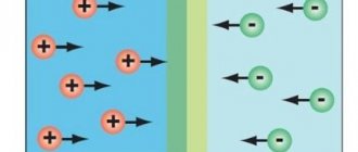
How are three phases different from one?
In both types of power there is a working neutral conductor (ZERO). I talked in detail about protective grounding here; it is a broad topic. In relation to zero in all three phases - the voltage is 220 Volts. But in relation to these three phases to each other, they have 380 Volts.
This happens because the voltages (with active load, and current) on the three phase wires differ by a third of the cycle, i.e. at 120°.
You can read more in the electrical engineering textbook - about voltage and current in a three-phase network, and also see vector diagrams.
It turns out that if we have three-phase voltage, then we have three phase voltages of 220 V each. And single-phase consumers (and there are almost 100% of them in our homes) can be connected to any phase and zero. You just need to do this in such a way that the consumption in each phase is approximately the same, otherwise phase imbalance is possible.
Read more about phase imbalance and what causes it - here.
And it is best to protect yourself from phase imbalance using a voltage relay, for example Barrier or FiF EuroAutomatika.
In addition, it will be difficult for the overly loaded phase and it will be offensive that others are “resting”)
What kind of lighting do you prefer?
Built-in Chandelier
Installation cost
Installing electrical wiring is an important issue. A correctly drawn up house wiring plan is a guarantee of safety. If a person has never encountered such a problem in his practice, then it is better to seek help from trusted specialists.
To do this, you should familiarize yourself with the approximate prices for this type of service:
Initially, you should be prepared for the fact that installing electrical wiring in a house will cost much more than in an apartment.
What kind of sockets are there?
There are several types of 380 volt outlets available in post-Soviet markets. There are both domestic manufacturers and foreign analogues, which are much more expensive.
When purchasing a product, make sure that the electrical appliance fits into the outlet. It is best to take it along with the plug, and then simply replace it with a suitable one.
Electrician's recommendations
You should adhere to the basic rules when working:
- horizontal transitions from the junction box to the sockets or switch are laid at a height of 2.5 m;
- the insertion of veins is carried out only vertically or horizontally;
- connection points should only be located in mounting boxes;
- for underground cable laying, you need to use only a single piece with a strong armor tape;
- The biggest mistake is installing the switch in the zero gap;
- It is forbidden to install electrical wires near a wooden surface, but if this is unavoidable, then an insulating hose or gasket made of asbestos and steel with a thickness of 0.2 - 0.5 mm is used.
Connecting 380V sockets
Having understood the main types and features, you can consider connecting a 380 V outlet. We will do this separately for each type.
Connecting 2P+PE and 3P+PE sockets
Let's start with the simplest connection of a 2P+PE socket. As the name suggests, for this we need two phase wires and one ground wire.
Socket 2P+PE
Based on this, before making the connection, we need to determine the wire data. To do this, we need to decide on the distribution board in which the connection will be made, as well as on the circuit breaker of the appropriate power.
Two-pole machine
- If you will make all the connections yourself, then first of all we run a cable or wire from the distribution board to the outlet. In this case, a three-core cable of the appropriate cross-section will suit us.
- Now we make the connection in the distribution board. First we connect the protective ground wire. To comply with PUE standards and facilitate the connection of the socket, it is advisable to use a yellow-green conductor. We connect it to the PE bus, which should go in the distribution board in addition to any automatic machines.
Connecting PE and N buses in the switchboard
- After this, we connect the phase conductors. They are connected to the terminals of the machine. Before connecting, make sure the machine is turned off.
- Now we connect directly to the outlet. First of all, we again connect the protective ground wire. Above, we have already decided on its labeling.
3P+PE socket connection diagram
The circuit diagram of a 380V socket of the 3P+PE type is almost identical to the connection of a 2P+PE socket. The only difference is the number of phase conductors, of which in this case we have three. In addition, for such a connection we only need a three-pole circuit breaker and a four-wire cable. Otherwise the connection is completely identical.
Three-pole machine
Conclusion
When starting such an important issue, you should prepare documents in advance, which usually takes up to 6 months. It is advisable to submit them in advance, even before the construction of the house begins. About two years will be allocated to fulfill these conditions. And of course, qualified employees should be involved in the work in order to further protect your home from fire.
One of the most important stages in the construction or renovation of a country house is its electrification. In modern housing, a large number of household appliances and all kinds of equipment are installed, and all these devices consume electricity. Therefore, we have to solve such an important issue as connecting the facility to the power grid. To do this, first of all, you will need a 380V, 15 kW power supply circuit for a private house, which can be of two types - single-phase and three-phase. Both options are in demand, but recently preference has been given to a three-phase circuit, which significantly reduces the load on the network due to its even distribution in the form of three parallel lines.
Installing an indoor outlet
To install an internal socket, you must first prepare a seat - a socket box. Socket boxes may vary depending on the wall design.
So for a concrete or brick wall you need to use a simple socket box, which is secured using building mixtures, and for a hollow wall made of plasterboard you need a socket box with special clamping claws (see photo below):
Also, depending on the type of wall, the method of laying the cable will depend.
For example, a special recess is made in a concrete or brick wall - a groove. The electrical cable is fixed in the groove using building mixtures or fasteners, and then covered with putty or plaster.
If the wall is a metal frame covered with plasterboard, then the electrical cable is laid inside the wall during the installation process. In this case, it is recommended to lay the cable in a protective corrugation.
An example of laying an electrical cable in a corrugated structure inside a gypsum plasterboard partition
Thus, the whole difficulty of installing and connecting an internal socket lies in laying the cable and installing the socket box. You will find step-by-step instructions for gating walls and installing socket boxes in concrete and drywall by following the appropriate links.
Let's assume that we have already laid the electrical cable to the location where the socket is installed and let's look at the connection process in detail:
It is enough for the electrical cable to protrude from the socket by about 10-15 cm
Step 1.
Before installing an electrical outlet, you must turn off the line through the circuit breaker and make sure that there is no voltage on the cable connected to the outlet using an indicator screwdriver:
Step 2.
We remove the PVC insulation and expose the cable cores by 8-10 mm. To remove the insulation, you can use a simple construction knife, and it is also very convenient to use special pliers directly to expose the conductors:
Step 3.
Remove the front panel of the socket to gain access to the bolts that will allow you to fix the socket in the socket box:
Step 4.
We insert the cable cores into the corresponding holes of the socket until they stop and fix them using special bolts. We make sure that the cable cores are securely fixed:
Step 5.
We install the socket in the socket box and secure it. An electrical outlet, as a rule, can be fixed in a socket box in two ways: using the socket box bolts (No. 1 in the photo) and using its own clamps - “spacer legs” (No. 2 in the photo). For reliability, we use these two methods at once:
Step 6.
Reinstall the front panel. At this point, the installation of the internal outlet can be considered complete.
Single and double sockets are installed and connected absolutely identically
Below are photos of connecting a single internal Lezard socket:
Single-phase and three-phase connection
There are many technical differences between single- and three-phase connections. For example, a three-phase connection is made using four or five wires. Of these, three are phase, through which current is supplied, and the remaining two are the neutral wire and grounding. In some cases, one common wire is used for neutral and ground.
When connecting using a single-phase circuit, two or three wires are used. This corresponds to phase zero and grounding. Using two wires means that neutral and ground are on a single conductor. Knowing the number of phases in advance, you can make calculations of the permissible power and determine the amount of electrical equipment that can be simultaneously connected to the network on each line.
Read also: How to connect a digital television set-top box to a TV
In the case of a single-phase connection, all the supplied voltage is concentrated on one line, which often leads to overloads. The thickness of the wires on the internal lines of a home network is much higher than those used in a three-phase circuit. This is due to the higher load that falls on only one line. Taking into account all of the above factors, when installing power supply for a private home, preference is most often given to three phases.
How to connect a three-phase socket
After considering the theory, you can move on to direct practical actions. It is recommended to consider the standard connection of a three-phase outlet using the example of a typical power device. This socket is equipped with a protective cover and is used for external installation on wall surfaces. Regardless of the manufacturer, they are all standard and connect in the same ways. Three-phase power connectors are used not only with industrial equipment, but also at home to connect water heaters, electric boilers, fan heaters and other powerful devices.
Connecting a three-phase outlet is carried out in several stages. First of all, it is disassembled into separate parts by unscrewing the mounting screws located on the front side. Thus, the design of the socket includes a base, an internal mechanism, a protective cover and an O-ring. In addition, the kit is complemented by a rubber plug used for hidden power cable routing. It enters the socket through a hole located in the base, where this plug is inserted. A hole of the required diameter is made in it for the cable.
The base of the socket is fixed on the wall in a pre-selected location. Alignment is done using a level, and the locations of the mounting holes located in the corners of the connector are marked with a pencil or marker. The base is fastened in accordance with the material of the walls where it will be installed. Most partitions are made of brick, so you will need a hammer drill to make a hole. On wooden or plasterboard walls, only self-tapping screws can be used for fastenings, without any additional holes.
After the base is securely fixed in the wall, preparation of the input power cable begins. It is laid all the way to the socket and inserted into the base. The cable cross-section is selected according to the project or in accordance with the power of the connected equipment. Even before connecting a three-phase outlet, the electrical network must be de-energized. The end of the cable should be marked in such a way that the corrugated pipe extends into the socket by 20-30 mm, and the cores themselves by 80-100 mm.
Before connecting, a sealing ring is put on the corrugated tube in advance, which is included in the design of the socket. Next, it is adjusted in such a way as to ensure free entry into the grooves located in the base. At the same time, the corrugation should not be overly tense or compressed.
The next step is to directly connect the cable. For this purpose, the protective insulation is removed so that about 30-40 mm remains from the edge of the sealing ring. After this, the cable cores are arranged in a certain order and the insulation is also removed from each of them to a distance of approximately 10-12 mm. It is necessary to take into account that the grounding conductor is made a little shorter relative to the others, and more insulation needs to be removed. The most optimal length of the cores can be selected by installing a socket into the base of the socket mechanism. Then it will be clearly visible to what length to cut them.
All cable cores are distributed among the socket terminals in accordance with the markings. It indicates the connection points for phase, neutral and grounding conductors. After installing the conductors into the terminals, they must be securely secured with mounting bolts. Upon completion of installation, a protective cover is installed, and the three-phase socket is ready for operation.
Three-phase connection
First of all, you need to prepare all the necessary documentation. It includes technical operating conditions that are issued by the organization that supplies electricity. Based on the technical conditions, design documentation for the electrical supply of the facility is drawn up.
You will need the following documents:
- Agreement with the energy supply organization.
- Inspection report of existing electrical equipment.
- Conclusion of a laboratory study of a circuit designed for a specific object.
- The act of delimiting electrical networks by balance sheet.
The project being drawn up takes into account the specifics of further electricity consumption. All consumers are divided into groups, which include sockets and lighting systems. Each group can be switched off separately if repair work is required. At this time, the other group continues to be used without causing unnecessary inconvenience to the owners.
For all groups, calculations of the maximum power consumption of electricity are performed. In accordance with this, the most optimal cross-section of conductors is selected. As a rule, lighting lines are laid with a cable whose cross-section is 1.5 mm2, and for sockets no less than 2.5 mm2 is required. Each group is connected to automatic protective devices that prevent fires in the wiring in the event of a short circuit.
Thus, if you have a connection project, you can calculate the need for materials, instruments and equipment, as well as determine the dimensions of the electrical panel in advance. The attached diagrams mark all the places where switches, sockets, stabilizing devices and other stationary equipment are located.
Direct connection can be made underground or overhead. As a rule, in private homes the second option is used, which has a number of significant advantages. In this case, you can use any connection diagrams with minimal time spent on completing the work. During further operation, overhead lines are much easier to repair. Of great importance is the cost of connection, which is much lower than when using an underground cable line.
When making an air connection, you should take into account the distance from the house to the pole, which should not exceed 15 m. In the case where the distance is greater than this, the installation of an additional pole is required. Due to this, severe sagging or breakage of the wire under the negative influence of external factors is eliminated. You should also pay attention to ensure that the wires do not interfere with pedestrians and vehicles. The mounting height of a three-phase line is at least 2.7 m or more. The wires themselves are installed on special insulators, and only then they are brought from the pole to the power panel.
It is recommended to install the power shield on the facade of the building, then the wires go from it to all rooms. If there are electrified extensions, the supply line is also supplied to them from the panel. To connect and account for consumed electricity, a three-phase meter is required. Mostly direct switching devices are used, the operating principle of which resembles a single-phase meter. In this case, you just need to correctly follow the device connection diagram located on its back cover or in the technical data sheet.
In some cases, a semi-indirect connection scheme for a three-phase meter can be used in a private house. The connection diagram is supplemented with a voltage transformer. To pay for consumed electricity, the device readings must be multiplied by the transformation ratio indicated on the transformer.
Types
380 V power sockets and plugs for household appliances are selected in accordance with safety standards. To make the right choice, you need to know their types, advantages and disadvantages.
Power connectors RSH-VSh
The RSh-VSh plug connector is a three-phase power connector. It is used to connect household and industrial consumers. Plug connections for networks with voltages up to 380 V are designed for rated currents of 25 A and 30 A. Screw terminals are used to connect cable cores; they ensure reliable contact. The carbolite body has sufficient strength.
Contacts can be cylindrical, flat or combined. Spring clamps increase the reliability of electrical connections. The sockets can be equipped with special plugs to protect them from children. The plug connector must be purchased in a pair, the parts of which must fit together.
RSh-VSh power connectors cost about 100 rubles, which is significantly cheaper compared to analogues. The disadvantage is the black color, which may not match the design of the room. The device is usually used in utility rooms, but it also works reliably in the kitchen if used to supply voltage to the stove.
Power sockets SSI-125
The abbreviation of the socket is deciphered as follows - a stationary IEK power connector for a rated current of 32 A and with five poles for three phases, neutral and ground.
The model is designed to operate under voltage up to 380 V, the degree of protection of which is IP44 (can be used in a humid environment).
Power socket SSI-125
The socket is attached to the wall with dowels. It is used to connect any load to 3 phases: electric motors of machine tools and pumps, heat guns and boilers, electric furnaces and others. The power of the devices can reach 63 A and 125 A. The terminals are separated from the external environment by a gland. Each core is fastened with one clamping screw. The method is not very reliable, since when tightened the screw leaves a notch, and over time the core may break off. A screw connection with a wire ring and a pressure plate in other types of sockets is more reliable. When connecting stranded conductors, a ferrule is required.
Single-line power supply diagram for a private house
When developing the power supply for private houses, a single-line diagram is most often used as the most optimal option. It allows for simple design and installation, even in-house. The single-line diagram has proven itself to be effective and easy to use. At its core, it is a highly simplified circuit diagram, where all types of connections and network laying are made with one line of the same thickness. This is where the name single-line diagram came from.
There are two options for single-line diagrams - calculation and executive. The first option is used in the process of building a house. This diagram determines the procedure for installing cable lines at a specific facility and the selection of protective equipment. Calculations of all power loads on this network are preliminarily performed. The calculated single-line diagram indicates all available powers and their values. The location of the ASU must be noted and electrical panels must be marked.
The executive diagram is carried out for existing electrical installations when the house has already been built. By this time, the results of a building survey have already been received from the design organization to prepare the most suitable location of all elements and power supply devices.
Cable used to power an electric stove
It is advisable to connect a household electric stove to the power supply via a separate line, which is connected to the distribution board. Usually such a line already exists. If it is not there, then we first carry out work on installing the cable line:
- We are laying a cable channel.
- We install on the distribution board an RCD (residual current device) corresponding to the power of the connected equipment (at least 32A).
- We draw the power line with a cable with optimal parameters.
The parameters can be as follows:
- PVS 3x4 - connection to a single-phase electric stove at 220V.
- PVS 4x4 - single-phase connection at 380V.
- PVS 5x4 - three-phase connection at 380 V.
Traditionally, cable cores are distinguished based on the color of their insulation:
- yellow-green – grounding;
- blue – zero;
- phase - all other colors.
The cross-sectional area of the power cable core is calculated taking into account the power of the consuming device. This is exactly the case when big is not small: the power reserve will not be superfluous. You should calculate the parameters of the electric cable yourself in accordance with the standards of PUE 7 clauses 1. 3. 10 - 1. 3. 11. Modern standards dictate the use of cables with copper conductors in residential premises. If it is necessary to connect a copper wire with an aluminum one, all work should be done carefully and carefully so that in the future there is no overheating zone of the wires at the junction site, which leads to the danger of short circuits and fire. Connecting such wires by twisting is not allowed. There are several reliable ways to connect copper and aluminum wires. The most common one today is a terminal block connection.
The length of the cable line is determined by the position of the socket installation point. The choice of location for its location must meet certain requirements:
- distance from sources of moisture;
- distance from fire sources;
- accessibility for control and maintenance;
- inaccessibility for children.
We have prepared the cable line, we go to the store to choose sockets for connecting the stove.
Choosing the right socket for the hob
In order to correctly connect the cooking surface to the electrical network, you need to select a suitable outlet. Today you can find a huge variety of different types on sale.
It is recommended to pay attention to special devices called power devices. They are made of durable plastic material and are most often designed for current strength exceeding 10 A
Sockets for connecting an electric stove
Such sockets for hobs and ovens are divided into two types: two-pin and three-pin. The connection process is carried out using the power plug and the socket itself. There is another connection option, which takes into account the direct connection of the hob to the terminal block of the distribution box.
If necessary, you can purchase a regular block and a separate installation box. In order to connect cables in such a terminal block, you must first strip the end of the copper wire. Then rings are made from it into which screws with plates must be inserted.
At the next stage, the prepared wire is fixed in the socket under the hob. The oven can be connected using the same circuit. You need to purchase a separate outlet for it.
To connect the oven use a separate socket
The cable fixed in the socket must be tightened using a screwdriver. The best option for installing a socket when installing an oven is to fix it below the level of the box. However, the electrical appliance should not be too close to the floor, as this may lead to a short circuit if the water supply leaks.
Connecting the hob and oven to the electrical network is carried out taking into account safety precautions
It is very important to strictly follow the installation algorithm. Any deviations from the instructions may lead to failure of the devices.
Power plug for the hob: tips for choosing
The reliability of connecting the cooking device to the electrical network depends on the choice of power plug. The choice of this element is made taking into account several nuances. The appearance of this part plays a secondary role.
It is worth noting that it is not recommended to use ordinary plugs when connecting a hob for cooking. This is due to the fact that over time their technical characteristics deteriorate. Experts advise using only power parts for such purposes.
The reliability of connecting the cooking device to the electrical network depends on the choice of power plug.
The main requirement for plugs for electric stoves is reliability. The part must be made of high-quality, heat-resistant material. To connect the stove and electrical communications, it is very desirable to equip a separate line, which will include a special-purpose socket.
A common mistake is connecting the wires to the plug incorrectly. When performing this operation, you need to check the correct connection several times.
It is worth noting that, if desired, you can connect the hob and oven to the same outlet. As a rule, at this stage, inexperienced people encounter problems. If you do not have special knowledge, then it is recommended to choose the simplest general connection option - installing a paired socket.
Varieties by design
Such devices are classified primarily by installation method. In this regard, power sockets are distinguished:
- open type;
- closed.
The first type of devices for electric stoves is used quite rarely. Open power sockets are installed mainly only in country houses built from timber or logs. In such buildings, wiring is often laid open. That is, the cable is laid along the outer surface of the walls. Accordingly, overhead power sockets, including those intended for electric stoves, are used in cobblestone and log houses.
In city apartments, in most cases, closed power devices are used. Such sockets are installed by first hollowing out a niche in the wall in the socket boxes. In this case, devices of this type are connected to cables running inside the walls in grooves.
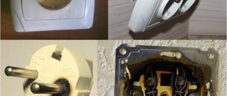
Guide to grounding an electric stove
When working in old-style networks, even qualified specialists often consciously make a grave mistake by grounding various electrical appliances to the working zero buses. Such a connection is fraught with an extremely unfavorable consequence: if the zero wire breaks, the phase will pass through the load directly to the electrical appliance and the user will be shocked.
Electricians often make another serious mistake, confusing the phase and neutral wires. When performing such “grounding”, the result will be similar to the previous case - the owner of the stove can receive an electric shock at any time. But you can’t refuse zeroing either. There are several options to solve the problem. Review the available methods and choose the one that suits your situation.
The first option is to find out whether the apartment’s switchboard is grounded
Let's find out if the apartment's shield is grounded
To do this, we go to the housing office or another service organization. If a company representative says that the shield housing is reliably grounded, all we have to do is connect the yellow-green wire to this housing through a bolt.
If a representative of the service organization gives a negative answer or is confused in his testimony, grounding cannot be performed using the method described above - it will either be ineffective or will lead to an electric shock to the user of the electric stove.
The second option is for residents of apartments on the ground floor and house owners
Ground loop diagram
Owners of such real estate can try to create a separate grounding loop. It is done like this:
- behind the outer wall of the building, three steel rods with a diameter of 16 mm and a length of 250 cm are dug into the ground;
- the buried rods are connected by a strip of steel 4 cm wide and 0.5 cm thick;
- a grounding (yellow-green) wire, previously terminated with a lug, is removed from the electrical panel;
- A wire rod is pulled from the grounding loop upward to the grounding wire. The recommended diameter of such wire is 0.8 cm. At the end of the wire rod, a steel plate with a hole for the bolt is pre-welded. The grounding cable is fastened with a bolt to the wire rod plate at a height of at least 250 cm from the ground level;
- The grounding cable is connected to a separate neutral bus in the switchboard. The grounding wire from the installed stove is connected to the same bus.
Table. The smallest dimensions of grounding conductors and grounding conductors laid in the ground
| Material | Section profile | Diameter, mm | Cross-sectional area, mm | Wall thickness, mm |
| Black steel | Round for vertical grounding conductors | 16 | — | — |
| Black steel | Round for horizontal grounding conductors | 10 | — | — |
| Black steel | Rectangular | — | 100 | 4 |
| Black steel | Angular | — | 100 | 4 |
| Black steel | Pipe | 32 | — | 3,5 |
| Galvanized steel | Round for vertical grounding conductors | 12 | — | — |
| Galvanized steel | Round for horizontal grounding conductors | 10 | — | — |
| Galvanized steel | Rectangular | — | 75 | 3 |
| Galvanized steel | Pipe | 25 | — | 2 |
| Copper | Round | 12 | — | — |
| Copper | Rectangular | — | 50 | 2 |
| Copper | Pipe | 20 | — | 2 |
| Copper | Multi-wire rope | 1,8 | 50 | — |
Third option - if grounding fails
The shield is not grounded, but it is not possible to make an individual grounding circuit? Then we simply plug the yellow-green wire and leave it in the shield until better times.
In such a situation, we pay special attention to the stove. Firstly, we install it so that there is no possibility of simultaneous user contact with the stove and various current-carrying elements such as taps, sinks, pipes, etc.
metal products
Firstly, we install it so that there is no possibility of simultaneous user contact with the stove and various live elements such as taps, sinks, pipes, etc. metal products.
Secondly, we lay, if not a special dielectric coating, then at least a thick dry mat near the electric stove.
Thirdly, we replace the conventional circuit breaker in the panel with a differential model with a 30 mA response rating.
Fourthly, we take special care and vigilance when operating an ungrounded electric stove
Important! It is impossible to ground an electric stove to water supply, sewerage and heating pipes. Although the listed elements according to the rules must be reliably grounded, no one usually controls the resistance of such grounding
The result can be a breakdown of the electrical appliance, electric shock to the user and damage to property, not only your own, but also that of your neighbors. It is also forbidden to ground electrical appliances to other utilities such as elevator shafts, ventilation ducts, etc.
Checking the operation of the electric stove
Good luck!