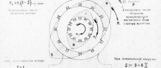
Asynchronous motor and its operation
It is obvious that the operating modes of asynchronous electric motors directly depend on their design and general operating principles. This power unit combines two key components:
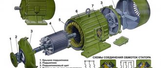
- Fixed stator. A lamellar cylinder in which a wire winding is placed in longitudinal grooves on the inner surface,
- Rotating rotor. A core (magnetic core) combined with the shaft, which contains a rod winding on the outside.
Due to the different rotation frequencies of the stator and rotor, an EMF arises between them, which sets the shaft in motion. The standard value of this parameter can reach 3000 rpm, which requires a certain effort to stop it. From logical considerations, we can conclude that since the engine starts due to EMF, then it also needs to be stopped electrodynamically.
Performance characteristics of asynchronous motor
The operating characteristics of an asynchronous motor are the dependencies P1(P2), I1(P2), M(P2), s(P2), cos f(P2), η(P2).
The performance characteristics of a 1470 rpm, 220/380 V, 50 kW squirrel-cage induction motor are plotted in relative units.
Even when the useful power is zero, a running engine consumes power from the network, called idling power P0, accordingly, current I0 flows through the stator and a torque is created on the motor shaft, called idling torque.
Performance characteristics are plotted for the power range from 0 to 1.25 Pnom.
cos f reaches its maximum value at power Pnom and remains constant as the load increases.
Efficiency reaches its maximum when magnetic losses become equal to electrical losses. Electrical machines are designed in such a way that this equality is achieved approximately at rated power.
Mechanical characteristics are also considered to be performance characteristics.
What is dynamic braking?
At this point, a logical question may arise: why invent something if you can disconnect the engine from the mains and it will stop on its own? This is undoubtedly true, but given the high rotation speed and mass-centering characteristics, it will take some time until the rotor comes to a complete stop. This period is called free run and everyone observed it in childhood, launching a simple spinning top. However, if the operation of the equipment involves frequent use of starters, then this mode leads to an obvious loss of time.
To quickly stop, braking modes are used, which involve the transformation of mechanical (in this case, kinetic) energy artificially. Everyone distinguishes two main types of inhibition, which are then divided into subtypes:
- Mechanical. The engine shaft communicates physically with the brake pads, resulting in friction, rapid stopping and heat generation,
- Electric. An asynchronous motor is stopped by converting the connection circuit, as a result of which mechanical energy is first transformed into electrical energy. Then there are two possible options for its consumption, depending on the circuit: either excess electricity is released into the backup circuit of the network, or it is transformed into heat due to heating of the windings and resistance.
Dynamic braking of an asynchronous motor is of the electrical type, since during the process the stator winding is disconnected from the AC network (two of the three phases) and transferred to a closed DC circuit. In this case, the magnetic field in the stator is converted from rotating to stationary. An EMF will still be induced in the rotor, but the torque will be directed in the opposite direction, which leads to braking.
The classic scheme, as can be seen in the illustration, involves disconnecting one phase from the network using the KM1 contactor. In this case, the other two phases, due to the KM2 contactor, are switched into a circuit with direct current through a diode bridge.
The main advantage of this method of braking is the ability to smoothly control the braking torque (by changing the voltage or resistance) and carry out an accurate stop.
Braking modes of an asynchronous motor
IM can operate in all three braking modes:
a) with energy recovery into the network;
b) opposition;
c) dynamic braking.
a) Braking with energy recovery into the network.
In the absence of external static torque on the shaft, the motor connected to the network will rotate at a speed close to synchronous. At the same time, the energy necessary to cover losses is consumed from the network. If, due to an external force, the rotor rotates at a synchronous speed, then the network will only cover the losses in the stator, and the losses in the rotor (mechanical and steel) will be covered by the external force.
In motor mode, when the rotating magnetic field crosses the conductors of the stator and rotor windings in the same direction, the emf of the stator E1 and rotor E2 are in phase. At w=w0, the EMF is not induced in the rotor, i.e. equals 0. When w>w0, the stator winding conductors are crossed by the rotating field in the same direction, and the rotor conductors are intersected in the opposite direction.
The EMF of the rotor E2 changes its sign to the opposite; the machine goes into generator mode with energy recovery. As for the current, only its active component changes its direction. The reactive component during negative slip maintains its direction. This can also be seen from the expression for the rotor current (at S<0 S2>0).
The same conclusions can be drawn based on the analysis of active (electromagnetic) and reactive powers. Indeed, from the expression for SEM it follows that when S<0 PEM>0 i.e. active power changes direction (transmitted to the network), and from the expression for Q2 it follows that when S<0, the reactive power of the secondary circuit Q2 retains its sign regardless of the operating mode of the machine.
This means that an asynchronous machine, both in motor and generator modes, consumes reactive power necessary to create a magnetic field.
Braking with energy release into the network is used in lifting and transport installations when lowering heavy loads. Under the influence of the load, the rotor of the machine will rotate at a speed w>w0, the machine goes into generator mode and begins to create a braking torque. If M=Mc is equal, the load will fall at a steady speed wc, as shown in the figure. It must be borne in mind that to ensure normal descent of the load, Mc should not exceed the critical moment in generator mode. With a reactive moment of resistance, a short-term mode with energy recovery into the network can be obtained if the IM allows the stator winding to switch from one pair of poles to another, as shown in the graph above.
The recuperation mode takes place in the BC section after switching the stator winding from the number of pole pairs rP=1 to rP=2.
b) braking by counter-switching.
In reverse mode, the motor rotor rotates in the direction opposite to the motor torque. Its slip is S>1, and the frequency of the current in the rotor is greater than the frequency of the supply network ( ). Therefore, despite the fact that the rotor current is 7–9 times greater than the rated current, i.e. greater than the starting current, the torque due to the high frequency of the current, therefore the large inductive reactance of the rotor circuit ( ), will be small. Therefore, to increase the torque and simultaneously reduce the current, a large additional resistance is included in the rotor circuit, the value of which can be calculated by the expression
Where E20 is the rated EMF of the rotor at S=1
Sн – nominal slip
Sн and – sliding at rated load on an artificial characteristic.
When lowering a load in the back-to-back mode, braking occurs in a straight section of the mechanical characteristic, the rigidity of which is determined by the active resistance in the rotor circuit. The mechanical characteristics of the IM during the braking descent of the load in the counter-switching mode are shown in the figure. To brake by back-switching during reactive torque, it is necessary to change the order of the supply voltage phases while the engine is running and at the same time introduce additional resistance into the rotor circuit in order to limit the initial inrush current and simultaneously increase the braking torque. The mechanical characteristic in this case looks as shown in the figure. Braking by counter-connection of the RAD with a reactive torque of resistance is not effective, since the initial braking torque when sliding is close to 2, due to the large reactance equal to , will be insignificant (see Fig. segment).
c) dynamic braking with independent direct current excitation
When the IM stator winding is disconnected from the network, only a slight magnetic flux from the residual magnetization of the stator steel is retained. The EMF induced in the rotating rotor and the current in the rotor will be very small. The interaction of the rotor current with the flux from residual magnetization cannot create any significant electromagnetic torque. Therefore, to obtain the proper braking torque, it is necessary to artificially create the proper stator magnetic flux. This can be achieved by supplying direct current to the stator windings or connecting capacitors or a thyristor frequency converter to them, ensuring capacitive current flows through the stator windings, i.e. leading current, creating a capacitance effect. In the 1st case, there will be a dynamic braking mode with independent excitation, in the 2nd case - with self-excitation.
With dynamic braking with independent excitation, the stator windings are disconnected from the three-phase current network and connected to a direct current source. This current creates a magnetic flux stationary in space, which, when the rotor rotates, will induce an emf in the latter. Under the influence of EMF, a current will flow in the rotor windings, the interaction of which with a stationary flow causes a braking torque. The motor is converted into a non-salient pole synchronous generator operating at variable speed.
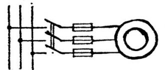
Symmetrical connection of 3 stator windings to a DC network is impossible without switching them. Usually one of the schemes shown in Fig. is used.
Since when powered by direct current the windings have only ohmic resistance, a small voltage is sufficient to obtain the desired current value. Semiconductor rectifiers are used as a DC source for small and medium power motors, and special low voltage DC generators can be used for large motors.
To derive the equation for the mechanical characteristics of the IM in the dynamic braking mode, it is advisable to replace the synchronous generator mode into which the IM turns after connecting to a direct current source with an equivalent mode of the IM, assuming that its stator is powered by alternating current instead of a constant one. With such a replacement, the MMF is created jointly by the stator and rotor windings and the equality of the MMF must be observed for both cases, i.e. FCONT = FPER. The definition of MMF created by direct current IPOST for circuit “a” is explained in Fig. and vector diagram shown side by side.
. The amplitude of the MMF created by alternating current I1 as it flows through the stator windings: . Based on the condition. Hence the value of alternating current equivalent to direct current: , a . Required DC voltages and power: .
Having determined the current I1, the car in braking mode can be represented as a normal blood pressure. However, AM operation in dynamic braking mode differs significantly from operation in normal motor mode. In the motor mode, the magnetizing current and magnetic flux practically do not change when the slip changes. During dynamic braking, the magnetic flux changes when the slip changes due to a continuous change in the resulting MMF, which consists of a constant MMF of the stator (direct current) and a changing MMF of the rotor (alternating current of variable frequency).
The resulting magnetizing current reduced to the number of turns of the stator winding. From the vector current diagram it follows:
By squaring these expressions and adding them term by term, we get: The magnetizing current is equal to .
In a reduced machine, where E2' is the rotor EMF at synchronous speed w0, corresponding to the network frequency. For w different from w0, the rotor EMF will be equal to: , where n is the relative speed or otherwise, sliding in dynamic braking mode. In this case, the EMF equilibrium equation for the rotor circuit has the form: , and the magnetizing current, expressed through E2': .
The total resistance of the rotor, taking into account the fact that its inductive reactance changes with the rotor speed: .
Taking into account that and substituting the values of Im, siny2 and Z2' into the equation for I12, from the resulting relationship the current I2' is found, which will be equal to: .
Electromagnetic torque developed by the motor, expressed in terms of electromagnetic power: , where m1 is the number of phases of the stator winding.
From the expression for M it is clear that the torque during dynamic braking is determined by the alternating current I1, equivalent to the direct current flowing through the stator windings.
Taking the derivative and equating it to 0, we find that the moment will be maximum at the relative speed: , and the value of this moment, also called critical, is equal to: .
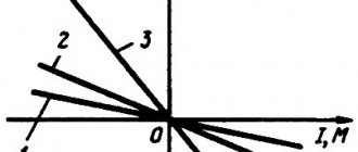
Mechanical characteristics at different values of direct current and different resistance of the rotor circuit are shown in the figure. Curves 1 and 2 correspond to the same value of rotor circuit resistance and different values of direct current in the stator, and curves 3 and 4 correspond to the same values of direct current, but higher resistance of the rotor circuit.
From the expression for MK it follows that the critical torque of the engine in dynamic braking mode does not depend on the active resistance of the rotor circuit.
By dividing the value of M by the value of MK, the equation of mechanical characteristics can be given the form: .
IM can operate in all three braking modes:
a) with energy recovery into the network;
b) opposition;
c) dynamic braking.
a) Braking with energy recovery into the network.
In the absence of external static torque on the shaft, the motor connected to the network will rotate at a speed close to synchronous. At the same time, the energy necessary to cover losses is consumed from the network. If, due to an external force, the rotor rotates at a synchronous speed, then the network will only cover the losses in the stator, and the losses in the rotor (mechanical and steel) will be covered by the external force.
In motor mode, when the rotating magnetic field crosses the conductors of the stator and rotor windings in the same direction, the emf of the stator E1 and rotor E2 are in phase. At w=w0, the EMF is not induced in the rotor, i.e. equals 0. When w>w0, the stator winding conductors are crossed by the rotating field in the same direction, and the rotor conductors are intersected in the opposite direction.
The EMF of the rotor E2 changes its sign to the opposite; the machine goes into generator mode with energy recovery. As for the current, only its active component changes its direction. The reactive component during negative slip maintains its direction. This can also be seen from the expression for the rotor current (at S<0 S2>0).
The same conclusions can be drawn based on the analysis of active (electromagnetic) and reactive powers. Indeed, from the expression for SEM it follows that when S<0 PEM>0 i.e. active power changes direction (transmitted to the network), and from the expression for Q2 it follows that when S<0, the reactive power of the secondary circuit Q2 retains its sign regardless of the operating mode of the machine.
This means that an asynchronous machine, both in motor and generator modes, consumes reactive power necessary to create a magnetic field.
Braking with energy release into the network is used in lifting and transport installations when lowering heavy loads. Under the influence of the load, the rotor of the machine will rotate at a speed w>w0, the machine goes into generator mode and begins to create a braking torque. If M=Mc is equal, the load will fall at a steady speed wc, as shown in the figure. It must be borne in mind that to ensure normal descent of the load, Mc should not exceed the critical moment in generator mode. With a reactive moment of resistance, a short-term mode with energy recovery into the network can be obtained if the IM allows the stator winding to switch from one pair of poles to another, as shown in the graph above.
The recuperation mode takes place in the BC section after switching the stator winding from the number of pole pairs rP=1 to rP=2.
b) braking by counter-switching.
In reverse mode, the motor rotor rotates in the direction opposite to the motor torque. Its slip is S>1, and the frequency of the current in the rotor is greater than the frequency of the supply network ( ). Therefore, despite the fact that the rotor current is 7–9 times greater than the rated current, i.e. greater than the starting current, the torque due to the high frequency of the current, therefore the large inductive reactance of the rotor circuit ( ), will be small. Therefore, to increase the torque and simultaneously reduce the current, a large additional resistance is included in the rotor circuit, the value of which can be calculated by the expression
Where E20 is the rated EMF of the rotor at S=1
Sн – nominal slip
Sн and – sliding at rated load on an artificial characteristic.
When lowering a load in the back-to-back mode, braking occurs in a straight section of the mechanical characteristic, the rigidity of which is determined by the active resistance in the rotor circuit. The mechanical characteristics of the IM during the braking descent of the load in the counter-switching mode are shown in the figure. To brake by back-switching during reactive torque, it is necessary to change the order of the supply voltage phases while the engine is running and at the same time introduce additional resistance into the rotor circuit in order to limit the initial inrush current and simultaneously increase the braking torque. The mechanical characteristic in this case looks as shown in the figure. Braking by counter-connection of the RAD with a reactive torque of resistance is not effective, since the initial braking torque when sliding is close to 2, due to the large reactance equal to , will be insignificant (see Fig. segment).
c) dynamic braking with independent direct current excitation
When the IM stator winding is disconnected from the network, only a slight magnetic flux from the residual magnetization of the stator steel is retained. The EMF induced in the rotating rotor and the current in the rotor will be very small. The interaction of the rotor current with the flux from residual magnetization cannot create any significant electromagnetic torque. Therefore, to obtain the proper braking torque, it is necessary to artificially create the proper stator magnetic flux. This can be achieved by supplying direct current to the stator windings or connecting capacitors or a thyristor frequency converter to them, ensuring capacitive current flows through the stator windings, i.e. leading current, creating a capacitance effect. In the 1st case, there will be a dynamic braking mode with independent excitation, in the 2nd case - with self-excitation.
With dynamic braking with independent excitation, the stator windings are disconnected from the three-phase current network and connected to a direct current source. This current creates a magnetic flux stationary in space, which, when the rotor rotates, will induce an emf in the latter. Under the influence of EMF, a current will flow in the rotor windings, the interaction of which with a stationary flow causes a braking torque. The motor is converted into a non-salient pole synchronous generator operating at variable speed.
Symmetrical connection of 3 stator windings to a DC network is impossible without switching them. Usually one of the schemes shown in Fig. is used.
Since when powered by direct current the windings have only ohmic resistance, a small voltage is sufficient to obtain the desired current value. Semiconductor rectifiers are used as a DC source for small and medium power motors, and special low voltage DC generators can be used for large motors.
To derive the equation for the mechanical characteristics of the IM in the dynamic braking mode, it is advisable to replace the synchronous generator mode into which the IM turns after connecting to a direct current source with an equivalent mode of the IM, assuming that its stator is powered by alternating current instead of a constant one. With such a replacement, the MMF is created jointly by the stator and rotor windings and the equality of the MMF must be observed for both cases, i.e. FCONT = FPER. The definition of MMF created by direct current IPOST for circuit “a” is explained in Fig. and vector diagram shown side by side.
. The amplitude of the MMF created by alternating current I1 as it flows through the stator windings: . Based on the condition. Hence the value of alternating current equivalent to direct current: , a . Required DC voltages and power: .
Having determined the current I1, the car in braking mode can be represented as a normal blood pressure. However, AM operation in dynamic braking mode differs significantly from operation in normal motor mode. In the motor mode, the magnetizing current and magnetic flux practically do not change when the slip changes. During dynamic braking, the magnetic flux changes when the slip changes due to a continuous change in the resulting MMF, which consists of a constant MMF of the stator (direct current) and a changing MMF of the rotor (alternating current of variable frequency).
The resulting magnetizing current reduced to the number of turns of the stator winding. From the vector current diagram it follows:
By squaring these expressions and adding them term by term, we get: The magnetizing current is equal to .
In a reduced machine, where E2' is the rotor EMF at synchronous speed w0, corresponding to the network frequency. For w different from w0, the rotor EMF will be equal to: , where n is the relative speed or otherwise, sliding in dynamic braking mode. In this case, the EMF equilibrium equation for the rotor circuit has the form: , and the magnetizing current, expressed through E2': .
The total resistance of the rotor, taking into account the fact that its inductive reactance changes with the rotor speed: .
Taking into account that and substituting the values of Im, siny2 and Z2' into the equation for I12, from the resulting relationship the current I2' is found, which will be equal to: .
Electromagnetic torque developed by the motor, expressed in terms of electromagnetic power: , where m1 is the number of phases of the stator winding.
From the expression for M it is clear that the torque during dynamic braking is determined by the alternating current I1, equivalent to the direct current flowing through the stator windings.
Taking the derivative and equating it to 0, we find that the moment will be maximum at the relative speed: , and the value of this moment, also called critical, is equal to: .
Mechanical characteristics at different values of direct current and different resistance of the rotor circuit are shown in the figure. Curves 1 and 2 correspond to the same value of rotor circuit resistance and different values of direct current in the stator, and curves 3 and 4 correspond to the same values of direct current, but higher resistance of the rotor circuit.
From the expression for MK it follows that the critical torque of the engine in dynamic braking mode does not depend on the active resistance of the rotor circuit.
By dividing the value of M by the value of MK, the equation of mechanical characteristics can be given the form: .
Main types of dynamic braking
Organizing a forced stop of an asynchronous motor using the electrical principle can be carried out in several ways:
- Electrodynamic. This is a classic option, in which two phases need to be short-circuited and transferred to DC power,
- Regenerative (generator). Characterized by the return of excess electricity to the network,
- Anti-inclusion. This option is implemented using a reverse circuit, that is, with the phases connected through a pair of magnetic starters,
- Self-excitation. By connecting a battery of capacitors to the stator windings.
Generator braking of an asynchronous motor
Asynchronous motors are used with such production mechanisms, under the influence of which their rotation speed cannot become greater than ω0, in other words, the engine cannot switch to generator mode under the action of the production mechanism. Generator mode occurs in asynchronous motors, the speed of which is regulated by changing the number of pole pairs. At the moment of switching from one number of pole pairs to another, a current surge occurs in the motor stator circuit, and it switches to the generator mode of operation.
Characteristics of an asynchronous motor with regenerative (generator) braking.
Classic dynamic braking
The effectiveness of this operating mode depends on the calculation and value of the following parameters:
- The amount of current that is supplied through a parallel circuit to the stator windings. The higher this indicator, the greater the braking torque,
- The amount of resistance that is introduced into the rotor circuit. The higher the calculated resistance, the faster the engine decelerates,
- The magnitude of the magnetic driving force (MDF). Sometimes it is called ampere turns, since the calculation is carried out using the formula F = I × W, where I is the current value and W is the number of turns.
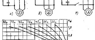
The stator winding can be connected in at least five different ways:
- Triangle,
- Triangle with shorted phases,
- A star
- A star with a short-circuited zero,
- A star with two phases shorted.
In each case, based on the vector diagram, the MMF, braking resistance and circuit voltage are calculated.
How to select a braking resistor for a frequency converter
Drives of cranes, conveyors and other industrial equipment operating in intermittent modes with frequent switching on, switching off and reversing are equipped with braking devices that ensure quick stop of the electric motor.
For this purpose, electrodynamic and mechanical methods are used. Electrodynamic braking is achieved:
- By applying constant voltage to the stator windings. In this case, a stationary magnetic field arises, creating a braking torque.
- Changing the phase connection order. The magnetic field begins to rotate in the direction opposite to the direction of rotation of the rotor of the electric machine.
In both cases, a negative torque occurs on the electric motor shaft, ensuring a quick stop. This is necessary for inertial mechanisms with high loads.
In many industrial systems, motors are stopped simply by natural deceleration . The time spent on this depends solely on the inertia and resistive torque of the engine. However, times often need to be reduced, and electric braking is a simple and effective solution.
Electrical Braking of Induction Motors - A Guide (photo credit: Chris Shontz via Flickr)
Compared with mechanical and hydraulic brake systems, it has the advantage of stability and no wear parts.
Electric Braking Options Seen in This Article //
- Countercurrent braking Squirrel-cage motor
- Slipper ring motor
Countercurrent braking. Principle
The motor is isolated from the mains while it is still running and then reconnected in reverse. This is a very effective braking system with a torque , usually greater than the starting torque, which must be stopped early enough to prevent the engine from moving in the opposite direction.
Several automatic devices are used to control the stop once the speed is almost zero:
- Friction stop detectors, centrifugal stop detectors,
- Chronometric devices,
- Frequency measurements or rotor voltage relays (slip ring motors), etc.
1.1 Squirrel-cage motor
Before selecting this system (Figure 1), it is important to ensure that the motor can withstand countercurrent braking at the required load. In addition to mechanical stress, this process exposes the rotor to high thermal loads as the energy released during each braking operation (sliding energy from the mains and kinetic energy) is dissipated in the cage.
The thermal stress during braking is three times greater than during acceleration .
Figure 1 — The principle of countercurrent braking
During braking, the current and torque peaks are noticeably higher than during starting.
For smooth braking, a resistor is often installed in series with each stator phase when switching to countercurrent. This reduces the torque and current, as when starting a stator. The disadvantages of countercurrent braking in squirrel-cage motors are so great that this system is used only for some applications with low-power motors .
1.2 Sliding motor
To limit current and torque before the stator switches to countercurrent, it is critical to reinsert the rotor resistors used for starting , and frequently add an additional braking section (see Figure 2).
Figure 2 - The principle of countercurrent braking in an asynchronous sliding machine
With the correct rotor resistor, it is easy to adjust the braking torque to the required value. When current is switched, the rotor voltage is nearly twice as high as when the rotor is at rest, sometimes requiring special insulation precautions.
As with power motors, a large amount of energy is released in the rotor circuit . It is completely dissipated (minus a few losses) in resistors.
The motor can be stopped automatically by one of the above devices or by a voltage or frequency relay in the rotor circuit. With this system, the driving load can be maintained at a moderate speed. The characteristic is very unstable (wide variations in speed versus small variations in torque).
Return to Electric Braking Options ↑
DC injection braking
This electric braking system is used on slip and squirrel cage motors (see Fig. 3). Compared to a countercurrent system, the cost of a rectified current source is offset by fewer resistors . Thanks to electronic speed controllers and starters, this braking option does not add to the cost.
The process involves isolating the stator from the mains and applying rectified current to it . The rectified current creates a fixed flux in the air gap of the motor. For this flux value, the current must be approximately 1.3 times the rated current to ensure proper braking.
The excess heat loss caused by this small excess current is usually compensated for by a pause after braking .
Regenerative braking
Regenerative braking mode
Since the excess electricity released during braking is sent back to the network through the bridge/capacitor bank, this mode of operation is considered the most economical. Most often, this method is used in lifting and transport equipment and equipment that works to move loads or its own weight downhill. A classic example is an elevator, where regenerative braking from the drive motor is used for initial braking. Also, a similar scheme is widely used in electrified transport, for example, in trams, trolleybuses, and electric trains. It is also used in special equipment, for example, excavators, widely used in the construction of bridges, roads, buildings, etc.
The principle of calculation and organization of the generator mode is that the rotor speed exceeds its synchronous value. In this case, the electromagnetic torque changes direction, which leads to braking.
Back braking
Back-up braking circuit
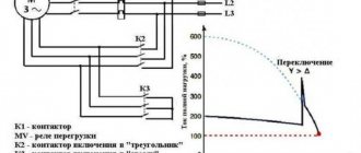
In practice, the opposition regime can be organized in several different ways. The classic method is to use a pair of magnetic starters connected in a reverse circuit. In this case, a quick stop of the unit is carried out by changing the position of the phases (counter-switching).
The main starter KM2 disconnects the motor M from the network. After this, the parallel starter KM1 turns on the engine again, changing the extreme phases in places, that is, forcing it to rotate in the opposite direction. To prevent excessive overheating, additional resistance can be introduced into the circuit. Also, a counter-connection circuit can be implemented if the engine is used as a brake for a load.
Self-excitation inhibition
Self-excitation braking circuit
This option is implemented by connecting the stator windings to a parallel capacitor bank or bridge (the capacitance will have to be calculated). When the motor is disconnected from the network and the coasting mode must occur, the fading magnetic field begins to power the capacitors, and through them returns back to the winding, creating a braking torque.
As you can see, in practice, a whole range of specific operating modes of asynchronous motors is used, which can be used to quickly and accurately stop it. With frequent starts and stops, dynamic, regenerative, reverse (on starters) or capacitor braking (through bridge or battery calculation) can increase the efficiency of equipment operation and reduce time loss.