When a light switch fails, it becomes necessary to disassemble it. If it is discovered that the device does not work, the first step is to determine whether there is voltage in the apartment network. Then you need to remove the light bulb connected to the switch and check the serviceability of it and the socket. It often happens that the fault turns out to be somewhere else. If there is electricity in the rooms and the light bulb and socket are in order, the cause of the malfunction most likely lies in the switch itself.
How to disassemble a light switch yourself
Before removing the switch, you need to determine its type. It could be as follows:
- One-, two- or three-key.
- Passage. In fact, it is a contact switch and is similar to a switch only in appearance.
- Dimmer – a switch with a built-in device for regulating the brightness of incandescent and halogen lamps. It can be mechanical or with a microcontroller.
- Pulse - a button connected by contacts to a special relay;
- Touch – acoustic (triggered by a loud sound), controlled from an IR remote control or radio remote control.
Most users use key switches, which are worth considering first.
Power outage
Before removing an outlet or light switch, first turn off the electricity. In the room, the electrical wiring branches into several lines: sockets, lighting and leads to the electric stove. At the switchboard, the lighting power is turned off automatically, and then the absence of voltage is checked at its output.
Sometimes it turns out that it is not the phase wire that is connected to the machine, but the neutral wire. This can be done by an unqualified electrician who assembled the panel circuit. The circuit will work, but the lighting wiring will be constantly energized, regardless of whether the circuit breaker is turned on or not. If such an error is found, it should be eliminated by making the necessary changes to the circuit.
If you have difficulty choosing a line, you can turn off the input machine, turning off the power to the entire apartment.
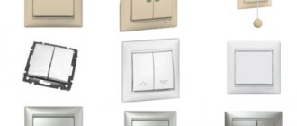
Main types of light switches
There are two main types of wall mounting designs, which are fundamentally different:
- for hidden wiring;
- for external wiring.
To avoid mistakes:
- short circuit;
- burnout of expensive lighting fixtures, energy-saving, LED or fluorescent lamps;
- burning of insulation in a junction box or wall;
- electric shock.
Necessary:
- Familiarize yourself with the basic rules of safety measures. Before removing the switch, you need to study the design of their fastening and connection. Products for external wiring are fastened with ordinary dowels and self-tapping screws, and the housing is pressed against the wall through the mounting holes. For internal wiring models, fastening technologies are more complex. The design of the case includes a mechanism of sliding strips, which fix the case on two opposite sides in a pre-made hole with a diameter of 67-70 mm.
To save on electricity bills, our readers recommend the Electricity Saving Box. Monthly payments will be 30-50% less than they were before using the saver. It removes the reactive component from the network, resulting in a reduction in load and, as a consequence, current consumption. Electrical appliances consume less electricity and costs are reduced.
- Regardless of the type of light switch, for what purpose it has to be disassembled, first of all at the distribution board, the circuit breaker is turned off. This is done for safety reasons to prevent the possibility of electric shock to working people. You need to make sure that the shutdowns are made correctly, click the keys several times, the lighting devices should not work. According to the requirements of the PUE (Electrical Installation Rules), a sign must be hung on the circuit breaker in the switchboard: “Do not turn on people working.” It is advisable to close the cabinet and keep the keys with you so that strangers do not have access to the switches. Having completed these steps, you can begin to disassemble the switch itself.
How to disassemble a switch
Disassembly tools will require a flathead and Phillips screwdriver. Most models use flat mounting screws, but sometimes you can find cross-shaped ones.
Switches come with one, two or three keys. Without removing them, the device cannot be disassembled, since the fastening elements are hidden inside.
The devices vary in design, and disassembly methods may vary:
- The key is pressed against the wall with your thumb on one edge and is removed if you pull the other one towards you (Fig. a). You should not pick it with a screwdriver or knife, as scratches will remain on the surface. Some keys fit tightly and can be pryed off by the edge with a screwdriver.
- The key is pressed on the sides with your fingers, the fastenings are recessed, and it moves freely.
- If there are connectors on the sides, pry them up with a screwdriver and gently pull them towards you, after which the key comes off.
Removing the keys (a) and frame (b) from the switch with your own hands
Double and triple keys are removed in turn. Then you need to remove the decorative frame, which is pressed against the mechanism by an insert located in the middle and held by latches. It should be removed by prying the edge with a screwdriver (Fig. b).
Afterwards, the fastening elements for the wiring and the switch mechanism will become accessible.
Switch mechanism with wire fastening elements
The frame may be secured with screws that need to be unscrewed. Most often it is fixed on the side latches. The plastic fasteners bend one by one and the frame comes off.
Before dismantling the mechanism, you need to find the core through which the phase is connected to the switch. To do this, voltage is applied to it, and the indicator checks the presence of voltage on both contacts. Then the key switches to the next position and the test is repeated.
If in all cases voltage remains on one contact, it means that the supply phase conductor is connected to it. The other core will go to the lamp. The phase for two- and three-key switches is found similarly. The home handyman should not be concerned about the number of wires connected. Among them there will be only one wire through which the supply voltage is supplied. The power supply is then switched off again and operation continues.
The fastening screws hold the spacer tabs that rest against the side walls of the mounting box. If you loosen the screws, the mechanism will freely come out of the wall. If it is secured to the box with screws, they should be removed.
Then unscrew the screws securing the wires and remove it from the wall recess. Check the absence of voltage on the mechanism using an indicator screwdriver. The input conductors can be secured with self-clamping terminals. To easily pull the wires out of the connector, press the locking levers. First, the phase wire is disconnected and insulated. Subsequently, it is reconnected to the phase contact of the new or repaired switch. If the pins are marked "L" and "1", the connection is made to "L". When they are designated “1” and “2”, the phase is connected to contact “1”.
Designation of contact L of the supply phase
In two- and three-key switches, the contacts are designated in a similar way:
- two-key – “L”, “1”, “2” or “1”, “2”, “3”;
- three-key – “L”, “1”, “2”, “3” or “1”, “2”, “3”, “4”.
In all cases, the devices have one common contact with the connected supply phase and outlet contacts to the lamps.
The phase connection must be to a fixed contact, and the outlet wire to a moving one. If everything is done correctly, the key will be pressed from above in the “on” position and from below in the “off” position.
After disassembly, the switch in a particular case looks as shown in the figure below (LEZARD brand). It contains 3 main elements: mechanism, frame and key.
What does a disassembled switch look like?
Disassembling the external wiring switch
For external wiring structures, the disassembly sequence is similar, but it is necessary to take into account that instead of the screws of the spacer mechanism, screws are unscrewed that press the housing directly to the wall. The safety measures are the same, for reliability you can wear dry household rubber gloves, the voltage is low, this will be quite enough for protection. All operations can be done with one indicator screwdriver.
When operating household networks, switching switches and sockets are used to connect electrical appliances and room lighting. Due to natural aging, emergency conditions and excessive load, switches can fail. Therefore, the question may often arise about how to disassemble a light switch with your own hands.
Why disassemble the switch?
The most common reasons are:
- Transforming the aesthetic appearance by replacing outdated models with more modern ones;
- The appearance of an unpleasant burning smell from the switch or its excessive heating;
- The lighting device powered by the switch does not turn on or malfunctions;
Therefore, disassembly is caused either by some kind of emergency situation or by its obsolescence. Let's consider the procedure for disassembling the switch.
#1. Turn off the voltage
Rice. 1: disable double machine
The main step, before disassembling the switch, is to remove the voltage from all current-carrying elements that are involved in the power supply. As with disassembling sockets, the best option for de-energizing is to turn off the input circuit breakers. If your machine breaks two wires at once - both phase and zero, then after turning it off, you can immediately disassemble the switch.
Rice. 2: disable single machine
If there is one machine at the input and you do not know whether it disconnects the phase wire or not, then after switching it you need to use an indicator screwdriver. Which will allow you to determine the presence or absence of potential in the network. If the potential is still present on the electrical wire, then you need to turn off the phase at the distribution board or use dielectric gloves and safety glasses when disassembling the switch.
If the apartment has its own distribution panel, in which the circuit breakers are not labeled and you do not know the connection diagram, then turn off each circuit breaker one by one and observe the state of the light bulb when the switch is on. If the switch is broken and you are unable to supply voltage to the light bulb, use an indicator to check the voltage in nearby outlets, and if there are none, turn off the voltage in the apartment completely. Or use dielectric gloves.
Rice. 3: Use dielectric gloves if you cannot turn off the power to the switch.
#2 Remove the keys
In most cases, to disassemble modern switches, it is necessary to remove the keys. Since they act as a decorative panel that hides the place where the switch itself is attached to the wall or box. In some older models, dismantling the key is not required, since their attachment points are located directly on the body, and the key performs only its direct function.
Rice. 4: modern two-gang switch
Look at the picture, here is an example of a two-key switch. In a model with large keys that occupy a significant area of the device, you need to lightly press on one side of the key, lock it in the extreme position, and pull it towards you.
Rice. 5: Pull the key towards you
Some switch designs even provide a small recess for this purpose, into which it is convenient to place your fingers and then remove the keys from there.
Rice. 6: the key came off easily
If you cannot pull the key with your fingers or the force applied is not enough, you can use a flat tool. To remove the key, pry it from the side with a regular screwdriver.
Rice. 7: pry up the key with a screwdriver
Be careful when doing this as you can easily damage the key. Of course, you don’t have to regret the device being prepared for disposal, but in other situations you need to be extremely careful. If necessary, you can pry the key alternately from different sides to ensure its forward movement. You should end up removing all the keys.
Rice. 8: switch without keys
#3 Remove the cover
In various models, the cover can be fixed using:
Rice. 10: fastening with frame
Look, the frame is fixed with small latches, there are four of them in this model. In order to remove the frame, it is enough to pry off two adjacent ones, and the rest can be easily pulled out from their mounting points.
After the decorative cover and key are removed, you can proceed to removing the mechanism body itself.
If there are bolts on the outside of the old cover, disassembly should begin by removing these bolts.
Rice. 11: Unscrew the bolts on the cover
Then proceed to unscrew the housing.
#4 Remove the housing
The most common option on new rocker switches is a bolt-on design located at the edges of the housing that secures the entire mechanism into the box. To remove from the body, the bolts at the attachment points are unscrewed one by one.
Rice. 12: Unscrew the housing bolts
The second fixation option is spring spacers, which, in addition to mounting in the box, also allow you to adjust the angle of rotation of the main block of the automatic switch. In such a situation, use a screwdriver to loosen the spacers until the switch freely comes out of the socket. This is done by unscrewing the bolts.
Rice. 13: loosen the spacers
In models with a bolt-on housing, you can also see these spacers that allow you to adjust the angle of rotation. But you don’t need to unscrew them to disassemble the device.
It should be noted that in the event of a breakdown, it is possible that the wires are burnt away from the fastening or they become loose at the crimp points. Then the core may fall out of the box. Such a fall with the voltage turned off, although safe from the point of view of electric shock, nevertheless, the main part of the switch may be damaged if dropped. Therefore, before removing the mechanism, it is better to support it with your fingers during dismantling.
Once the switch core is pulled out of the box, it should remain hanging by the wires alone.
Rice. 14: core on wires
Therefore, to disassemble it further, disconnect the wiring fastener from the slats. The supply wires may have different methods of attachment to the lamellas, which is why their disconnection will be different. The most common options are:
- Fixation with screws - in this case they are simply unscrewed with a screwdriver;
- Fixation using clamps - in order to disassemble the fastening of the wires, you just need to press on the corresponding levers.
- Using crimping is a fairly old method; it is not used in modern models, since unclamping the sleeve is a rather labor-intensive task and its reuse is not always possible.
- By twisting - the rules prohibit the use of twists, but in practice you can easily encounter such a connection. Which often becomes the cause of malfunction or failure of the electrical switch.
Rice.
15: Disconnect the wires It should be noted that this procedure should be done carefully so that small parts do not fall apart. If your goal was to install a new double switch, you can simply throw away the old one. And if you disassembled the device to eliminate any malfunction, then after disconnecting the wire it must be inspected.
#6 Inspect the switch
If your goal was to identify any faults, carefully inspect the mounting locations of the phase leads. It is possible that traces of melting or oxidation will be clearly visible on them. If there is thermal destruction of the plastic, you can immediately replace the entire switch. Oxidation areas can cause poor contact, so they need to be cleaned.
Due to the fact that its cost is relatively low, it is simply impractical to make any replacements of parts and places where the housing is attached to damaged parts.
There is also a possibility that the switch remained intact, but the electrical wiring suffered from excessive overheating. In such situations, you may observe annealing of live parts, melting of insulation and other damage. These factors will indicate that it may be necessary to replace the wiring or some section of it.
If all parts do not contain any signs of burning, then there may be no contact in the on position. To check for such a malfunction, use a multimeter and check for the presence or absence of contact. In some models, it is enough to simply get to the mechanism and restore its normal operation. Therefore, it is quite possible to fix such a malfunction yourself.
Switch connection. Video
The video talks about how to properly connect a single switch to the network.
The method of disassembling a switch depends on its design. You should remove the keys and decorative frame carefully, since the fastenings are mostly made using plastic latches of different designs. Work on disassembling the switch should be carried out with the mains voltage turned off.
The switch is considered the main device that helps control lighting. Today the following types are common: single, double and triple. The last type is designed for connecting several lamps, that is, for combined lighting.
General view of a three-key switch with a socket
Disassembling the internal wiring switch
- Remove the plastic key strips and decorative cover from the switch.
On older models, to remove the decorative cover, you just need to unscrew two screws; they are located on the surface. In new models, these bolts are hidden under the keys, which are easily removed with your fingers or can be pryed off with a screwdriver.
Only then will you gain access to the screws securing the top cover. After removing the decorative elements, you will see the housing in the mounting hole. If it is fixed by a conscientious electrician, you will not be able to pry it with a screwdriver and pull it out.
- Unscrew the two screws of the spacer mechanism counterclockwise; the fixing strips will move away from the wall.
In some models, along the perimeter of the structure there is a galvanized plate with holes for fastening the housing with self-tapping screws to the wall. The plate has holes for attaching the housing to plastic socket boxes, which have channels for fastening screws.
There are cases when the entire structure is supported only by a spacer mechanism, or perhaps screwed to the wall and socket box. Check all the options, disconnect all the fasteners, after which the entire mechanism can be removed from the mounting hole by hand without much effort.
- Once again, use an indicator screwdriver to check the absence of voltage on all contacts. After making sure that there is no danger, disconnect the wires from the terminals. In cases where the terminals are stuck, the insulation and the housing have melted, you cannot unscrew the bolts on the contacts with a screwdriver, bite off the wire with wire cutters. It is necessary to bite off the wire so that no burnt insulation remains, at the same time, the length is sufficient for installing a new product. When the wires remain too short, it is not recommended to lengthen them by twisting them; the best option is to replace them along the entire section from the box to the switch, this is another topic.
Applications, Benefits and Methods of Use
A three-key switch with a socket, despite its ease of operation, is rarely installed. The connection diagram for a three-key switch with a socket is more complicated than a regular one, because there are three contacts going to the lighting device at once. This unit has many functions and takes up minimal space, since three devices are located in one housing.
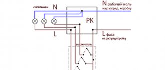
Three-key switch connection diagram
The socket is a separate device. Although it is located in one building, it works independently. “Zero” from the distribution box goes to it, and “phase” is connected from the switch jumper.
Among the advantages of such a three-key switch are:
- saving electricity;
- compactness;
- the ability to control lighting in various rooms;
- easy regulation and switching of the light source (if dimmers are not used);
- possibility of combining lighting.
The use of a three-key switch is necessary for:
- changes in lighting intensity;
- control several lamps simultaneously.
If the device is equipped with a block with a socket, then it is considered the most functional.
How to choose and correctly connect a three-key switch - we consider carefully
Published by Artyom on 03/27/2019 03/27/2019
In order to save a little energy, as well as control different levels of lighting from one place, light switches with three keys were created. They are often used in houses and apartments because... really convenient and easy to use. Connecting a triple model is more difficult than a single one, so this article provides you with video and photo examples, as well as a wiring diagram for a three-key light switch.
Where are they used?
Modern renovations and design solutions increasingly suggest dividing lighting into different groups.
For example, a room has a complex configuration - niches, ledges, separation by partitions or curtains. Very often now large one-room apartments are divided into zones and made into so-called studios. In this case, a switch with three keys is ideal. By using specially thought-out and mounted zone lighting, you can highlight a work area where there will be a computer desk, a sofa, shelves with books, here the lighting is made brighter. The second zone is the sleeping area, where more subdued light is quite suitable. The third zone is the living room, where there is a coffee table, armchairs, and a TV; here the lighting can be combined.
When else is it advisable to use a three-key household switch?
- If from one point it is necessary to control the lighting of three rooms at once, for example, a corridor, a bathroom and a bathroom, when they are located close to each other.
- In the case of combined lighting in the room - central and spot.
- When in a large room, lighting is provided by a multi-arm chandelier.
- If the room has a multi-level ceiling made of plasterboard sheets.
- When the lighting of a long corridor is divided into three zones.
Operation of a circuit with a three-key switch
When you press, for example, the right key, the right contact closes and the phase with wire L1
enters the junction box, where through point
2
and the ceiling wire it reaches the brown terminal of the
HL1
and the lamp lights up.
Zero N
common
for all lamps .
Remember
.
The phase reaches the upper contacts of the switch only when the contact of the corresponding key is closed
.
Now, when you press the middle key, the middle contact closes, and the phase with wire L2
enters the junction box, where through point
3
and the ceiling wire it reaches the brown terminal of the
HL2
and the lamp lights up.
The left contact of the switch works in the same way. And when three keys are pressed simultaneously, all the chandelier lamps will light up.
Well, that’s basically all I wanted to say. And in addition to this article, I recommend reading the article about connecting a chandelier with 2, 3, 5 or more lamps, which shows the principle of constructing an electrical circuit for a chandelier with any number of lamps.
Advantages
From installing such a triple switch you will receive the following advantages:
- Externally, one switch with three keys looks more compact and more aesthetically pleasing than three single ones.
- Laying electrical wires to the connection point will be less expensive in terms of labor and money.
- You will need to make one technological niche in the wall for the mounting box instead of three.
- Economic effect. For example, if your chandelier has 3-4 light bulbs, then turning on a single-key switch ensures that all of them work at once, while consuming maximum electricity. But such illumination is not always necessary; dim light is sufficient. If you install a 3-key household switch for such a chandelier, then, if necessary, one or two lamps are turned on, thereby saving almost half of the electricity.
5 tips for choosing a three-position switch
- Carefully inspect the device in the store. All three keys should work smoothly, without jamming, with characteristic clicks.
- There should be no abrasions, scratches or cracks on the outside.
- It is preferable to take breakers with a block base made of ceramic or thick metal. They can withstand overheating and high voltage better than plastic.
- Pay attention to the degree of protection of the shell, if, of course, this matters to you. It is marked with the letters IP and two numbers. The first digit is protection from foreign objects: 0, 1 – not used in everyday life; 2 – finger protection; 3 – protection against penetration of wires and tools with a diameter of up to 2.5 mm; 4 – protection from small parts (wire, pins, etc.); 5, 6 – dust-proof models. The second digit is moisture protection: 0 – absent; 1, 2 – protection from vertically falling drops of water; 3, 4 – for the street; 5, 6 – protection from strong jets (shower, ship, etc.); 7, 8 – can withstand immersion in water, but such models are almost never found.
- Do not forget that three-position switches are made with backlight. They are very convenient if you need to turn on or control lights in the dark. This way you will see which key is enabled and which is not. Illuminated switches come in one and two positions.
Note! To illuminate long corridors, stairs or houses with several floors, three-key pass-through switches are produced. They allow you to turn on the light in one place, for example, on the first floor, and turn it off on the second. Agree - this is convenient, because you don’t have to sneak around in the dark and feel for the keys with your hand. True, they should connect a little differently, but this is a topic for a separate article.
These are not all models of triple switches that can be found in electrical stores. There are decorative (colored, cherry, wood, etc.), waterproof, childproof, USB output, LED backlit and many other options.
Do not rush to connect a three-key switch until you decide exactly what kind of device you want to see in your apartment. After all, these switching devices come in several types:
- Regular.
- Walkthroughs. They are used in long corridors or on different floors, when at the entrance (at the beginning of the corridor or on the first floor) the lighting is turned on by one switch, and when leaving (at the end of the corridor or on the second floor) another switch is turned off. That is, you don’t need to make your way in the dark and crawl along the wall with your hand to find the button of the switching device.
- With indication. Such light beacons have two options for indicating the status of the device. Or they glow when the lights are off and thereby indicate in a dark room where the switching device is located. Or, on the contrary, the beacons light up when the keys are turned on, thereby making it clear where exactly the light is currently turned on.
- Three-key switch with socket. They are most often used in rooms where a toilet, bathroom and corridor are located nearby.
How to properly connect a triple switch
Before connecting the three-key switch, be sure to de-energize the network by turning off the machines near the meter. If there is public access to the switches, put a note on it about installation work.
For work you will need:
- flat or figured screwdriver;
- pliers;
- knife or stripper (for greater convenience);
- insulating tape;
- indicator screwdriver;
- WAGO terminal blocks or others.
First you need to disassemble the three-pin switch to get to its terminals. This is done easily: pry the keys themselves with something thin, and then remove the frame. Now let's take a closer look at connecting the triple switch. There should be four wires going to it. This can be a four-core cable, one core of which will be a phase. Although it is more common to see a single-core wire coming out of the wall - a phase - and a three-core wire nearby - for lighting devices. You can determine the phase using an indicator screwdriver.
Connection is done in just three steps:
- We connect the neutral wires of all consumers (luminaires) with the neutral supply. In the diagram of the figure they are indicated in blue. To connect the wires, it is convenient and practical to use WAGO terminal blocks, although you can get by with any other or simple twisting, only then do not forget to insulate the connection.
- We connect the phase of the supply wire (brown) with the common wire of the light switch (white).
- We connect together all the phase wires from the switch and lamps. For a better understanding, we have assembled the entire circuit according to color coding (green with green, etc.).
Note! Only the phase wire should go to the input of the three-key switch! If zero is interrupted, the light bulbs will also work, but then the electrical wiring will remain energized when in the off position. This means that even when replacing the lamp there will always be a risk of electric shock.
The wires in the switch are secured with clamping screws. No more than 5-10 mm of insulation is removed from the cable so that there are no exposed wires. If the wire is stranded, use special NShVI lugs so that it does not break off when tightening the screws.
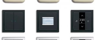
Types of devices
The model range of blocks is varied, it is always possible to find a product that matches the interior of the room. Such devices may differ in functionality.
According to this criterion they are divided into:
- Regular. Some of them have an indication, it indicates the location or the switched on key, they work in the dark;
- Walkthroughs. They are installed in a long corridor, on a staircase, etc. They are used to control lamps located in various places.
Note! When choosing, you must visually inspect the product. It should not have burrs, abrasions or damage. You should hear a click when switching keys.
The device has self-clamping lemmas. They are necessary for fixing and connecting wires. When the cores are pulled out (which is strictly prohibited), the special latches-clamps fail.
Features of the disassembly procedure
There are several types of switches, each of them has its own disassembly nuances. To successfully complete the task, you need to familiarize yourself with them.
- Triple switches are most often used in rooms with ceiling lighting, a large number of spotlights and other lighting fixtures. The peculiarity of such designs is thin keys. The dismantling process begins with their removal one by one. Most modern models are equipped with special holes for easy removal of elements.
To remove the dimmer, you must remove the rotary knob. - The process of dismantling a dimmer - a switch equipped with an adjustable rotary knob - does not have any fundamental differences. It is not the key that needs to be removed, but the control knob.
- The touch switch is disassembled by removing the outer panel. To do this, you can use an ordinary screwdriver or a special pick, which is often included in the kit. Care must be taken during work, otherwise the likelihood of glass damage increases.
- If the structure is double and the socket is paired with the switch, everything will have to be dismantled. Most often, the socket is removed first, since there is one of the mounting bolts under it.
Pass-through switches have a similar design. The only difference is the number of wires, since they are connected simultaneously in several places remote from each other.
Connection features
There are many models of a three-key switch with a socket, but its connection remains the same. The unit should be connected in the same way as a single or double model. The power cable is connected to the input of the device itself, and the wires run from the contact of the block with the switch to the light bulbs. Their number must match the device keys.
Basically, the socket is equipped with a separate neutral wire and, according to the diagram, is not connected to the switch, but they have a common “phase”. All “zeros” from the lamps and the socket itself are connected to the junction box. The “phase” is connected to a common contact included in the switch. The lighting wires are placed on separate blocks. It is from them that the voltage is transmitted to the light bulbs. At the ends of the cores, approximately 10 mm of insulation is removed. Since the contacts are tightened with clamps, and the wire can break, such devices will prevent this from happening.
NShVI - special lugs are used for connections
Basically, the switch block is mounted on the wall, in a special niche. For these purposes, calipers or spacer legs are used, and a decorated frame is put on top.
Usually a switch with keys and a socket is installed near the door of the room. The block helps to change the lighting and connect various household appliances used in the bathroom or toilet.
The distribution box has 5 connections. The ground wire should always go to the outlet. If the lamp has metal parts, then it is necessary to protect against electric shock. There is a special screw connection for this purpose.
Combined devices
Combined type of device The combined type of switches was not familiar to electricians until the mid-twentieth century. The current way to control light sources was a single-key switch. Two identical products were placed side by side. A little later, manufacturers released two-key switches for controlling individual groups of chandelier lamps.
A three-key switch combined with a socket appeared on the territory of the Russian Federation during the period of development of the construction of panel houses. The devices were intended to turn on lights in the kitchen, bathroom and bathroom.
The socket was installed in the bathroom for ease of use of a hairdryer and electric razor. After the popularization of washing machines, they began to be connected to a combi-appliance with or without grounding.
Double design for kitchen use
In modern high-rise buildings, double structures are used for kitchens, bathrooms and living spaces. The reason lies in European standards, according to which:
- switches are located at a height of 160 cm from the floor;
- sockets are installed at a height of 30-90 cm from the floor.
This connection allows you to place the switches at eye level for ease of use and furniture placement. Removing the socket allows you to conveniently turn off the lighting without changing the position of your hand.
Low-mounted socket groups in the bedroom are convenient in terms of masking wires. In the kitchen, they are placed above the work table and serve to illuminate the food preparation area and connect household appliances. In studio apartments, general and local light is used as a method of zoning space.
Connection methods
There are two main schemes for connecting a three-key switch, and in one, a distribution box is required (for twisting the wires), and in the other, the connection is located in the switch block. Let's consider each scheme separately.
With junction box
How to properly connect a three-key switch with a socket in this case? The basic rules that must be followed are as follows:
- they dismantle the old unit, after which 5 wires stick out from the wall;
- turn off the current;
- straighten all the wiring, supply power;
- using the indicator, find the “phase” (L), which is located on only one core;
- looking for “zero” (N);
- both wires are connected to the socket, with L going to the contact that goes to the switch jumper, and N to the free one;
- the other 3 wires are connected to the remaining contacts;
- When you switch keys, the lights should light up.
The connection diagram for a three-key switch using a junction box looks like this
On a note. Dismantling involves removing the old switch, cleaning the niche and wires, and checking the wiring. Only after this they begin to install the new device.
Before starting work, it is first determined whether N or L breaks in the room using a switch. Basically, this should be a “phase”. If this is not the case, then “L” goes from the junction box to the luminaire. That is why “zero” is supplied from the switches. In this incorrect version, N and L are swapped in the socket with the switch block.
Without junction box
Let's look at how to connect a block with an outlet directly. When dismantling the old unit, 8 wires will appear from the wall. If they are the same color, then proceed as follows:
- de-energize the line;
- carefully straighten the wires and make sure that the bare ends do not touch;
- they find a two-core wire (from it power is supplied to the unit and to the lighting), for this, voltage is applied and the “phase” is determined with an indicator;
- de-energize the line and mark the found wire (you can use electrical tape);
- looking for “zero”;
- 6 two-core wires stick out from the wall, which are necessary for three lamps (kitchen, bathroom, toilet);
- each has its own “phase” and “zero”;
- one core is taken from each of them and connected to N coming from the junction box;
- “zero” is applied to the socket contact from this connection (it does not have a jumper);
- N is connected to the socket and goes to all lamps;
- the found L coming from the shield is connected to the socket (second contact);
- other wires going to the lamps are connected to 3 contacts (switch block).
Important! This scheme has a drawback: twisted “neutral” conductors, which must be hidden in the switch block with the socket.
Connecting a three-button switch with a socket
Well, now let’s complicate the task a little: you need to connect a unit that combines both a three-key switch and a power outlet.
There is no need to worry - nothing supernatural awaits us. Let's say even more - we will not talk about any real difficulties, but rather about the design and connection features of such a product.
Main design features and connection diagrams
And there are only two such features, and they precisely determine those small differences from everything that was discussed above.
- The first feature is that since the block includes a power socket, then, unlike a conventional switch, it must also come with a “full set” of conductors. That is, phase L, neutral (zero) N, and if the socket has grounding contacts, the protective conductor PE.
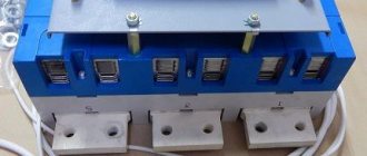
Let's take a look at the device and connection diagram of such a block.
Most of the blocks under consideration are arranged according to this principle.
1 – block body, which is also an installation box.
2 – power socket.
3 – terminal for connecting the phase conductor to the socket.
4 – terminal for connecting the neutral conductor to the socket
5 – terminal for connecting the PE protective conductor to the grounding contacts of the socket.
6 – three-key switch included in the block.
7 – terminal for connecting the common phase coming to the switch.
8 – jumper connecting the phase terminal of the socket with the common phase terminal of the switch. As a rule, it is already installed during the production of the block, but it still doesn’t hurt to check its presence.
9 – “mechanics” of a three-key switch.
10 – three terminals of the output vases – L1, L2 and L3.
That's all the features of the device.
The connection diagram is also very simple:
That’s all the “huge difference” in the circuit diagram of connecting the three-key switch unit and the power socket.
So, both phase and neutral are connected to the socket, and, if necessary, a protective conductor. But the last two end here; they do not take any part in the operation of the switch. And from the socket phase terminal through a jumper, phase L is transferred to the common input. Further - everything without any changes.
It remains to figure out which wires are best to be brought here when installing from scratch, that is, with wiring. The following option seems optimal: two three-core cables are laid:
- VVG 3×2.5, going from the distribution board to the outlet. For a power outlet, just in case, it is better to increase the cross-section of the conductor, which is why we are talking about 2.5 mm².
- VVG 3×1.5 - for three outgoing phases going from the switch to the distribution box.
We have already mentioned the jumper - it would be useful to check that it is in place and is well clamped into the terminals.
Expert opinion: Afanasyev E.V.
Chief editor of the Stroyday.ru project. Engineer.
Important: The phase must arrive exactly at the socket, and only then, through a jumper, go to the common phase input of the three-key switch. Unfortunately, some people claim and even do otherwise. You cannot install an extra “weak link” in the form of a jumper in the power outlet circuit, the cross-section of which is clearly not 2.5 mm²! But for lighting this is not a problem; there are no large currents in this circuit.
- The second feature is purely technological and has nothing to do with the electrical part. We are talking about the size and shape of such a block, which can no longer be installed in a standard round socket box.
The same block from several angles - to make its shape and features of mounting in the wall clearer.
As a rule, each of these blocks is equipped with its own mounting box, rectangular (with slightly rounded corners) in direct projection. That is, the whole difficulty is to cut out the necessary window in the wall to place and secure this box, and also to make holes in its body for inserting wires. Yes, there will be a little more fuss than with a regular socket box, the window for which is quickly cut out with one cutter, but nothing too bad either.
* * * * * * *
There probably won’t be any additions to the electrical installation - what was described and shown above should be quite sufficient. Including in matters of testing old wires - we, as already mentioned, got a little ahead of ourselves there, and, in fact, there is nothing to add.
We can only summarize it this way: the input of this block is connected like an ordinary socket, and the output is switched like a normal three-key switch.
You can complete the publication with a short video in which the master shares his experience of installing a three-key switch with a socket:
Installation errors
Many people wonder how to connect a three-key switch with a socket so that the work is done efficiently and everything functions correctly. Often, when connecting the socket unit with the switch, something goes wrong, and as a result, the chandelier does not light up.
Let's look at the errors that may occur when connecting devices:
- The socket works, but the switch does not. If you confuse “phase” and “zero”, then this will happen. That is, L is connected to the common line of the switch with a jumper instead of N. To correct the situation, you need to check everything with an indicator and redo it;
- When installing unit connections or replacing an old one, check the voltage in the wires. Often, electricians install separate wiring for the device, and there are two power supplies at the same time. Therefore, by assembling a sample according to the circuit, a short circuit is often created;
- Two keys do not work until the third is pressed. This means that the “phase” was connected incorrectly. Instead of the general input, it is connected to the output of the third key. To correct the indicator, you need to check the voltage of the contacts. If it lights up in all cases, it means that the switch breaks the “zero”, that is, someone crossed the wires in the panel. To correct this, unscrew the light bulbs and check the “phase” conductors. They find “zero” (common) and transfer it to the central contact of the three-key switch;
- Electricians do not recommend leaving the socket device in the block connected through one key, although this is convenient, since when pressed the light disappears. This is explained by the fact that various household appliances are often connected to the outlet, for example, a hair dryer from 1.5 to 2 kW. Extensions or tees can also be connected here. The device contacts are not designed for this voltage. In the best case, the unit will turn off and stop working, in the worst case, a fire will occur.
How to remove a switch from the wall?
Light switches, as a rule, have a significant operating reserve, so they do not have to be disassembled regularly.
What kind of lighting do you prefer?
Built-in Chandelier
However, if such a need does arise, then this should be done extremely carefully, and strictly following the sequence, so as not to damage the inside of the device, which is almost 90% plastic.
How to remove keys from a switch
The first thing you should always do is, of course, turn off the electricity and only then start working. You will need the following tools:
Using a flat-head screwdriver, you need to remove the switch keys, for which we install its tip between the frame and one of the keys, on the top or bottom side.
With a little force and using a screwdriver as a lever, you need to pry up the key and use your fingers to remove it from the grooves. The second key can be removed without the help of a screwdriver.
Using the indicator, they verify that there is no voltage; to do this, be sure to apply a screwdriver to each of the contacts. If the switch is located in a dark place, use a light source to avoid damaging the equipment.
After removing the keys with the switch, you can perform any operations, even under voltage, naturally, observing the necessary precautions. They check the integrity of the contacts and the presence of voltage on them, after which they make a conclusion about the operability of the device.
How to remove the frame from the switch
When there is a need to dismantle the switch for a more detailed inspection with disconnection from the network, or there is complete confidence that the device needs to be replaced, then it is necessary to remove not only the keys, but also the retaining frame, which in turn holds the decorative frame.
To do this, you will need the same set of tools as in the previous case, however, if the switch is secured with Phillips screws, then you will also need a Phillips screwdriver.
The fixing frame is located immediately under the keys, and can be removed using the same flat-head screwdriver.
It is held with latches on the switch body, so you need to pry the teeth with a screwdriver without unnecessary effort, since the frame is quite fragile, and pull it towards you with your fingers. At the same time, it is necessary to hold the frame, since without a frame it can easily fall down.
How to remove a socket with a switch
Nowadays, quite often you can find a universal electrical installation design - a socket and a switch in one housing. This is very convenient, as it allows you to power an outlet from one incoming line, and immediately connect lighting fixtures by running the phase wire through the switch.
How to disassemble a switch (one-key, two-key, with indicator)
In a modern apartment, a switch is not only a switching device, but also an interior detail, part of the apartment’s design. The need for dismantling and installation arises in the following cases:
Expert opinion
It-Technology, Electrical power and electronics specialist
Ask questions to the “Specialist for modernization of energy generation systems”
How to remove a switch from the wall? The first thing you need to do is remove the switch key by prying it up with a flat-head screwdriver, then unscrew the screws holding the housing that are located under it, as well as the screw on the socket. Ask, I'm in touch!
Manufacturers
Basically, the consumer makes a choice in favor of an aesthetic model; it all depends on the interior design of the apartment. If the design is “antique”, then the choice should be made on models from Fede.
The Gira triple switch with socket has an elegant design and is in great demand. Legrand models are perfect for any interior, as they have horizontal and vertical designs.
ABB supplies the market with a large range of switch units with LED socket outlets. They add functionality to aesthetics.
The Russian one produces combined models. You can find a single block made of plastic with vertical installation. Models with triple switches and a socket are available: without a grounding contact, with red backlight or with a Euro socket with protective curtains.
Important! All switches have a voltage of 220 V, and the rated load ranges from 10 to 16 A.
The buyer decides which manufacturer of switch to choose.
This is how you install a three-key switch with a socket yourself. If you have no experience in this matter, it is better to contact a specialist. He will not only do everything quickly, but will also help you choose the best devices, advise where to install them, and check all the electrical equipment in the apartment.
Video
The three-key light switch is designed to control three lighting circuits. Moreover, each circuit can have any number of light bulbs - one, two, three or more.
The connection must begin by connecting the wires to the switch in the installation box. And to do this, you first need to disassemble it.
Video selection of other masters
A light switch is a switching device that performs two functions: it opens the electrical circuit and supplies voltage to the lamp. Such switches are designed only for household electrical wiring and will not turn off high currents and short circuits.
Their management in apartments can be as follows:
- pressing a key;
- button activation;
- toggle switch switching;
- using a sensor;
- remote control;
- tension and release of the chain.
Interesting.
In addition, switches are an element of decor in the apartment.
Connecting wires to the switch
Remove the keys from the switch. You need to start from the central one. There is usually a gap underneath it. Insert the tip of a screwdriver into it and, with a little force, snap off the key.
The rest can be removed by hand without using a screwdriver.
Next, on the sides, again using a screwdriver, pry up the latches and release the decorative trim.
The central part of the switch with 4 contacts should remain. One on top and three on bottom.
The top contact may not always be centered, keep this in mind.
This single terminal must receive the common phase power conductor from the distribution box.
The bottom three are connected to the wires going to the light bulbs, that is, to separate circuits No. 1, No. 2, No. 3.
To connect you will need a 4-core cable VVGnG-Ls 4*1.5mm2. From the junction box in the groove, lower it into the socket box where the switch should be mounted. Then you start connecting the wires.
Connect the phase conductor to the common central terminal.
Connect the remaining three wires to the outgoing circuits to the lower terminals. In order not to get confused in the future, it is better to label them.
Insert the switch into the mounting box and secure it there. Place the keys in reverse order, starting with the outermost ones. You simply snap them back into place.
In doing so, pay attention to the location of the keys.
The correct position is when the lighting turns on when the key is pressed up, and turns off when the key is pressed down.
Now you need to correctly connect all the wires in the junction box.
Several cables can come into the junction box.
Firstly, this is a three-wire power cable from the lighting circuit breaker installed in the electrical panel. Secondly, a 4-wire cable goes down to the three-key switch, which you have already connected from below.
Well, then there may be options. If you have one chandelier with 3, 6, 9 bulbs, then you can connect it with one single five or 4-core VVGnG-Ls cable with a cross-section of 1.5 mm2.
If you have three independent lamps, in different parts of the room or house, then you will have to run a separate 3-core cable to each of them. Let's consider the last option in more detail.
Wire connections in the distribution box
So, in the junction box you will have 5 cables. You need to avoid getting confused and correctly connect their wires to each other.
To do this, always start the connection with the neutral and grounding conductors. Regardless of the number of circuits and light bulbs, all zeros must be combined into one common point.
The same applies to grounding conductors. On lamps they are connected to the housing. Although in some cases they may not exist at all.
The fastest way to connect the cores is through Vago terminal clamps. For lighting loads this is a very good option.
Try to choose the colors of the cores in accordance with the current rules. Zeros are blue conductors, groundings are yellow-green.
Pay special attention to the fact that the zero does not go to the switch, but goes directly to the lamps. Only the phase should be broken through the contacts of the three-key switch.
It remains to connect the phase conductors. You need to start with the phase coming through the cable from the input machine.
You connect it only to the common phase conductor going to the central terminal of the three-key switch and nowhere else. This will trigger the phase on the switch.
Next, connect the three wires coming out of the keys with the three phase wires of the outgoing circuits to the lamps. You do this with three different wago clamps.
If you have previously marked the wires, you can easily recognize which key will turn off which light bulb (toilet, bathroom, hallway, etc.)
If assembled correctly, the distribution box should have 6 connection points.
Before directly applying voltage, you must once again check the entire connection diagram of the 3-key switch. If there are no errors, then turn on the automatic lighting and use the keys to start your lamps.
Options for replacing the switch yourself
At home, single-key and two-key switches are used. The process of replacing them differs in the number of wires. Before installation, it is recommended to check the cables themselves and the integrity of the insulation.
If any violations are detected, you should call an electrician to further replace the electrical wiring section.
Change with one button (single-key)
The insulation at the ends of the cables should be stripped. The conductors are then connected to the switch terminals - the phase contact (red) is connected to L1, blue or black to L2. The switch is installed in the socket. The housing is fixed with screws.
Electricity is supplied to the distribution panel and functionality is checked. If everything is done correctly, you can install the decorative cover.
Replacing a two-key
A device with two buttons requires connecting three phase conductors to terminal L3 and two conductors to L1 and L2. If a three-key switch is used, then 4 conductors are used - a phase and three contacts for different groups of lamps.
In a modern apartment, a switch is not only a switching device, but also an interior detail, part of the apartment’s design. The need for dismantling and installation arises in the following cases:
- when laying electrical wiring in a new house (apartment);
- to replace outdated models with new ones;
- to connect an additional light source;
- when replacing a single-key light switch with a two-key one;
- when arranging furniture (sometimes by an offensive five to ten centimeters).
Despite the difference in goals, the technology and sequence of actions are the same in all cases.
Expert opinion
It-Technology, Electrical power and electronics specialist
Ask questions to the “Specialist for modernization of energy generation systems”
Is the switch really the cause? If not, then look at the input machine, maybe you exceeded the permissible load by turning on the electric kettle, iron and microwave oven at the same time, and it turned off. Ask, I'm in touch!
Connecting a 3-key switch and socket
Often, a triple switch is installed in the same block with a socket. How to make this connection correctly?
First of all, you should know that for such installation it is already necessary to use a copper cable with a cross-section of 2.5 mm2.
A cable of this cross-section should go not only from the distribution box to the switch, but most importantly from the switchboard, to this very junction box.
Run the 5*2.5mm2 cable down the groove to the switch+socket block. Now it will be necessary to set not only a phase, but also a zero. It is better to connect the common phase conductor to the contact of the socket, since it is on it that the load is greater than on the lamps.
And then, using a jumper, connect this phase to the upper terminal of the 3-key switch.
Zero is connected to the second contact of the socket. The remaining three wires, according to the previously discussed diagram, are routed under the three lower contacts of the three-key switch.
The wiring in the junction box is carried out almost similarly to that discussed above. Except that it is necessary to connect another neutral wire to the common zero point.
1The most common mistake is that the socket works, but the switch does not.
The point here may be that you simply mixed up the phase and neutral on the outlet. And accordingly, they connected the jumper to the common terminal of the switch not with the phase wire, but with the neutral wire.
Using an indicator screwdriver, double-check where the phase is coming from.
2If you are not installing a socket-switch unit in a new location, but are replacing an existing one, be sure to check the supply voltage on all wires.
Often, some electricians run separate wiring for the outlet and separate wiring for the switch. As a result, you may have two power supplies in the unit at the same time. And by assembling the circuit according to the above instructions, you can inadvertently create a short circuit.
3The light on two keys does not light up until you turn on the third.
As soon as you turn it on, everything works as it should. It's all about incorrect phase connection. You launched it on the output contact of the third key, and not on the general input. Again, everything is decided by checking the indicator.
4 Most often, problems arise when replacing old switch-socket units and old three-key switches with new ones.
You start checking the voltage on the contacts, and the indicator screwdriver shows three incoming phases instead of one! That is, it lights up on all three contacts at the same time. How is this possible?
But the fact is that the switch in this case does not break the phase, but the zero!
The electrician who directly connected the old switch himself a long time ago may not be at fault. It’s just that over time, someone else transferred the wires in the meter or the common switchboard to your apartment.
So it turned out that where there was a phase before, a zero was formed. Often, understanding switchboards is not easy even for the installers themselves.
The indicator lights up on the contacts because the bulbs are screwed into the sockets. As a result, the circuit turns out to be closed through the filament.
Unscrew all the lamps and check the phase conductors again. The glow in the three phases should disappear. For the correct connection, here you already need to find a common zero and throw it onto the central contact of the new three-key switch.
The best way is to find the cause in the switchboard, inviting a professional electrician and restoring the normal power supply circuit.
5Try never to connect a socket in the unit through one of the keys.
Many people find it convenient to press a key and the light in the socket goes out. This is not recommended. This is due to the fact that usually a powerful load is connected through the socket contacts, for example a 1.5-2 kW hair dryer.
But you can still connect a tee or extension cable through it! The switch contacts are not designed for a current of this magnitude and duration. As a result, after some time, the voltage in the entire unit will disappear, unless a fire occurs even earlier.
Sources - Kabel.RF
Wiring through junction box
It is better to use the same one fine to bring all three phase wires to the distribution box again, and then use the common upper fine to bring them to the lamps. If we are doing wiring to a chandelier, then the last option is the best.
Triple switch: connection diagram to the chandelier
L – phase to the switch (red); then the phase (yellow, brown, pink) goes to three groups of chandelier lamps; N – working zero (blue), goes directly to the chandelier and is separated by the chandelier terminal block into groups; PE – grounding (yellow-green), connected to the chandelier body
Thus, before connecting the triple switch, it is necessary to prepare all the wiring.
All work should be carried out with the lighting circuit switched off. To search for zero and phase, the power is turned on, but after the indicator finds them and marks them, it turns off again.
Next, the following work is performed:
- Search for existing wiring: you need to find the junction box, the fines that will be involved in the wiring. It is necessary to mark the walls for treatment. A place is marked for the hole where the three-key switch will be installed, and for routing the wiring to and from it.
- Opening existing channels and punching new ones.
- Laying and securing cables from the box to the installation site. The wires for phase, neutral and ground (if any) must be marked. If possible, you should adhere to the standard colors of the wires: blue for neutral, yellow-green for grounding and other colors for the phase.
- Installation and fastening of socket boxes. The wires are routed inside them.
Connecting a triple switch
Identifying the wires in the junction box to which the wiring should be connected. Phase and zero are indicated by the indicator. They are marked (with electrical tape).
This work is carried out after inspection has confirmed that the previous actions did not cause damage to the wiring. After this, the lighting circuit breaker is turned on and the phase phase of the distribution box wires to which the connection must be made is determined. The wires are marked, after which the power is turned off again.
The wires of the new wiring are connected to the junction box, their ends are securely insulated with special caps.
To check the correct connection, turn on the machine again and, making sure that everything is normal, check the phase on all wires. It should be located on only one phase wire going through the socket to the switch. The rest should have zero: on the neutral wires going to the lamps, on the ground wires and phase wires going from the switch to the lamps, since they are open.
- Having turned off the machine again, you can connect the switch by connecting the wires to the terminals according to the connection diagram. After this, the switch can be put in its place, secured in the socket box according to the design.
- The wires are connected to the lamp sockets or terminal blocks of the chandelier. Each cartridge must have two wires - zero and open phase.
Before connecting each wire to a chandelier or lamp, you need to know exactly which of them are zero (coming from the junction box, blue according to the norm) and which are phase. Color identification of each wire helps. But in order for them to connect correctly, you need to turn on the machine to determine it and check each of them in turn with an indicator, including the corresponding button of the three-button switch.
After installation and checking that all lamp units are connected, the work can be considered complete.