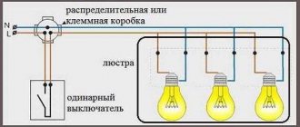
Electrical wiring of any room, be it a huge country house or a small outbuilding (basement, garage, country house), includes three main elements - a switch, a socket and a light bulb. While they remain relevant always and everywhere. During repairs, construction or redevelopment, you will definitely encounter them. Therefore, basic knowledge of electrical engineering will not be superfluous - what is the connection diagram for a switch and socket, how does it work and what materials and tools will be required for its installation?
Below are detailed step-by-step instructions, with the guidance of which even a not very experienced electrician will be able to install sockets and switches with his own hands.
Connecting a switch from an outlet
Quite often the question arises of how to connect an outlet and a switch located close to each other. To do this, pulling a separate wire from the distribution board is not always rational, and why would it be necessary if the connection can be made using existing wires?
There are two methods of such connection, which do not differ much in relation to each other.
Connecting a switch from an outlet for a lamp located nearby
Before connecting the socket and switch, you should decide on the location of the lamp that will turn on the switch. If it is located close to the switch, for example, it is a sconce not far from the wall, then it is advisable to connect the neutral wire directly from the outlet.
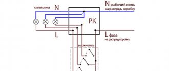
Connection diagram for a switch with a socket using the “zero” socket
- In this case, connecting the socket with a switch looks like this. First, according to the sequence given above, the socket is connected.
- Now we make the connection on our lamp. We connect its neutral and protective wire to the neutral and protective wire of the socket. It is advisable to do this directly at the socket terminals.
- We connect the phase wire from the lamp to the switch terminal.
- Now we connect the phase wire to the socket terminal and to the switch input and our circuit is ready for operation.
Connecting a switch from an outlet for a lamp located far away
If it is necessary to connect a switch with a socket for a lamp located far from the switch, then it is advisable to use another method. Fundamentally, it does not differ from that described above, but it allows you to save the number of wires.
Connecting a switch using only the socket phase
- In this case, we again, without any changes, consistently perform the operations of connecting the outlet.
- At the next stage, we connect the wires to our lamp. Then we connect the neutral and protective wires to the corresponding wires in the nearest junction box.
- We connect the phase wire from the lamp to the switch terminal.
- Now we connect the phase wire to the input of the switch and the phase wire of the socket and we can check the functionality of our circuit.
Scheme for connecting a circuit breaker device through a socket
In order to connect a switch using a socket, a standard connection diagram is used
Important! There is always a break in the phase conductor in the breaker, and the zero goes directly to the light source:
- A distribution box is installed into which wires are fed from the existing outlet (the room must first be de-energized), wires going to the switch, and a wire from the lamp.
- We connect one core from the source of electricity consumption to zero, the phase must be connected to the switch; if it goes through the junction box, then it is connected to the core from the switch.
In the presented diagram, the phase wire goes from the light bulb directly to the breaker; when it is in the “on” position, electricity is consumed; when in the “off” position, the load does not receive electricity.
How to choose the wire cross-section?
Often the electrical connection of a source of energy consumption, for example, a sconce from an outlet, occurs to install additional lighting, in our case it can be one or more sconces, for this reason the current is low and it is possible to select wires of the desired cross-section, but there are nuances:
- according to safety requirements and PUE, for these purposes it is impossible to use a wire with a copper conductor cross-section of less than one square millimeter;
- and a wire with an aluminum core of at least two and a half square millimeters.
When choosing a wire, you need to take into account how it is laid, so there are certain conditions for open laying:
- for a copper wire, the minimum cross-section is 1.5 square millimeters;
- The minimum value of an aluminum core is 4.0 square millimeters.
To lay a wire along the outer wall of a house or building, there are the following requirements:
- for wires with copper conductors - 2.5 square millimeters;
- for aluminum wire cores - 4.0 square millimeters.
How to independently connect a light source from a switch?
One of the simple ways, according to experts, is to connect the sconce to the circuit through a switch powered by an outlet using neutral and phase wires; this is especially beneficial when the lamp is located close to the switch.
To complete this work you need to do the following:
- Carry out installation work to install the lighting source and switch, then carry out the steps to connect them.
- From the socket from which we will connect our voltage breaker, we remove the voltage using a machine in the panel (usually the wiring is carried out according to consumption groups), and check with a “probe” for the absence of a phase.
- Open the socket; if the work on its connection is carried out with a copper wire with a color difference, then:
- zero – blue wire;
- grounding – second wire with double color (yellow-green);
- phase is the third wire, it may be brown.
If there is no color difference and the connection is made with an aluminum wire, you need to briefly apply voltage to the socket and use a “probe” to determine the phase of the electrically conductive wire.
- We connect the wire from the switch (to its input), which is already connected to the breaker, to the socket phase, and connect the wire from the lamp to the output from the switch.
- When you don't know how to connect a double switch, the solution is the same, but from the output of the electrical circuit interrupter, each phase wire goes to its own light source, or for a chandelier to its own power consumption bulbs.
- To the neutral wire of the socket we connect the neutral wire of the switch to the light bulb; if the socket has a grounding wire, we connect it to the grounding wire from the lighting source.
- After this, the wiring is laid and all connections are insulated, as well as the assembled circuit is tested.
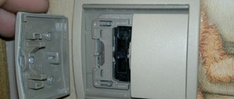
How to connect a socket-switch, which is assembled in a single housing?
When there is an outlet in the bedroom or in another area of the room, and you want to install a sconce or floor lamp, you can use a socket-switch device, which is assembled in a single housing, this is done as follows:
- the socket has a standard connection, phase and zero; in new buildings, euro sockets are connected with a grounding wire;
- the phase is supplied to the input of the breaker (switch), and from its output the wire goes to the lamp;
- The other two wires (the neutral wire and the ground wire) are connected directly to the lamp.
It is necessary to understand that you cannot make the reverse connection, in other words, connect the socket from the switch; it can only receive electricity from the circuit breaker in the switchboard of the house or apartment.
Installation of an apartment or house electrical network
Before considering the issues of making changes to the existing network, let's understand how it works. After all, your ability to make changes to it directly depends on your understanding of this issue.
Main diagram of the apartment electrical network
First of all, let's determine how the wiring diagram for an apartment or house is made. This circuit begins in the input panel.
The photo shows a possible diagram of an apartment electrical network
- So, let's start with the introductory panel. It can be located in the entrance or directly in the apartment. In it you will find an input circuit breaker, which receives a power cable from the general house electrical network. Sometimes instead of a machine there are batch switches or even circuit breakers, but this is mainly in old houses.
- From the input circuit breaker the wires go to the meter, and from it to the group circuit breakers. Usually there are two or more of these groups. This amount directly depends on the possible loads in your apartment.
- Group circuit breakers divide the electrical network of your apartment or house into several groups that are not connected to each other. Groups can be formed according to the nature of the loads or the ease of installation. This is not a fundamental question. The only thing that the instructions prescribe is the division into different groups of electrical appliances in the bathroom and kitchen with electrical appliances in the living rooms.
- From group circuit breakers, wires go to one, two or more distribution boxes. They are directly connected to a group network of sockets and switches. This concentration of connections in one place makes it possible to simplify maintenance as much as possible and hide utility networks.
Connecting switches and sockets
In order to determine whether it is possible to connect an outlet from a switch, let's look at the features of their connection to the group supply wire. After all, starting from this, we can clearly imagine our future scheme.
Connecting the socket
- To connect the socket in accordance with clause 7.1.13 of the PUE, three wires are required. One of them is phase, the second is neutral and the third is protective grounding. These wires, in accordance with clause 1.1.30 of the PUE, must be marked with blue as the neutral wire, yellow-green as the protective grounding wire and any other color as the phase wire.
- The phase and neutral wires from the supply group wire in the distribution box are connected to the power contacts of the socket. Protective grounding to grounding contacts.
Switch connection
- Connecting the switch is even easier to do yourself. After all, this requires only two wires. Moreover, both of them will be phase. The first wire is connected to the phase conductor of the group line and to the switch input.
- The second wire from the switch output goes to the distribution box, where it is connected to the phase wire of the lamp. The zero of the lamp is connected bypassing the switch, directly in the distribution box to the supply wire.
Recommended wires for boxless wiring
Conductors with 4-6 mm2 conductors were laid between the distribution boxes, and taps were made from it for individual sockets and lighting fixtures with thinner wires. The common wire was designed for the load of all consumers in the group. In our version, a cross-section of 4-6mm2 will not be very convenient for connecting to contacts and packaging in socket boxes.
Such wires are rigid, difficult to clamp with bolted connections of the contacts, sometimes the terminals even break. It is very convenient to use 2.5 mm2 copper wire, it is elastic and fits perfectly into the terminal grooves. The current loads that the cores can withstand can be seen in the table. Based on this, make calculations on the number of sockets in the group and the power of connected household appliances.
| cross-sections of copper conductor for various current loads | ||||||||||||||
| Current in A | 1 | 2 | 3 | 4 | 5 | 6 | 10 | 16 | 20 | 25 | 32 | 40 | 50 | 63 |
| S - in mm2 | 0,17 | 0,33 | 0,52 | 0,67 | 0,84 | 1 | 1,7 | 2,7 | 3,3 | 4,2 | 5,3 | 6,7 | 8,4 | 10,5 |
| Ø in mm | 0,45 | 0,65 | 0,81 | 0,92 | 1,02 | 1,13 | 1,45 | 1,87 | 2,05 | 2,32 | 2,60 | 2,92 | 3,27 | 3,66 |
Based on the calculated values, a 2.5 mm2 wire can withstand a load of up to 16A. Data have been collected on the approximate powers and currents consumed by household appliances for various purposes. Using this information, you can guess how many and what devices to include in the outlet group.
| Type of household appliances | power in W | current in Amperes |
| Old style incandescent lamps | 60 – 250 | 0,3 – 1 |
| Small-sized heating appliances: teapots, coffee pots and boilers | 1000 – 2000 | 5,5 – 10 |
| Stationary and portable electric stoves | 1000 – 6000 | 6 – 55 |
| Microwaves of various brands | 1500 – 2200 | 8 – 10,5 |
| Kitchen electric meat grinders for non-industrial purposes, for home use. | 1500 – 2200 | 8 – 10,5 |
| Toasters for baking bread | 500 – 1500 | 2,5 – 8 |
| Equipment for preparing grilled dishes | 1200 – 2000 | 7,5 – 8 |
| Blenders and mixers | 500 – 1500 | 2,5 – 9 |
| Food processors | 500 – 1500 | 2,5 – 9 |
| Electric oven | 1000 – 2000 | 5,5 – 8 |
| dishwashing machines | 1000 – 2000 | 5,5 – 8 |
| Household washing machines | 1200 – 2000 | 5.5 – 8 |
| Electric shoe or clothes dryers | 2000 – 3000 | 8 – 12 |
| Irons for non-industrial use | 1200 – 2000 | 5.5 – 8 |
| Floor and portable vacuum cleaners | 800 – 2000 | 3.5 – 8 |
| Spiral heaters | 500 – 3000 | 1.8 – 12 |
| Hand-held hair dryers | 500 – 1500 | 1.5 – 7 |
| Split systems and air conditioners | 1000 – 3000 | 6 – 12 |
| computers | 300 – 800 | 0.8 – 3,2 |
| Hand-held power tools (grinder, drill, hammer drills, jigsaw, etc.) | 500 – 2500 | 1.8 – 12 |
For lighting devices, it is recommended to lay a three-wire cable from 0.7 to 1 mm2. Practice shows that this is quite enough, especially when LED lamps and energy-saving lamps are used.
A typical example of combining a socket and a switch in one unit
Often in a corridor or hallway there is a need to combine a network connection point (socket) and a switch for several lighting groups. This method solves several problems:
- An extensive electrical outlet network in the corridor is usually not needed: there are no constantly used electrical appliances. However, there is a need to connect a vacuum cleaner or charger. In addition, a radiotelephone base unit can be installed in the hallway.
- There is little space on the walls in this room; there are wardrobes, a mirror, and a hanger. Part of the corridor is usually occupied by the input switchboard and metering device (meter). Therefore, compact placement of switching equipment is a key issue.
- By combining the socket and switch, wiring is saved and installation of an additional junction box is not required.
- If you additionally connect a second device: a switch to a socket, or vice versa, there is no need to damage the wall or organize a route for the power cable. The connection is made with minimal impact on the room.
As can be seen in the illustration, to implement the entire circuit you will need one circuit breaker (in the panel it can be called “corridor: lighting, socket”), and one distribution box.
The zero bus N (blue color) passes through a kind of transit to the lighting groups and to the socket. The PE grounding is inserted into the socket body, and (if one of the lighting groups is in the bathroom) into the lamp body. The phase after the machine is connected to the socket through the distribution box. The disconnection occurs in the socket box. In this case, any terminal block is used: for example, WAGO.
A small section of wire connects the phase terminal in the socket and the input terminal of the two-key switch. Next, a phase is laid from the output terminals to each lighting group.
This scheme is usually used during design, since you still have to lay cables to different lighting groups. If such a solution is optional, you do not install additional boxes. The hole for the switch or socket box is made next to the already mounted device. All that remains is to install additional wiring.
If there is a need to connect the socket and lighting to different circuit breakers (for example, a power socket is used for a powerful electrical appliance), the phase is initiated along different power lines.
There is no need to use an additional distribution box; the phase wire passes through it in transit, without disconnection.
In any case, this installation method saves both wiring and wall space. For example, let's look at the classic version of connecting a socket and switch to a distribution box.
Two cable routes were laid, the connection was in the junction box. Looking at the diagram, it becomes obvious that connecting the switch directly to the outlet is more efficient.
How to connect a single-key switch from an outlet
The classic option: a common zero bus from the distribution box is connected to a light point.
Grounding goes through the same cable channel (if used). But the phase wire does not go directly to the lighting fixture. A single-key switch (located in the same housing as the socket) breaks the circuit between the phase contact in the socket box and the light source. Quite a common scheme. Such a block can often be found in lighting stores.
Another application for such a module is a switchable socket. Let's say you have an electrical appliance that should be turned off at night or when leaving the room. This could be a router that distributes Wi-Fi. The unit itself is located high, so it is not always possible to use the standard power button. By clicking the switch key, you will de-energize the equipment without touching the circuit breaker in the distribution panel. Or, on the contrary: the device must be powered under certain conditions. For example, power supply for an alarm system.
In this case, the phase wire inside the block is simply opened by a switch, and the power wiring is connected as to a regular socket.
Connecting various electrical receivers in the junction box
Now you can directly examine the connection of the wires in the distribution box. After all, it largely depends on the type of device being connected, as well as on the number of these devices. Sometimes it is advisable to create two or even three distribution boxes for one room rather than trying to fit all the connections into one.
Connecting group wires
First of all, we need to determine whether we have an end or pass-through junction box. Ideally, each junction box should be an end box.
A terminal box is a junction box that does not have wires connecting it to other junction boxes. A pass-through is a box that has such a connection.
The end distribution box contains three cores of the power cable or wire from which the end consumers are powered.
- The feed-through junction box has three supply wires, which are usually connected to the terminal block. The next distribution box is powered from the same terminal block. As a result, we get two wires connected to each other.
- Another possible option is if for one group the box is an end box, and for another group it is a pass-through box. Moreover, usually the wire for which the box is a feedthrough does not have any connections in it. It just runs along the box.
Connecting sockets
First of all, let's look at the connection of wires in the junction box at home when connecting an outlet. After all, this is one of the simplest connections.
- So, in the junction box we have three strands of the supply wire. As we have already said, this is phase, zero and ground, indicated by the corresponding colors.
- To connect the socket, we need to connect the wire going directly to the socket to the corresponding cores of the power cable. In this case, color coding should be observed.
Switch connection
The wiring diagram in the junction box for connecting the switch is somewhat more complicated, but also quite simple and understandable. And even a two or three-key switch should not cause you problems.
- First of all, we connect the switch. To do this, it is necessary to connect the wire leading to the switch input to the phase of the supply cable. We lead the wire from the switch output into the distribution box.
- Now we connect the lamp. First of all, we connect it to the neutral and protective power cable, the wires going to the lamp. After this, we connect the phase wire of the lamp to the wire coming from the switch terminal.
- As for two-, three-, or even four-key switches, the same principle applies. The only difference is the connection of the phase wire from the switch terminal.
- If this is a chandelier with two operating modes, then it has two phase wires. We connect our outputs from the switch to them.
- If different lamps will be connected from the switch, then our instructions advise first of all to connect their neutral and phase wires. Then one phase wire from the switch terminals to each lamp.
Connecting the lamp and socket
But to connect an outlet with a switch there will be a more complex circuit. The connection of the wires in the junction box is a little more confusing in this case. But if you analyze the diagram completely, then there is nothing complicated in it.
- First of all, using the method described above, we connect the outlet.
- Now we connect the neutral and protective wires of the lamp. This is done in the same way as with a normal connection.
- As for the phase wire for the switch, there can be two options. You can purchase a single product, a switch with a socket in which the connection has already been made. Or you can purchase a separate switch and a separate socket. In this case, you will make the connection between them yourself.
- To avoid wastage of wires, in this case it is advisable to connect the switch directly from the phase contact of the socket. We connect this wire to the switch input.
- The wire from the switch output, as with a normal connection, is brought out into the junction box. Here we connect it to the phase wire of the lamp.
Connection diagram
The electrical circuit represents a parallel connection to the power source of a lighting fixture with a light bulb, a switch and a socket.
Preparatory work
After turning off the machine, you need to once again make sure that there is no voltage, now using an indicator screwdriver. First, check its working condition in an area that is known to be energized, for example, at the entrance to the machine. The indicator lights up after touching the phase, which means it is in good condition. Now touch the indicator screwdriver to the cores of the power wire, which is brought into the apartment from the machine; there should be no glow. This means that the tension has been relieved and work can begin.
Lay the wires in the grooves made, leading them to the wall holes. At the same time, leave the ends of 10-15 cm for cutting the cores, do not regret it, it is better to make a slightly larger reserve than to suffer later when connecting and connecting. Install a distribution box and socket boxes in the holes; use plaster or alabaster to securely fix them.
Electric installation work
Place a two-wire cable from the mains supply (phase and neutral) into the junction box. Three wires must be laid from the box: one to the switch, the second to the lamp, the third to the outlet.
For a wire whose cores have different insulation colors, red indicates phase, blue indicates zero.
The switch has an input and output contact; a phase conductor is connected to the input. Connect the second core to the output contact of the switch.
A two-wire wire must also be laid to the lamp. The lamp socket has two contacts. The central spring contact (phase) is used to directly supply voltage to the light bulb. The side contact in the socket is zero, the lamp will come into contact with it after screwing in with its base.
Another two-wire wire is laid from the junction box to the outlet. This switching device has a contact part consisting of two terminals to which phase and zero are connected.
The connection diagram for the switch, lamp and socket in the distribution box is as follows:
- Connect the neutral conductor from the supply wire with the neutral conductors going to the lamp and socket.
- Connect the phase conductor from the supply wire with the phase conductors going to the switch and socket.
- Connect the remaining core from the output contact of the switch to the phase core of the lamp.
All connections must be made as firmly as possible to ensure reliable contact. This can be done the old fashioned way - by twisting, which it is also advisable to solder on top. There are also more modern devices: special blocks (in which the wire is clamped under a screw) or PPE (connecting insulating clamps).
For more information about connecting wires in a junction box, watch this video:
Checking the circuit and completing the work
Move all the twists in different directions so that they do not touch each other and check the operation of the assembled circuit. Turn on the input circuit breaker for the apartment, thereby supplying voltage from the power source to the newly mounted distribution box. The switch is in the “off” position, the lamp does not light, which means everything is correct, the phase is open. Now press the switch key to the “on” position, the electrical circuit is closed and voltage is supplied through it from the power source to the lamp, the light bulb lights up. There will be constant voltage at the outlet; you can check its operation by connecting any electrical appliance. Plug the hair dryer, radio or electric kettle into the outlet and check its operation.
All that remains is to securely place the switch and socket in the socket boxes, secure them, and put protective covers on top. The distribution box is also covered with a lid; during any repair work, never hide it under wallpaper or plaster. Remember, the distribution box should always be accessible, no matter how much it spoils the overall appearance of your room.
Also keep in mind that if the lighting fixture and socket are structurally grounded, then their electrical circuit will require a three-core wire. The same wire of three cores should also come to the junction box from the power source. Typically, the grounding conductor is indicated in green or yellow; in the same way, in the box you will need to connect three protective grounding conductors into one twist - from the power source, socket and lamp.
Connecting the socket and switch
When connecting a socket and switch, just look at their connection diagrams and everything will fall into place. You should also consider the wiring diagrams for sockets with single, double and triple switches.
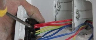
Usually, the problem of a person who just wants to replace the switch-socket unit is that he sees only a bundle of wires, which does not give him the overall picture, and therefore prevents him from correctly orienting himself. It may also be that the previous installation was made with incorrect phasing, which also does not add clarity. So enough words, let's figure it out.
Connection diagram for a socket with a single-key switch
The switch is turned off (zero comes to its input through the light bulb)
The switch is on (through it the phase is supplied to the light bulb)
As we can see from the diagram for connecting a socket with a switch, we need three wires: one is where the phase comes in, the other is zero, and the third is where the phase returns through a jumper to the input of the switch, powering the lamp bulb.
It should be noted that the first three pictures (top) are with the correct connection, that is, zero from the junction box goes directly to the lamp.
Then in the connection box for the socket and switch we see three wires. Two, on which there is a zero (we get one zero through the connected lamp), and the other with a phase. This is provided that a working lamp is connected.
When replacing a block, we can (after de-energizing the line) simply repeat the connection (by adding a similar block or socket with a switch). But, if this is not possible, we need to determine exactly where which wire is. To do this, having de-energized the line, we make a braid.
Photo of a three-wire braid.
It will help us avoid shorting the wires and will give us the opportunity, if necessary, to place the wires in the sequence we need.
Then we turn on the line and use the indicator to find the phase, through it (the phase) we determine the direct zero with a control light (the control light glows at full intensity), the zero and the phase are connected to the socket, the other wire through the switch (the phase is supplied by a jumper to the switch input) should power the lamp.
When you touch it (the remaining wire), the control lamp glows at the incandescent level, and the lamp lights up weakly (if an incandescent lamp is connected) or lights up at full power (modern lamps).
Having decided on the wires, we de-energize the line and connect the socket-switch unit. Once assembled, turn it on and check its functionality.
Connection diagram for a socket with a single-key switch with incorrect phasing
Incorrect phasing is easily determined by the fact that the indicator will show two wires with a phase. All actions remain the same as described above with the only difference being that now the direct phase is located (searched for) through zero, and it (zero) is supplied to the switch input through a jumper.
You may come across a situation where there are not three, but four wires, do not be alarmed, it means that one wire is either not working, or a pair is taken by the core (two wires are simply connected together). Just insulate the wire you don't need and that's it.
Connection diagram for a socket with a two-button switch
The switch is turned off (zero comes to its input through the light bulbs)
The switch is on (through it the phase is supplied to the light bulbs)
As you can see, everything is the same, only one more wire has been added. Don't forget about the braid.
Photo of a braid with four wires.
Connection diagram for a socket with a three-button switch
The switch is turned off (zero comes to its input through the light bulbs)
The switch is on (through it the phase is supplied to the light bulbs)
Photo of a five-wire braid.
The circuit does not become much more complicated when connecting a socket and a three-key switch, but if you have understood the previous circuits, then this one will not be difficult for you.
In practice, here, too, there may be not five, but six wires, but this means that the electrician simply did not want to separate one wire from the double one and one wire is either not working, or the pair is taken by the core.
How to connect a socket with a switch | Video explanation
That's all, good luck with your installation!
In the previous article, I talked about how single or double electrical sockets are connected to electrical wiring or to each other using a cable. Now I will tell you in detail how to correctly connect blocks consisting of a socket + light switch or three or four sockets.
Take it into account. that in one block under one cover not only switches, electrical sockets are combined, but also, if necessary, telephone and computer ones.
Before starting work on connecting electrical outlets, you must turn off the power supply automatically and make sure that there is no voltage using an indicator screwdriver.
Installation features
When carrying out repair work indoors to install additional lighting in order to save labor load (no need to groove the walls), you need to know that for laying wires there are diagrams for switching on the lighting device, which answer the question of how to connect a switch from an outlet, but also in In this case, all work has its own subtleties.
- All wires in the room must be laid only according to the diagram and in straight lines vertically or horizontally.
- In wooden houses, it is necessary to prevent their interaction with wooden walls during the laying of wires; the electrical wiring is laid through special insulators.
- Hidden wiring is carried out in houses made of stone or reinforced concrete slabs using grooves (channels) made in them.
During the repair process, two-core or three-core electrical wires are used, in which one conductor carries a phase, the other a zero, and if there are three conductors, then the third also carries grounding.
What material and tools are needed to carry out the work?
To carry out work on installing additional lighting in the room, you must have the following tools and consumables:
- a device with which you can de-energize an electrical circuit;
- electrical wiring of the same cross-section and design (aluminum or copper conductor), which is installed throughout the entire room, house or apartment;
- distribution boxes in which we make connections;
- a screwdriver with an indicator that shows the presence or absence of a phase;
- pliers and side cutters with which the connection will be made;
- electrical tape to cover the surface of the twists;
- fasteners and material for performing work on a wooden surface (corrugation or metal strip);
- for installation of switches - socket boxes;
- If you need to make a groove, you will need a hammer drill.
In addition to preparing the tools and material needed for the work, you must first draw a diagram of the electrical connection of the switch and decide on the place where it will stand, as well as calculate the cross-section of the cores for the additional load.
How to choose electrical wires?
Experts recommend choosing the right cross-section of conductors to which the switch will be connected; this can significantly reduce the likelihood of a fire in the electrical wiring; for this, several conditions must be met:
- You need to know how powerful the lamp connected via the switch will be. Using the formula: power = current × voltage, you can find the value of the rated current; in a single-phase network, the voltage is usually considered to be 220 volts.
- Knowing the value of the rated current, using the table you can select the wire of the desired cross-section.
Table:
How to choose the right switch?
In order to choose the right switch, you need to understand that its design includes a pantograph and an electrical circuit breaker. The industry offers the following types of such devices:
- switch for two lights, keypad;
- device for through-connection of a source of electricity consumption;
- touch switches;
- impulse circuit breakers.
All switching devices have the same principle for connecting electrical conductors, but may have different fastenings for contacts with them; some products require a special tool or a Phillips screwdriver.
Cost indicators of combined electrical fittings
The cost of interlocked sockets and switches depends on their functionality. Of course, a multi-key unit with several sockets will cost significantly more than one socket combined with a single-key switch.
Most people who have a little knowledge of electrical engineering choose any fittings not based on price, but on reliability, which can indirectly be determined by the brand (manufacturer).
At the same time, the purchase should be made either in company stores or from dealers of electrical engineering companies, who guarantee the impossibility of selling counterfeit products.
Today, electrical products bearing the trademark “Legrand” and “Schneider Electric” (France), “Lezard” and “Gira” (Germany), “Viko” (Turkey) and some others are quite in demand.
Let's consider the cost indicators of interlocked installation electrical fittings using the example of the French brand “Schneider Electric”:
- A two-key unit with one Euro socket “Etude BPA16-242B” costs about 300 rubles. This fitting allows you to connect electrical appliances with a power of up to 3.5 kilowatts to the outlet. A similar model in a waterproof version, the socket of which has a protective cover, can be purchased for 400-420 rubles.
- A single-key three-outlet power unit will cost 1,100 rubles. The high cost is due to the presence of a built-in filter.
- A single-key unit with one socket with a grounding switch costs less than 200 rubles.
Legrand products are slightly more expensive. Typically, all electrical fittings of this brand are equipped with decorative overlays. A single-key unit “Legrand Valena”, complemented by two European sockets, can be purchased for 650-655 rubles.
{SOURCE}
Is it possible to connect an outlet to the switch?
Imagine the situation: you have renovated your premises, all the electrical wiring is walled up in the walls, and there are no backup boxes or socket boxes. An outlet needs to be installed in one of the rooms. Placing it next to the distribution box is irrational, the location is too high. But I don’t want to lay open wiring (especially, ditch the wall).
There is a switch in a convenient location that clearly has voltage. How to make a socket from a switch if it is possible to aesthetically place them next to each other?
To answer this question, let’s remember: what types of lighting schemes with switches are there?
Classic connection: tap from the distribution box.
The neutral conductor is inserted into the lamp from the box. In the box itself, a break in the phase cable is organized (it is opened using a switch), then the phase enters the lamp along the same path as the zero.
With this scheme, only the phase conductor is present in the body (installation box) of the switch. It will not be possible to organize a closed electrical circuit to connect an additional electrical appliance (via an outlet). You can use the phase from the switch, but you still have to lead the zero from the distribution box, which makes the idea pointless.
Conclusion: With this type of lighting arrangement, it is impossible to connect the socket to the switch.
The switch is located between the power source and the lighting fixture.
This scheme is less common, but in some rooms it is used. If at the design stage it was decided not to use distribution boxes in the lighting network, you are in luck. The switch wiring box contains both neutral and phase wires.
The sequence of work is as follows:
- We dismantle the existing switch without touching the installation box.
- We determine the routes for laying the input and output cables. If you have a diagram and plan for the electrical supply of the room, this is not difficult to do.
- Carefully drill a hole for the socket box.
- We install terminal blocks in the switch box and connect the socket according to the following diagram:
Since the current wiring is intended for lighting, most likely the cable cross-section is no more than 1.5 mm². The maximum possible load for such a cable (provided that it is copper): 3.3 kW. That is, not very powerful electrical appliances can be plugged into this outlet. The maximum is a vacuum cleaner. Well, phone chargers, a power supply for a router or an antenna amplifier - no problem.
Expansion of the power network in a separate room, due to disconnection in existing switching devices, is possible. As a rule, the switch is connected to the outlet. The opposite situation is possible only with a certain wiring diagram.
Connection diagrams
Several cables can come into the junction box.
Firstly, this is a three-wire power cable from the lighting circuit breaker installed in the electrical panel. Secondly, a 4-wire cable goes down to the three-key switch, which you have already connected from below.
Well, then there may be options. If you have one chandelier with 3, 6, 9 bulbs, then you can connect it with one single five or 4-core VVGnG-Ls cable with a cross-section of 1.5 mm2.
If you have three independent lamps, in different parts of the room or house, then you will have to run a separate 3-core cable to each of them. Let's consider the last option in more detail.
Advantages and disadvantages
The demand for combined devices is driven not only by the desire to increase the number of sockets. Combined modifications have several advantages:
- reducing the number of conductors - you will need two cables from the panel and wires in an amount equal to the switch keys;
- reduction of time for organizing wiring - all conductors are in a common groove;
- no need for additional gating;
- ease of installation;
- ease of lighting control and use of household appliances.
The disadvantages of the designs include:
- high cost compared to single elements;
- replacement of the entire unit if one unit breaks down;
- increased load on power wires;
- limited location.
Possible options for relocating the socket
Before moving the outlet, you should find out where the distribution box is located from which power is supplied, what material the old electrical wiring is made of, and also determine the new location for installing the outlet. These parameters will help you complete installation work with minimal labor and financial costs.
Laying a new line
The best option for moving a socket with your own hands is to lay the wire to the new installation location from the junction box. Unfortunately, this method in most cases requires large-scale repair work associated with gating walls and laying new wires.
To improve the quality of the connection of wires in the junction box, they can be crimped with metal sleeves or soldered. This connection is the most reliable and durable, but it cannot always be made due to the insufficient length of the conductors.
It is not possible to extend wires connected by crimping without compromising their integrity, so the socket wire is bitten off.
If the old wiring was laid in shallow grooves, then it is possible to remove the cable from the wall without much effort. This way you can get an almost finished groove for laying a new wire.
In panel houses, the wiring is often laid in such a way that it is not possible to remove the cable from the concrete slab; in this case, it is better to leave it in place and lay a groove from the distribution box to power the new outlet. To secure the cable in the prepared recess, alabaster or plastic clamps are used. When laying it, you should carefully ensure that there is a small margin left at both ends of the connection, allowing you to make high-quality electrical connections.
Wire extension
To increase efficiency and simplify the work of moving an outlet, a method is often used in which the socket of an old outlet is used as an additional distribution box. In this case, it is enough to extend the already laid wire to the required length.
Most older homes still use aluminum wiring. As for modern requirements for its installation, copper conductors must be used to connect electrical appliances. Complete replacement of wiring is a rather complex task, the solution of which may require significant material costs. In addition, such work can only be carried out during a major overhaul.
You can extend the electrical wire using one of the following methods:
- Twist.
- Welding or soldering.
- Terminal blocks.
- Spring terminals.
- Bolted connection.
To connect conductors made of the same material, twisting with crimping or solder is used. To extend the aluminum wire with copper, terminal blocks or spring clamps are used. At home, you can use a bolted connection with a steel washer.
Situations often arise when it is not possible to extend a wire by twisting it due to its insufficient length. In this case, connection clamps are the only viable option.
When moving the socket a short distance, the old socket box can be used as a distribution box in which the wires can be extended to the required length. Since access to this connection will be closed in the future, the quality of its execution must be maximum. In addition, it is extremely undesirable for the wire connection points to come into close contact with the putty material or other building mixture.
Advice! In order to protect yourself from malfunctions, you can use a plasterboard overlay, which is cut to the size of the socket box and attached to it using liquid nails. A layer of putty is applied on top of the drywall.
Connecting an outlet switched via a switch
The simplest option for connecting a socket combined in one housing with a single-key switch is to connect all the electrical wires and devices according to the diagram in the junction box. At the same time, there is a clear sequence for carrying out such work.
- A hole is prepared in the wall for the socket box if the unit is internal, or a suitable location is simply selected in the case of an external device. Overhead paired structures of combined electrical units are most often installed in rooms with open wiring - usually wooden buildings.
- In the distribution box, there should be 6 incoming electrical wiring strands, a pair each from the outlet, switch and distribution panel. In this case, each pair is divided into phase and zero veins. Some homes have an additional ground wire.
- First of all, the phase coming from the distribution panel is determined and the room is de-energized.
- Next, the phase wire of the main electrical network must be connected to the wire of the switch. To do this, the stripped ends of the corresponding cores are twisted and insulated with electrical tape.
- The zero core of the network is connected to the wire coming from the outlet.
- The remaining two free ends from the combined block are twisted together and isolated.
- Thanks to this connection diagram, it turns out that the phase of the socket will be switched through the switch. This is especially effective if the outlet is rarely used or you need to connect devices through it that need to be constantly turned on and off.
Such a system combined in one housing functions quite simply. When the switch is turned on, a phase is supplied to the socket through the switch. This scheme is effective, for example, if you need to connect lighting in a utility room through an extension cord, and turn it off using a single-key switch.
Types of switches
Manufacturers produce a large number of different switches; they differ from each other in many ways. In order to understand, we will look at them in more detail.
Table 1. Types of switches according to the method of connecting wires.
| View | Description |
| With clamp and screws | To connect the contacts in such a device, a clamp is installed, which is secured with screws. Installation of this connection is complicated, but high-quality contact is obtained. Of course, over time the connection will become loose, then you will have to tighten the screws. It is believed that this connection method is suitable when there are aluminum wires. |
| Mechanisms with springs | This is a modern version of the screw clamp. Here, under the spring, there is a special plate that fixes the exposed wire. This results in a high-quality connection. However, this is a rather primitive installation method. The disadvantage of the design is that the wire must be clamped in accordance with the rules. Otherwise the device will be faulty. These switches are compatible with copper wiring. |
Table 2. Types of switches by installation method.
| Type | Description |
| Invoices | This is the common name for devices that are first placed on the wall and then fixed. They look less aesthetically pleasing because they stick out. Often such devices are used in the presence of external wiring. At the same time, the devices are distinguished by their functionality and ease of installation. |
| Built-in | An opening in the wall is prepared in advance for such switches. Because of this feature, installation is complicated, but in the end the device will look aesthetically pleasing. Only the outer panel can protrude slightly from the wall. Such devices are suitable for hidden wiring. |
Table 3. Types of switches by management method.
| View, illustration | Description |
| With keys | These devices consist of contacts that are located inside and a swing mechanism with a spring. The first version of such a device is a mechanism with a ball that moves when pressed. The second option is a spring-loaded frame; it also rolls from side to side. Such switches can have one or several keys. They are distinguished by long-term operation with proper installation. |
| Cord type | Such devices were at the peak of their popularity in 1975. Moreover, they are also installed on modern lamps of various types. So, a strong cord comes out of the body of the switch, which just needs to be pulled to turn the device on or off. This lace is fixed on a special lever, which interacts with the rotation block. |
| Sensory | The operation of these devices occurs without mechanical impact. In order to turn the switch on or off, you need to touch the panel located on the outside with your finger. The sensor element responds to touch and sends a signal to the electrical circuit. This signal is converted into a special command. |
| With remote control | Such a device assumes the ability to control the lighting device from a distance. This happens thanks to the presence of a special remote control. The switch in this case acts as a receiver. The remote control is a small plastic keychain. The operating distance will also depend on the materials from which the ceilings are made. However, the signal is received even at a distance of 18 meters. |
| With built-in sensor | Typically, these devices respond to certain changes in their surroundings. Most often, this is the movement of a massive object, which causes a signal to be sent to the controller. These are programmable switches. Therefore, the user can independently decide under what circumstances the device will turn on. |
How are sockets and switches connected?
We hope that the general part of the circuit structure is clear to everyone. Now let's see how the electrical points are connected to it.
Connection diagram for luminaires via a two-key switch
So, we have a group power wire that comes into the junction box. This wire can have two or three cores. According to modern standards, three-core wires are used for these purposes. It is worth saying that the connection diagram will not change much depending on the number of available wires.
- All three wires will have different color markings. White or pink is phase, blue is zero, and yellow-green is ground. Be careful and careful when making connections, as there is always a chance that the electrician connected the wires to the machine incorrectly. Pre-check the wires for voltage with a tester.
- Let's start the analysis by connecting the outlet. The phase and neutral are connected to its power contacts, while the “ground” is connected to the grounding contact. That is, to connect it to the network, all three wires are used.
Grounding is required to transfer charge from the device body to the ground loop, which avoids electric shock.
- With the switch, everything is a little more complicated, since this part of the circuit also includes a lighting device.
- So, we have three wires in the box - they are separated from each other and we can clearly see the color coding, which corresponds to the actual parameters of the circuit. A two-wire or three-wire wire is laid from the distribution box to the switch box - the first is taken for a single-key switch, and the second for a two-key switch. If there are even more keys, then the number of conductors increases proportionally.
- We screw the stripped ends of the wire to the switch terminals. Let us say right away that only phase wires will be suitable for this device, regardless of their number. The fact is that the task of the switch is to break the circuit and stop the supply of electricity to the lighting fixture. That is, the ends of the wire are input and output.
- Already in the distribution box, one core connects to the phase conductor of the group wire. The second core is connected to another wire, which is extended to the lamp as a phase. This wire also has two or three cores - the second is connected to zero according to the color marking, and the third is connected to ground. We do the same if the switch is two-key, but according to a slightly more complicated scheme. Here the task is to divide the lighting fixtures into groups and turn them on separately.
Connecting wires in a junction box
Video - Connecting a socket and switch
If you have read the above carefully, then you already understand that the connection diagrams for the points are completely different and there is simply no zero or grounding in the switch box so that you can connect the outlet. So how can this be done? Let's name all acceptable methods.
Preparatory work before installing the switch
To connect the light switch, preliminary preparations must be made. Installation is carried out from the nearest distribution box, to which power is supplied - network cables for supplying electric current.
Power to the switch and lamps is supplied from the distribution box
Three lines are laid - one from the junction box to the lamp, the other from it to the switch. The third one comes from the shield. As a rule, two- or three-core wires of the installation type are used, i.e., with a copper (or aluminum) conductor made of solid metal. In everyday life, such a wire is called hard, in contrast to soft, in which under the insulation there are pigtails of small hair conductors. On the marking, a rigid cable is designated by the letter “U”. The cross-sectional area of the conductor is selected in accordance with the load. For an ordinary lamp or chandelier, which combines up to 3 lamps, a wire with a cross-sectional area of 1.5 mm2 is sufficient.
If energy-saving or LED light bulbs are used, the cross-section of the conductor can be reduced to 0.75 mm2 in order to save money.
The type of wiring installation can be of two types - internal (hidden) and external. Hidden wiring is installed in the thickness of the wall or ceiling. The outer one runs along their surface, the cable is packaged in a corrugation or cable channel, which is attached to the wall with special brackets or other fastening material.
After the wires are separated, you can begin installing the switch.
Single-key switch connection diagram
The principle of operation of the switch is based on breaking the power supply circuit of a light bulb or any other device. Switching the toggle switch activates a contact pair, which disconnects the power wire from the current consumer.
The switch usually opens the phase wire
When assembling the circuit, you should pay attention to the reliability of the contacts. If the wires have large gaps, then at one point a so-called electric arc may occur, the temperature of which is sufficient to melt and ignite the insulation
This can lead to smoke in the living space and even a fire. In order to avoid such phenomena, the following connection methods are used:
- electrical terminal blocks. Connection with terminal blocks is especially recommended in cases where it is necessary to connect wires with cores made of different materials, for example, aluminum and copper;
- twists. Made using pliers. After removing 1.5–2 cm of insulation with a knife, intertwine the wires into a tight connection. After this, they are soldered with tin and insulated with electrical tape (not tape!). If one lamp is connected, there will be 3 such connections. If the home network is equipped with grounding and a three-core cable is used, all the ground wires are connected into one node inside the junction box.
Tools and materials for connection
To connect you will need the following tools:
- Knife.
- Electrical screwdriver.
- Household voltage indicator.
- Pliers.
The materials on hand should be:
- Wires of the required length.
- Junction box.
- Terminal blocks or electrical tape.
- Lamp socket (and the lamp itself).
- Single key switch.