Is it possible to connect light bulbs in parallel?
This type of connection is the most effective. The lamp is connected to phase and zero. When connecting two or more lamps, the voltage supply wires may become twisted.
But more often all loads are attached to a common cable. Parallel connection can be beam or daisy chain. In the first option, a separate cable is supplied to each lamp. In the second, phase and zero are supplied to the first lighting source, the remaining devices are partially energized.
Connecting loads to the network.
When using halogen lamps with a transformer, you must remember that they are connected to the secondary winding of the converter using terminal blocks.
By parallel connection, you can somewhat smooth out the shortcomings of lighting equipment and reduce the flickering of fluorescent lamps. A capacitor is added to the circuit to shift the phase of all circuit elements.
Single-key switch circuit
Everything is absolutely the same, only in this case four two-wire wires come into the distribution box - one from the power supply, the second from the single-key switch, and two from the light bulbs.
The following connections are made in the box:
- the neutral conductor of the network wire is connected to the neutral conductors of incandescent lamps;
- the phase conductor of the network wire is connected to the conductor going to the input of the switch;
- the wire from the outgoing contact of the switch is connected to two phase wires of the light bulbs.
This scheme is used when incandescent lamps are installed in different directions. If in one direction, then to save wires, the second light bulb can be connected from the socket of the first.
As you can see, there is nothing complicated. If you are more or less familiar with electrical engineering and physics, then you will be able to independently connect two light bulbs to one switch.
Rules for connecting light bulbs
When connecting lamps, you must follow the rules. Let's look at serial and parallel connections.
Sequential
A serial connection involves connecting to a 220 V network so that the same current flows through all elements in the circuit. In this case, the distribution of voltage drops is proportional to the internal resistance of the loads. Power is also distributed proportionally.
When using a connection in series with a general switch, the lights will not burn at full strength. When connecting lamps of different wattages, the device with higher resistance will have a brighter glow.
The diagram of a standard serial connection is shown in the figure below.
Serial connection diagram.
Parallel
It is distinguished by the supply of full mains voltage to each lamp. The current will vary depending on the resistance of the device.
Parallel connection diagram.
The conductors are connected to the lamp sockets in the same way, sometimes according to the bus principle, when all loads are connected to a common line.
You can connect as many light bulbs as you like to one supply. The switch operates in the same way as when connected in series.
Connecting a two-gang switch
The next one will be a circuit that uses a two-key switch.
A feature of its design is the presence of two output pins, each of which can be connected to the input (phase) pin independently of each other.
This allows you to create two separate branches from one input wire, for which power control is provided with its own switch key.
Typically, a two-key switch is used to power two lamps, but there are situations when only one lighting element needs to be powered, that is, to create one branch.
In this case, the connection does not differ from that described above. The only thing is to decide which key will be working and connect a phase conductor to its output terminal.
With this connection, the second key will be disabled.
Pros and cons of parallel connection
Pros:
- if one element fails, the rest will continue to work;
- the circuit gives the brightest light possible, since full voltage is supplied to each device;
- You can remove as many wires as you like from one lamp to connect additional loads (you will need one zero and a specific number of phases);
- Suitable for energy-saving electrical devices.
Connection diagram of an energy-saving lamp to electronic ballasts.
There are practically no disadvantages, except for the large number of conductors in a branched system with many lamps.
How to phasing inputs with incandescent light bulbs
Let's say you need to connect two three-phase inputs (380V) in parallel from one power source. You don't have a voltmeter, multimeter or tester at hand. What to do?
After all, if you mix the phases, you can easily create an interphase short circuit! And here, too, the sequential assembly of two light bulbs at once will help.
Assemble them according to the very first diagram given and connect one end of the power cord to input No. 1. 1, the other end alternately touches the wires of input n. 2.
For phases of the same name, the lamps do not turn on (for example, input fA n. 1 - input fA n. 2).
And with several (fA input No. 1 - PV input No. 2) - they light up.
You will never succeed in such an experiment with only one lamp, since it will instantly explode from a voltage above 380V for it. And when assembled in series with two products of the same power, the voltage will be supplied within the normal range. But the best and most practical application is to use this circuit not for lighting, but for heating. That is, your light sources will primarily work not as lamps, but as heaters.
Read about how to make such a simple and uncomplicated infrared heater in the article at the link below.
Something similar is often used in incubators.
Application
In everyday life, parallel connections are very common. For example, Christmas tree garlands, where all the light bulbs have maximum brightness.
By connecting, you can create interior lighting of any length. Replacing a burnt out element is easy. Two 60 W devices can be exchanged for one 10 W lamp without compromising the lighting parameters. This property of the circuit is used by experienced electricians to identify the phase in three-phase networks.
Halogen lamps and incandescent lamps not only produce a bright glow, but also heat the environment. For this reason, they are often used in garages, hangars or workshops for heating rooms. To do this, connect the devices to the network, placing them in a metal block. The design heats up to 60 degrees and maintains a comfortable room temperature. However, high powers lead to frequent lamp burnouts.
Related video: WHAT IS SERIAL AND PARALLEL CONNECTION
Parallel connection is used in strip lighting, chandeliers, and street lighting. Each lamp can be controlled separately, which increases the convenience of using the overall network. You just need to install the required number of switches into the system.
In houses and apartments, not only lighting devices, but also various equipment are connected to the network in parallel.
When creating lighting devices with LED elements, a mixed connection is often used based on a series circuit of loads, followed by a parallel connection to the same circuit.
We recommend watching: How to understand whether to connect lamps or loads in series or parallel
Is it possible to connect a chandelier to a double switch yourself?
Yes. But, before you start working with electrical devices, you need to familiarize yourself with safety precautions, distinguish cables by color (PE, L, N), study the connection diagram of the lamp, have tools and insulation on hand.
In order for the chandelier to decorate the ceiling of the room and to work correctly, connect to the switch in strict sequence.
Before connecting, you should familiarize yourself with the safety precautions:
- The tools used must have insulated handles.
- Before work related to electricity, turn off the power to the panel. That is, this is a meter (private house), electrical panel of the apartment. Disconnect the plugs (if there are no buttons, they are unscrewed).
Do not work with live electrical appliances in wet areas. Water is a conductor of electric current.
How to recognize wires
All cables of private houses and apartments have differences in color. This is a kind of hint for inexperienced people.
Standards:
Yellow cable - grounding, PE designation. Designed to ensure that during operation of the electrical appliance there is no current “small trembling”.
Zero – blue or cyan color, symbol N.
Phase – all other colors indicate L.
In old houses and apartments, all electrical wiring is the same color. Grounding is extremely rare. Therefore, equipment and tools are used to determine the phase.
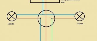
Wiring diagram for a chandelier with 2 lamps
There are 3 or 4 cables coming out of the ceiling. These are two phase cables from each key, one “zero” from the distribution box, grounding. Check with an indicator screwdriver. When checking, turn on the voltage, the keys are alternately in the “on” position. A wire without voltage is zero. It is designated. The remaining cables are phase cables.
In the lamp, all wiring is connected according to the accessory. That is, a modern lighting device contains phase leads for each horn, 1 zero, 1 ground.
In a lighting fixture with 2 arms, the phases are not connected. This means that you can make a connection so that either one light bulb or all of them will light up.
Grounding is connected immediately. After this you need to connect the zero. Chandelier-ceiling. The phases are removed from the device and connected to the corresponding keys.
Both lamps will light up simultaneously when 2 keys are pressed at once.
Connections should be insulated. Only after this turn on the power supply from the panel or meter.
Connecting light to three lamps with three wires
The three-arm chandelier contains 3 lamp sockets.
They have 2 contacts: N, L. The connection is carried out according to the same algorithm as a lamp with 2 horns, only one switch key will turn on 1 lamp, and the second - 2 light bulbs. If you press both keys at the same time, all the horns will light up.
The neutral cables from each horn are combined, the grounding is connected immediately.
The phases are divided into 2 groups.
Connection diagram for 4 bulbs
There are 2 phases coming out of the 2-key model, and zero, grounding, and phase cables are visible from the ceiling.
The connection can be made in 2 ways:
- 1+3=alternately turning on 1 lamp - 1 key and 3 lamps - the second key.
- 2+2 = 2 light bulbs turn on alternately. Moreover, you can make it so that 2 lamps located next to each other or crosswise are lit.
If you turn on both keys at the same time, 4 horns will light up.
The connection principle is as follows:
- The cables coming out of the lighting fixture are different colors or all the same. Then they make a call and mark the value (N, L).
- Grounding - it can be immediately connected to the ceiling.
- The blue ones are connected with one terminal - 1 blue wire comes out of the ceiling.
- The phases are divided into groups: the first - 3 wires, one separately or 2 groups of 2 pieces.
- Next, use terminals to connect the twists on the light fixture and the ceiling.
The twists are insulated so that they do not come into contact with each other.
When dividing into groups, so that the phase does not fall into the “zero” twist.
5-bar chandelier
A common “zero” comes out of the five-arm chandelier.
It must be marked (maybe with electrical tape). Sometimes there are several blue wires, they are combined with one twist. Attention. The distinction can be made using an indicator - whether there is voltage or not. If there is voltage - L, otherwise - N.
Phase wires are divided into 2 groups:
- The first twist will consist of 3 phases - one key will turn on 3 lamps.
- The second group - 2 phase twists - 2 horns, the other with a power key.
When the keys are turned on at once, 5 lamps light up.
After the groups have been created, the chandelier is connected to the wiring. After checking, if the wrong groups of lamps are lit (randomly), you can re-twist 2x3 (groups) by changing the phases.
Double connection diagram for 6 bulbs
Connecting a device with 6 lamps requires good wiring. Further, the two-key model for turning on the light provides operation in three modes: turning on the lamps in groups (2 modes) and turning on the lights in general. In this case, at least 3 wires should come out of the ceiling.
Let’s say group 1 – 2 lamps, 2nd – 4 lamps, third mode – all lamps are in working condition.
There are 12 wires coming out of the chandelier, 2 for each horn.
You need to select all the blue wires or those marked when ringing, connect them with one terminal (1 twist). The remaining cables are connected in groups (these are phase). 4 wires one terminal and 2 the other.
Before connecting the wires of the lamp to the ceiling, using an indicator screwdriver, determine the line L, zero N, as well as the assignment of L1, L2 to the keys. They do this with an indicator at constant current, with the keys turned on alternately. The found wires are marked with a marker or electrical tape. After this, you need to de-energize the network, connect the finished chandelier (connect zero to zero, and phase to phase). Grounding is connected immediately.
Scheme for double connection of a chandelier for 8 bulbs with 4 wires
4 wiring are visible from the ceiling: 2 phases (from the keys), 1 neutral, grounding.
Sometimes wires of the same color come out of the lamp. To determine phase and zero, it is necessary to ring with a multimeter and mark them in the same way as on the ceiling (so as not to confuse them).
“Zero” comes in one twist, because there is 1 neutral cable on the ceiling. Phase wiring is divided into 2 groups: 8 lamps are 3 lamps and 5 or 4x4, 2x7 and so on. Afterwards, the created groups of insulated wires or placed in terminals are connected accordingly to those marked on the ceiling.
An example of calculating the connection of lamps of different power
To understand the differences, it is enough to know Ohm's law and other simple electrical laws.
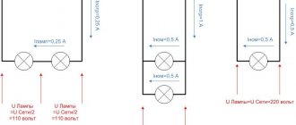
Let there be an incandescent light bulb with a voltage of 220 volts. At a frequency of 50 Hz, it represents a purely active resistance, so it is more convenient to understand initial questions with it. If the lamp has a power of 100 watts, then when connected to the network, a current I=P/U=100 watts/220 volts=0.5 A (approximately enough for reasoning). The full network voltage of 220 volts will drop across it. You can calculate the resistance of the thread: R=U/I=220 volts /0.5 amperes =400 Ohms (approximately).
If you connect a second similar light bulb in parallel with the first, then it is obvious that the entire mains voltage will be applied to each lamp. The current consumption Ipot will branch into two streams and current I=U/R=220 volts/400 Ohm=0.5 amperes . The current consumed will be equal to the sum of the two currents (as Kirchhoff's first law says) and will be 1 A. As a result, both lamps will be under full mains voltage, the rated current will flow through them, and the total luminous flux will be equal to twice the flux of one lamp.
Parallel and series connection of light sources of equal power.
If two identical lamps are connected in series, the mains voltage will be divided between them, and each will drop about 110 volts. The total resistance of the circuit will become equal to Rtot = 400 + 400 = 800 Ohm , and the current through each lamp (with a series connection it is the same for each element) will be / 800 Ohm = 0.25 A. The result is:
- only half of the mains voltage drops on each lamp;
- a current flows through each lamp, reduced by 2 times from the rated one.
To estimate the luminous flux of incandescent lamps for a given case, you can use the Joule-Lenz law. Incandescent lamps glow by heating the filament. Over a period of time t, the thread will release the amount of heat Q=I2*R*t=U*I*t . The current will be halved, the voltage on one lamp will also be halved. This means we can expect a decrease in luminous flux by 2*2=4 times . For two lamps, the flux will decrease by half relative to one lamp in nominal mode. That is, when connected in series, two light bulbs will shine approximately twice as dim as one.
The problem can be solved by using lamps with an operating voltage two times lower than the mains voltage . If you use two hundred-watt light sources with a voltage of 127 volts, then 220 volts will be divided in half, and each lamp will operate in nominal mode, the luminous flux will double compared to one lamp of the same power. But this does not get rid of the main drawback of such a circuit - when one lighting fixture fails, the circuit breaks, and the second lamp also stops shining.
All of the above applies to lamps with the same power. If the power of the lamps differs markedly, then the following effects occur in the circuits. Let one 220-volt lamp have a power of 70 watts, the other 140.
Then the rated current of the first is I1=P/U=70/220=0.3 amperes (rounded), the second is I2=140/220=0.7 amperes . The filament resistance of the less powerful lamp is R1=U/I=220/0.3=700 ohms , the second - R2=220/0.7=300 ohms .
A lamp with a higher power corresponds to a lower filament resistance.
Parallel and series connection of light sources of various powers.
With a parallel connection, the voltage on both devices will be equal, and each lamp will have its own current. The total current consumption is equal to the sum of two currents Ipotr = 0.3 + 0.7 = 1 ampere. Each lamp operates in nominal mode and consumes its own current.
In a series connection, the current will be limited by the resistance Rtotal = 300 + 700 = 1000 Ohms and will be equal to I = U/R = 220/1000 = 0.2 A. The voltage will be distributed proportionally to the thread resistance (power). On a 140 watt lamp it will be 1/3 of 220 volts - approximately 70 volts. On a low-power lamp - 2/3 of 220 volts. That is, about 140 volts. Both lamps will shine at a low level due to a decrease in voltage and current, but the mode for them will be light. It’s another matter if lamps at half the mains voltage are used. On a lamp of lower power, the voltage will be higher than permissible, and the greater the difference in power, the greater the difference. This lamp will soon fail. And this is another disadvantage of connecting lamps in series. Therefore, such a connection is used extremely rarely in practice. An exception is the series connection of fluorescent lamps. It is believed that with this scheme they work more steadily.
Series connection of fluorescent light sources. The starters here are also rated at 127 volts.
To summarize the differences between parallel and serial connection:
- when connected in parallel, the voltage on all consumers is the same, the current is distributed in proportion to the power of the lamps (if the power is the same, then the currents will be equal), the total current consumption is equal to the sum of the currents of all lamps;
- with a series connection, the current through all lamps will be the same, it is determined by the total resistance of the circuit (and will be less than the current of the lowest-power lamp), the voltage across consumers will be distributed in proportion to the power of the lamps (if it is the same, then the voltages will be equal).
Using these principles, you can analyze the operation of any circuit.
Types of lamps and connection diagrams
Before installing various types of lighting devices, it is advisable to familiarize yourself with the operating principle and their internal structure, as well as the features of the connection circuit to the power supply network. It is also important to know that each of the varieties is capable of working for a long time only if the operating rules are strictly observed.
Fluorescent lamps
Fluorescent lamps are often installed in office spaces.
In addition to traditional incandescent lamps, their fluorescent tubular analogues are often used to illuminate office and partially domestic spaces. They are most often installed at the following facilities:
- in workshops and on industrial production lines;
- in administrative buildings and in various boxes;
- in garages, shopping malls and similar public places.
They are used much less often at home - sometimes they are placed in the kitchen to illuminate the work area.
A feature of fluorescent illuminators is the impossibility of direct connection to a 220 Volt network, since high voltage is required to break down the gas column. To turn them on, a special electronic circuit is used, which includes starting elements such as a choke, a starter and a high-voltage capacitor (in some cases it is optional).
In recent years, throttle converters, which are uneconomical and very noisy during operation, have been replaced by the so-called “electronic ballast”. The order of its connection is usually indicated in the form of a diagram shown on the device body.
When using an electronic adapter, one gas-discharge lamp is connected, or two are installed at once, connected in series.
Halogen sources and LED lamps
When installing suspended ceilings, halogen lamps are traditionally installed.
Lighters of the first type are traditionally installed when installing suspended and suspended ceilings. They are also ideal when it is necessary to illuminate areas with high humidity, as they are available in several modifications. One of them is designed to operate on 12 Volts. To obtain them, a converter designed for the appropriate output voltage is installed in the ceiling area.
LED lamps are characterized by the presence of a built-in driver that allows you to receive the required supply voltage (12 or 24 Volts). Samples of LED illuminators, designed to operate from 220 Volts, turn on like incandescent lamps. But unlike conventional illuminators, it is not recommended to turn them on in a daisy chain.
It is important to select the correct type of lamps to determine the desired order of their connection. It is not allowed to connect energy-saving illuminators in a series chain; when installing fluorescent and halogen lamps, they are guided by their switching circuits. When the mains voltage is low, energy-saving lamps quickly fail, and fluorescent lights may not light up at all.
How to avoid mistakes
Electrical appliances must be connected to the network in compliance with electrical regulations. The connection features are not obvious and may be incomprehensible to people far from the topic.
It is important to consider:
- Each type of connection has features associated with Ohm's law. In a series connection, the current is equal in all parts of the circuit, while the voltage depends on the resistance. In a parallel connection, the voltage is the same, and the total current is the sum of the values of the individual sections.
- Any circuit should not be overloaded, as this can lead to unstable operation of the devices and damage to the conductors.
- In a parallel connection, the cross-section of the wires must correspond to the applied load, otherwise overheating of the conductors is inevitable, followed by melting of the winding and a short circuit.
- A phase is supplied to the switch, zero goes to the lighting fixture. Failure to comply with this rule may result in electric shock when replacing the lamp, since even when the device is turned off, the device is energized.
- The main wire from the lamp is connected to the common contact. If you connect it to a tap, only part of the circuit will work.
- Before installing the switch, it is better to mark the wires in advance. During installation, it will be easy to connect the same conductors together.
Failure to follow the recommendations may result in unstable operation of lighting equipment, rapid lamp burnout, and serious injury that could lead to life-threatening injuries.
One lamp - one switch
The simplest circuit consists of one lighting element and a single-key switch.
Theoretically, the connection does not differ from that described above - the neutral conductor goes directly from the distribution board to the consumer, but a breaker is inserted into the phase conductor. But almost everything looks a little more complicated.
To make this type of connection, you first need to decide on the location of the junction box.
It should be installed as close as possible to the installation location of the switch, while making it easy to access.
The number of wires required to create a branch directly depends on this. Its optimal location is under the ceiling above the switch.
And then everything is simple:
- We determine the location of the lighting element - the lamp (for example, in the center of the ceiling);
- We select the installation location of the breaker (conditionally - below the distribution box);
- We insert the wiring coming from the distribution board into the distribution box;
- We lay the wiring along the ceiling (along the shortest possible path) from the lamp socket and also put it into the box;
- All that remains is to lay the wire from the switch to the junction box.
For simplicity, we will designate the wire going from the switchboard to the box as “input”, and from the box to the consumer as “output”.
For a circuit with a single-key switch and one lamp, two-core wires are used.
After laying all the wiring (in an open or closed way), all that remains is to connect everything correctly and for this it is important to determine which core is phase and which is neutral.
You can find out this using an indicator screwdriver, making an appropriate check at the terminals from the distribution board before turning off the power supply.
Circuit diagram of a switch and power socket through one distribution box.
Often there is a need to connect additional power sources in one room of the premises. In this case, you can make the connection through the distribution box through which the lamp is already connected. The picture shows a diagram of a switch and socket.
To do this, you need to install the socket housing on the wall, not far from the box. Strip the insulation from the ends of the wires coming from the socket and connect them by twisting to the wiring located in the box. The phase wire from the outlet is connected to the power base (2 red wires), and the zero to the zero line (2 blue wires). The wires to the power outlet are connected, just like to a switch, through threaded contacts. The socket body is turned with one screw - in the middle.
Next, the connections are tinned with solder, as in the case of a switch, and insulated with PVC tape. Checking the circuit of the switch and socket can be done using a special device, or simply by plugging in the power supply into the socket.
vote
Article rating
Connection from an outlet
But there are times when it is necessary to connect an additional lamp with a separate switch. Then it is possible to install wiring from an existing outlet. It makes no sense to discuss the choice of method of management (external or internal) now; this is not relevant to this topic. It is more logical to consider connection options. When installing a single-key switch, no difficulties arise; you only need a two-wire wire and the switching device itself.
If the voltage breaker is installed above the socket, then the neutral and phase wires are removed from it. The phase is interrupted inside the switch, while the zero remains intact. The rest of the lighting equipment connected to the circuit is powered according to the above circuits.
With a similar installation of a two-key switch, three wire strands are required (output - zero, phase, phase), and if the breaker has three keys, then 4 wires are needed (zero and 3 phases).